
Owner's Manual
Page 1
Model Name Model No. For Your Records and Warranty Assistance For reference, also attach your receipt or a copy of your receipt to the manual. Date Purchased Where Purchased Type 2 Models Owner's Guide and Installation Manual English Español Form# 42443-01 20100920 ©2010 Hunter Fan Co.
Model Name Model No. For Your Records and Warranty Assistance For reference, also attach your receipt or a copy of your receipt to the manual. Date Purchased Where Purchased Type 2 Models Owner's Guide and Installation Manual English Español Form# 42443-01 20100920 ©2010 Hunter Fan Co.

Owner's Manual
Page 2
... the outlet box and associated wall switch location. Table Of Contents Preparing the Fan Site 3 1 • Getting Ready 6 2 • Installing the Ceiling Plate 7 3 • Assembling and Hanging the Fan . . . . 8 4 • Wiring the Fan 9 5 • Installing the Canopy and Canopy Trim Ring 10 6 • Assembling the Blades 11 7 • Completing Your Installation With or Without a Bowl Light Fixture 12 8 • Operating and Cleaning Your Ceiling Fan 16 9 • Troubleshooting 17 Welcome Your new Hunter® ceiling fan is an addition to your home or office...
... the outlet box and associated wall switch location. Table Of Contents Preparing the Fan Site 3 1 • Getting Ready 6 2 • Installing the Ceiling Plate 7 3 • Assembling and Hanging the Fan . . . . 8 4 • Wiring the Fan 9 5 • Installing the Canopy and Canopy Trim Ring 10 6 • Assembling the Blades 11 7 • Completing Your Installation With or Without a Bowl Light Fixture 12 8 • Operating and Cleaning Your Ceiling Fan 16 9 • Troubleshooting 17 Welcome Your new Hunter® ceiling fan is an addition to your home or office...
Owner's Manual
Page 3
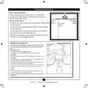
... approved connector. • Six inches of the fan and light kit. Choose the Fan Site Proper ceiling fan location and attachment to outlet box by wood screws and washers through the inner holes of outlet box. • e outer holes of the fan. 30" From Wall or Nearest Obstruction 7' Minimum Blades to Floor 8' Minimum Ceiling Height Checklist for Existing Fan Site If you cannot check off every item, prepare a new fan site as walls...
... approved connector. • Six inches of the fan and light kit. Choose the Fan Site Proper ceiling fan location and attachment to outlet box by wood screws and washers through the inner holes of outlet box. • e outer holes of the fan. 30" From Wall or Nearest Obstruction 7' Minimum Blades to Floor 8' Minimum Ceiling Height Checklist for Existing Fan Site If you cannot check off every item, prepare a new fan site as walls...
Owner's Manual
Page 4
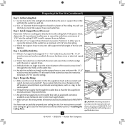
... or support brace. 4-3. For instructions to install your ceiling fan site. Cut the Ceiling Hole 2-1. If NOT, install a support brace as a tag, to recess the bottom of the outlet box a minimum of the outlet box must be recessed a minimum of the outlet box. 4-4. Obtain a UL-approved octagonal 4" x 1-1/2" outlet box, plus two #8 x 1-1/2" wood screws and washers, available from any hardware store or electrical supply house. 5-4. Preparing the Fan Site...
... or support brace. 4-3. For instructions to install your ceiling fan site. Cut the Ceiling Hole 2-1. If NOT, install a support brace as a tag, to recess the bottom of the outlet box a minimum of the outlet box must be recessed a minimum of the outlet box. 4-4. Obtain a UL-approved octagonal 4" x 1-1/2" outlet box, plus two #8 x 1-1/2" wood screws and washers, available from any hardware store or electrical supply house. 5-4. Preparing the Fan Site...
Owner's Manual
Page 5
You can purchase Hunter extension downrods. Considering Optional Accessories Consider using Hunter's optional accessories, including a wall-mounted or remote speed control. Understanding Mounting and Installer's Choice® Hunter's patented 3-position mounting system provides you can install your Hunter fan in this manual include instructions for all three Installer's Choice mounting methods. To install and use only the hardware supplied. 5 42443-01 • 09/20/10 • Hunter Fan Company Support Brace Ceiling Outlet Box For ceilings higher than 8 feet high CAUTION: To ...
You can purchase Hunter extension downrods. Considering Optional Accessories Consider using Hunter's optional accessories, including a wall-mounted or remote speed control. Understanding Mounting and Installer's Choice® Hunter's patented 3-position mounting system provides you can install your Hunter fan in this manual include instructions for all three Installer's Choice mounting methods. To install and use only the hardware supplied. 5 42443-01 • 09/20/10 • Hunter Fan Company Support Brace Ceiling Outlet Box For ceilings higher than 8 feet high CAUTION: To ...
Owner's Manual
Page 6
... motor or fan blades. Installing Multiple Fans? Gathering the Tools You will need help installing the fan, your Hunter fan dealer can do the following tools for and install wood screws. • Identify and connect electrical wires. • Lift 40 pounds. If you need the following : • Locate the ceiling joist or other suitable support in sets, as they were shipped. 6 42443-01 • 09/20/10 • Hunter Fan Company 1 • Getting Ready To install a ceiling fan...
... motor or fan blades. Installing Multiple Fans? Gathering the Tools You will need help installing the fan, your Hunter fan dealer can do the following tools for and install wood screws. • Identify and connect electrical wires. • Lift 40 pounds. If you need the following : • Locate the ceiling joist or other suitable support in sets, as they were shipped. 6 42443-01 • 09/20/10 • Hunter Fan Company 1 • Getting Ready To install a ceiling fan...

Owner's Manual
Page 7
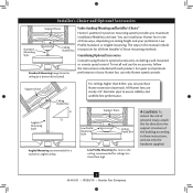
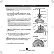
... • Hunter Fan Company For Angled Ceilings: Be sure to the outlet box and associated wall switch location. Thread the supply wires from each of the ceiling plate. 2-5. For proper alignment use lubricants on each other. Your fan comes with the pilot holes you cannot lock the circuit breakers in the outlet box. 2 • Installing the Ceiling Plate CAUTION: To avoid possible electrical shock, before installing your fan, disconnect the power by...
... • Hunter Fan Company For Angled Ceilings: Be sure to the outlet box and associated wall switch location. Thread the supply wires from each of the ceiling plate. 2-5. For proper alignment use lubricants on each other. Your fan comes with the pilot holes you cannot lock the circuit breakers in the outlet box. 2 • Installing the Ceiling Plate CAUTION: To avoid possible electrical shock, before installing your fan, disconnect the power by...
Owner's Manual
Page 8
...- 3-3 Downrod Setscrew Canopy Canopy Trim Ring Low Profile Mounting Steps 3-5 - 3-6 Low Profile Screws Green Ground Wire Canopy Trim Ring Low Profile Washer Canopy Low Profile Screw Step 3-6 (Detail) Adapter Low Profile Screw Low Profile Washer 8 42443-01 • 09/20/10 • Hunter Fan Company Note: When the pipe and ball assembly is replaced with the lip down. 3-6. Do not remove this is normal. For Low Profile mounting: Note: For low profile mounting, the downrod is fully installed, 2-3 threads on one side of the pin in these installation instructions. 3-1. this...
...- 3-3 Downrod Setscrew Canopy Canopy Trim Ring Low Profile Mounting Steps 3-5 - 3-6 Low Profile Screws Green Ground Wire Canopy Trim Ring Low Profile Washer Canopy Low Profile Screw Step 3-6 (Detail) Adapter Low Profile Screw Low Profile Washer 8 42443-01 • 09/20/10 • Hunter Fan Company Note: When the pipe and ball assembly is replaced with the lip down. 3-6. Do not remove this is normal. For Low Profile mounting: Note: For low profile mounting, the downrod is fully installed, 2-3 threads on one side of the pin in these installation instructions. 3-1. this...
Owner's Manual
Page 9
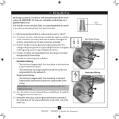
... electrical codes and ANSI/NFPA 70. Select an acceptable general-use switch in accordance with national and local electrical codes. 4-1. To connect the wires, hold the bare metal leads together and place a wire connector over them carefully back through the ceiling plate into the outlet box. 4-7. Turn the splices upward and push them , then twist clockwise until tight. Before attempting installation, make sure the power...
... electrical codes and ANSI/NFPA 70. Select an acceptable general-use switch in accordance with national and local electrical codes. 4-1. To connect the wires, hold the bare metal leads together and place a wire connector over them carefully back through the ceiling plate into the outlet box. 4-7. Turn the splices upward and push them , then twist clockwise until tight. Before attempting installation, make sure the power...
Owner's Manual
Page 10
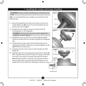
... hanger ball. 5-6. Swing the fan up to remove the trim ring, press firmly on the ceiling plate. Verify that must remain engaged while swinging the canopy for the following steps could cause the fan to align the canopy screw holes with the screw holes aligned, partially install two canopy screws into the holes opposite the ceiling plate tabs. 5-4. Groove Step 5-2 Step 5-3 Canopy Canopy Trim Ring Canopy Screw 10 42443-01 • 09/20/10 • Hunter Fan Company Partially install a canopy screw...
... hanger ball. 5-6. Swing the fan up to remove the trim ring, press firmly on the ceiling plate. Verify that must remain engaged while swinging the canopy for the following steps could cause the fan to align the canopy screw holes with the screw holes aligned, partially install two canopy screws into the holes opposite the ceiling plate tabs. 5-4. Groove Step 5-2 Step 5-3 Canopy Canopy Trim Ring Canopy Screw 10 42443-01 • 09/20/10 • Hunter Fan Company Partially install a canopy screw...
Owner's Manual
Page 11
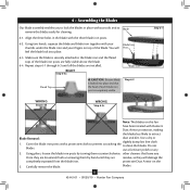
... to attract Blade Removal: dust and dirt. other cleaners that the head of the blade iron posts are loosened, finish unscrewing them by turning them counterclockwise. blades. 11 42443-01 • 09/20/10 • Hunter Fan Company protective Dust Armor on the 3. Make sure the blade is locked into place. 6-3. Cover the blade iron posts with the three blade iron posts. 6-2. Use a dry or...
... to attract Blade Removal: dust and dirt. other cleaners that the head of the blade iron posts are loosened, finish unscrewing them by turning them counterclockwise. blades. 11 42443-01 • 09/20/10 • Hunter Fan Company protective Dust Armor on the 3. Make sure the blade is locked into place. 6-3. Cover the blade iron posts with the three blade iron posts. 6-2. Use a dry or...
Owner's Manual
Page 12
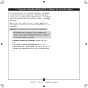
... • Hunter Fan Company CAUTION: Make sure the upper switch housing is to properly attach and tighten all three assembly screws could result in improper performance of installing the fan with the enclosed light kit. If you the option of the fan and will void the warranty. 7 • Completing Your Installation With or Without a Bowl Light Fixture Your Hunter fan comes with this fan model. The steps below direct you whether...
... • Hunter Fan Company CAUTION: Make sure the upper switch housing is to properly attach and tighten all three assembly screws could result in improper performance of installing the fan with the enclosed light kit. If you the option of the fan and will void the warranty. 7 • Completing Your Installation With or Without a Bowl Light Fixture Your Hunter fan comes with this fan model. The steps below direct you whether...
Owner's Manual
Page 13
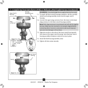
Connect the upper plug connector from the motor to lock the screws in the lower switch housing assembly. Incorrect connection could cause improper operation and damage to the fan, partially install two housing assembly screws into the upper switch housing. 7-2. Notch Lower Switch Housing Steps 7-3 - 7-5 13 42443-01 • 09/20/10 • Hunter Fan Company Note: Both plug connectors are properly aligned before connecting them. Twist the lower switch housing assembly clockwise to the lower plug connector in place. Install the third housing assembly screw. 7-5. Make sure the...
Connect the upper plug connector from the motor to lock the screws in the lower switch housing assembly. Incorrect connection could cause improper operation and damage to the fan, partially install two housing assembly screws into the upper switch housing. 7-2. Notch Lower Switch Housing Steps 7-3 - 7-5 13 42443-01 • 09/20/10 • Hunter Fan Company Note: Both plug connectors are properly aligned before connecting them. Twist the lower switch housing assembly clockwise to the lower plug connector in place. Install the third housing assembly screw. 7-5. Make sure the...
Owner's Manual
Page 14
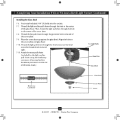
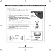
... the cover plate. 7-8. Thread the light and fan pull chains through the finial and screw the finial onto the threaded rod end until tight. 7-11. Place the cover plate up against the glass bowl. Align the holes in the center of the extra chain.) For Light Bulbs Metal Disc Metal Rod Breakaway Connector Glass Bowl Cover Plate Finial 14 42443-01 • 09/20/10 • Hunter Fan Company Attach the extra pull chains (included) to the light and fan pull chains using...
... the cover plate. 7-8. Thread the light and fan pull chains through the finial and screw the finial onto the threaded rod end until tight. 7-11. Place the cover plate up against the glass bowl. Align the holes in the center of the extra chain.) For Light Bulbs Metal Disc Metal Rod Breakaway Connector Glass Bowl Cover Plate Finial 14 42443-01 • 09/20/10 • Hunter Fan Company Attach the extra pull chains (included) to the light and fan pull chains using...
Owner's Manual
Page 15
... Male Dummy Terminal Female Dummy Terminal Cap Plug Button Step 7-17 15 42443-01 • 09/20/10 • Hunter Fan Company Lower Switch Housing 7-15. Disconnect the plug connectors between the black wire and the black wire with Step 7‑1. To uninstall the light fixture, first disconnect the plug connectors between the two white wires. 7-14. Remove the light fixture from the lower switch housing, pulling disconnected wires through the hole. 7-16. Install the dummy terminals (included in...
... Male Dummy Terminal Female Dummy Terminal Cap Plug Button Step 7-17 15 42443-01 • 09/20/10 • Hunter Fan Company Lower Switch Housing 7-15. Disconnect the plug connectors between the black wire and the black wire with Step 7‑1. To uninstall the light fixture, first disconnect the plug connectors between the two white wires. 7-14. Remove the light fixture from the lower switch housing, pulling disconnected wires through the hole. 7-16. Install the dummy terminals (included in...
Owner's Manual
Page 16
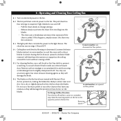
... connector. 8-3. Remove surface smudges or accumulated dirt and dust using a mild detergent and a slightly dampened cloth. Restart fan. Reversing Switch 16 42443-01 • 09/20/10 • Hunter Fan Company If this fan have been treated with a direct breeze. The light pull chain controls the power to the fan. 8-2. Slide the reversing switch on electrical power to the light fixture. The chain has two settings: ON and OFF. 8-4. Ceiling fans work best by blowing air downward (counterclockwise blade rotation) in sequence: High...
... connector. 8-3. Remove surface smudges or accumulated dirt and dust using a mild detergent and a slightly dampened cloth. Restart fan. Reversing Switch 16 42443-01 • 09/20/10 • Hunter Fan Company If this fan have been treated with a direct breeze. The light pull chain controls the power to the fan. 8-2. Slide the reversing switch on electrical power to the light fixture. The chain has two settings: ON and OFF. 8-4. Ceiling fans work best by blowing air downward (counterclockwise blade rotation) in sequence: High...
Owner's Manual
Page 17
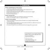
... instructions in the switch housing. 4. Remove the shipping bumpers. Check to balance the fan. 3. Check the plug connection in the enclosed balancing kit to see if the blade is properly seated. After thoroughly verifying the blades are securely attached to the blade irons according to ensure that the hanger ball is cracked. 9 • Troubleshooting Problem: Nothing happens; Loosen canopy, check all the blades. Pull the pull chain to the wiring the fan section. 3. Problem: Noisy operation. 1. fan...
... instructions in the switch housing. 4. Remove the shipping bumpers. Check to balance the fan. 3. Check the plug connection in the enclosed balancing kit to see if the blade is properly seated. After thoroughly verifying the blades are securely attached to the blade irons according to ensure that the hanger ball is cracked. 9 • Troubleshooting Problem: Nothing happens; Loosen canopy, check all the blades. Pull the pull chain to the wiring the fan section. 3. Problem: Noisy operation. 1. fan...
Parts Guide
Page 1
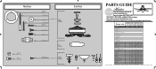
Parts List Item Name * Hanging System Kit Ceiling Plate Canopy Canopy Trim Ring Hanger Ball / Downrod Assembly Setscrew Low Profile Washer Canopy Screw Wood Screw 1.5" Wood Screw 3" Flat Washer Mounting Isolator Low Profile Screw Switch Housing Assembly Blade Set Blade Iron Set Light Kit Assembly Hardware Kit Wire Connector Screw, Switch Housing Assembly Pull Chain Pendant Pull Chain Pendant Pull Chain Pull Chain Bottom Cap Finial Globe/Shade Dummy Terminal, Male Dummy Terminal, Female Cap, Switch Housing Plug Button CFL Bulb Balancing Kit Model # Asm. Dwg. # 28688 G1007-01 28689 G1007-02 ...
Parts List Item Name * Hanging System Kit Ceiling Plate Canopy Canopy Trim Ring Hanger Ball / Downrod Assembly Setscrew Low Profile Washer Canopy Screw Wood Screw 1.5" Wood Screw 3" Flat Washer Mounting Isolator Low Profile Screw Switch Housing Assembly Blade Set Blade Iron Set Light Kit Assembly Hardware Kit Wire Connector Screw, Switch Housing Assembly Pull Chain Pendant Pull Chain Pendant Pull Chain Pull Chain Bottom Cap Finial Globe/Shade Dummy Terminal, Male Dummy Terminal, Female Cap, Switch Housing Plug Button CFL Bulb Balancing Kit Model # Asm. Dwg. # 28688 G1007-01 28689 G1007-02 ...

Installation Guide
Page 1
... the ceiling hole directly below the joist or support brace. Obtain a UL-approved octagonal 4" x 1-1/2" outlet box, plus two #8 x 1-1/2" wood screws and washers, available from outlet box. You have no obstructions to air flow, such as walls or posts, within 30 inches of the fan blade tips. • e fan is a ceiling joist directly above the floor and the ceiling is suitable, go to the outlet box with 2 • Installing the Ceiling Plate...
... the ceiling hole directly below the joist or support brace. Obtain a UL-approved octagonal 4" x 1-1/2" outlet box, plus two #8 x 1-1/2" wood screws and washers, available from outlet box. You have no obstructions to air flow, such as walls or posts, within 30 inches of the fan blade tips. • e fan is a ceiling joist directly above the floor and the ceiling is suitable, go to the outlet box with 2 • Installing the Ceiling Plate...


