

Installation Guide
Page 1
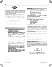
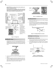
... 30 inches of 1/16" into the ceiling. 3-2. Locate the site for your fan manual and begin with 2 • Installing the Ceiling Plate. Steps 2 - 3 Step 3 Install a Support Brace, If Necessary Determine if there is a ceiling joist directly above the floor and the ceiling is recessed a minimum of the fan blade tips. • e fan is acceptable and safe for the ceiling hole directly below the joist or support brace. For instructions to install your ceiling fan...
... 30 inches of 1/16" into the ceiling. 3-2. Locate the site for your fan manual and begin with 2 • Installing the Ceiling Plate. Steps 2 - 3 Step 3 Install a Support Brace, If Necessary Determine if there is a ceiling joist directly above the floor and the ceiling is recessed a minimum of the fan blade tips. • e fan is acceptable and safe for the ceiling hole directly below the joist or support brace. For instructions to install your ceiling fan...
Owner's Manual
Page 2
... remote speed control. For quiet and optimum performance of personal injury, do the following: • Locate the ceiling joist or other suitable support in the off the circuit breakers to your home or office that will need help installing the fan, your Hunter fan dealer can purchase Hunter extension downrods. If one fan, keep the fan blades in sets, as a tag, to supply you should use the accessories, follow the instructions included with the best ceiling fan...
... remote speed control. For quiet and optimum performance of personal injury, do the following: • Locate the ceiling joist or other suitable support in the off the circuit breakers to your home or office that will need help installing the fan, your Hunter fan dealer can purchase Hunter extension downrods. If one fan, keep the fan blades in sets, as a tag, to supply you should use the accessories, follow the instructions included with the best ceiling fan...
Owner's Manual
Page 3
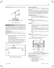
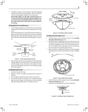
... fan blades are preparing a new fan site, go to joist or support brace by approved connector. • Six inches of fan and light kit. outlet box • UL-approved octagonal 4" x 1-1/2" outlet box listed as specified by the support brace manufacturer). • Outlet box secured to the installing the ceiling plate section and begin installing your new fan. Minimum mounting distances 41877-01 06/14/2007 Washer Wood Screw Ceiling Outlet Box Figure 4 - See Figure 4 for your new Hunter fan. ceiling hole...
... fan blades are preparing a new fan site, go to joist or support brace by approved connector. • Six inches of fan and light kit. outlet box • UL-approved octagonal 4" x 1-1/2" outlet box listed as specified by the support brace manufacturer). • Outlet box secured to the installing the ceiling plate section and begin installing your new fan. Minimum mounting distances 41877-01 06/14/2007 Washer Wood Screw Ceiling Outlet Box Figure 4 - See Figure 4 for your new Hunter fan. ceiling hole...
Owner's Manual
Page 4
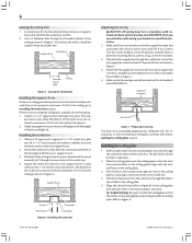
... holes should use the hole to install the support brace and outlet box. Thread the lead wires from any hardware store or electrical supply house. Align the slotted holes (refer to be recessed a minimum of the ceiling plate. 5. Support Brace Washer Outlet Box Wood Screw 1/16" Recess Figure 6 - Refer to the fan supply line leads and associated wall switch location are pointing towards the ceiling peak. installing the ceiling plate 1. Refer to match the holes...
... holes should use the hole to install the support brace and outlet box. Thread the lead wires from any hardware store or electrical supply house. Align the slotted holes (refer to be recessed a minimum of the ceiling plate. 5. Support Brace Washer Outlet Box Wood Screw 1/16" Recess Figure 6 - Refer to the fan supply line leads and associated wall switch location are pointing towards the ceiling peak. installing the ceiling plate 1. Refer to match the holes...
Owner's Manual
Page 5
... of the motor housing. 4. Place a flat washer on the ceiling plate as described in Figure 11. Use the note and arrow engraved in the ceiling plate to assist in these installation instructions. Hanging the fan wiring the fan 1. To connect the wires, twist the bare metal leads together. To keep the adapter ring assembled, twist the adapter cover around the downrod until it is no separate wall switch power wire for the light fixture. Tighten downrod set screw as directed in determining...
... of the motor housing. 4. Place a flat washer on the ceiling plate as described in Figure 11. Use the note and arrow engraved in the ceiling plate to assist in these installation instructions. Hanging the fan wiring the fan 1. To connect the wires, twist the bare metal leads together. To keep the adapter ring assembled, twist the adapter cover around the downrod until it is no separate wall switch power wire for the light fixture. Tighten downrod set screw as directed in determining...
Owner's Manual
Page 6
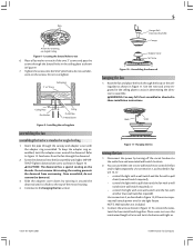
... canopy and the ceil- Tab Hole and Tab Canopy Screw Figure 14 - Remove the blade mounting screws and rubber shipping bumpers from the fan to Figure 13. Refer to the wall switch for separate control of the switch housing gasket and the upper switch housing. Figure 13 - ing plate are assembled, securely tighten all three screws are aligned, and loosely assemble the canopy screws one blade mounting screw through the center opening of the light fixture, or 2. The arrows on the hanger...
... canopy and the ceil- Tab Hole and Tab Canopy Screw Figure 14 - Remove the blade mounting screws and rubber shipping bumpers from the fan to Figure 13. Refer to the wall switch for separate control of the switch housing gasket and the upper switch housing. Figure 13 - ing plate are assembled, securely tighten all three screws are aligned, and loosely assemble the canopy screws one blade mounting screw through the center opening of the light fixture, or 2. The arrows on the hanger...
Owner's Manual
Page 7
...the cap and plug button 41877-01 06/14/2007 © 2007 Hunter Fan Company Tighten the screws securely. NOTE: Both plug connectors are properly aligned before connecting them together. Install the upper switch housing as shown in the attaching the upper switch housing section. 2. Incorrect connection could result in Globe Assembly Fitter Fitter Cover Globe Assembly Figure 18 - Installing the globe assembly installing without the light fixture 1. attaching the lower switch housing 1. Lower Plug Connector Housing Assembly Screw Upper Switch Housing Upper Plug Connector...
...the cap and plug button 41877-01 06/14/2007 © 2007 Hunter Fan Company Tighten the screws securely. NOTE: Both plug connectors are properly aligned before connecting them together. Install the upper switch housing as shown in the attaching the upper switch housing section. 2. Incorrect connection could result in Globe Assembly Fitter Fitter Cover Globe Assembly Figure 18 - Installing the globe assembly installing without the light fixture 1. attaching the lower switch housing 1. Lower Plug Connector Housing Assembly Screw Upper Switch Housing Upper Plug Connector...
Owner's Manual
Page 8
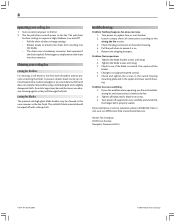
... used , but never use the enclosed balancing kit and instructions to balance the fan. 2. Tighten the blade screws until snug. 2. Problem: Excessive wobbling. 1. If your ceiling fan 1. Tighten all connections according to see if the blade is on. 5. Turn on , replace fuse, or reset breaker. 2. The fan pull chain controls power to an approved speed control. 5. A vacuum cleaner brush nozzle can easily be cleaned in sequence: High, Medium, Low and Off. • Pull the chain slowly to change settings...
... used , but never use the enclosed balancing kit and instructions to balance the fan. 2. Tighten the blade screws until snug. 2. Problem: Excessive wobbling. 1. If your ceiling fan 1. Tighten all connections according to see if the blade is on. 5. Turn on , replace fuse, or reset breaker. 2. The fan pull chain controls power to an approved speed control. 5. A vacuum cleaner brush nozzle can easily be cleaned in sequence: High, Medium, Low and Off. • Pull the chain slowly to change settings...
Parts Guide
Page 1
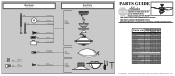
... INSTALLATION MANUAL FOR FULL ASSEMBLY INSTRUCTIONS. Parts List Item Name Ceiling Plate Canopy Ceiling Plate Gasket Wood Screw Wood Screw Flat Washer Setscrew Canopy Screw Adapter Cover Adapter Gasket Light Kit Assembly Blade Screw, Blade Iron Armature Hardware Kit Screw, Machine, 6-32 Wire Connector Balancing Kit Globe/Shade Dummy Terminal, Male Dummy Terminal, Female Cap, Switch Housing Plug Button CFL Bulb Model # 25522 25521 Asm. Hardware (Drawn to Scale) x 2 x 2 3" Wood Screw x 4 Flat Washer 1.5" Wood Screw x 4 Canopy Screw x 1 Setscrew x 4 Mounting Isolator Balancing...
... INSTALLATION MANUAL FOR FULL ASSEMBLY INSTRUCTIONS. Parts List Item Name Ceiling Plate Canopy Ceiling Plate Gasket Wood Screw Wood Screw Flat Washer Setscrew Canopy Screw Adapter Cover Adapter Gasket Light Kit Assembly Blade Screw, Blade Iron Armature Hardware Kit Screw, Machine, 6-32 Wire Connector Balancing Kit Globe/Shade Dummy Terminal, Male Dummy Terminal, Female Cap, Switch Housing Plug Button CFL Bulb Model # 25522 25521 Asm. Hardware (Drawn to Scale) x 2 x 2 3" Wood Screw x 4 Flat Washer 1.5" Wood Screw x 4 Canopy Screw x 1 Setscrew x 4 Mounting Isolator Balancing...


