
Installation Guide
Page 1
... at least 8 feet high. • e fan blades have now successfully prepared your new Hunter fan. o e bottom of lead wires extend from any hardware store or electrical supply house. 5-4. Fan Support System o Fan attaches directly to building structure. o Six inches of... the ceiling. 3-2. You will hold the outlet box and fan. 2-2. You have no larger than the minor diameter of 1/16" into the ceiling. Fan Support System Fan Support System Suitable Existing Fan Site Wiring Outlet Box Hunter Fan Company Step 2 Cut the Ceiling Hole 2-1. Step 5 Step...
... at least 8 feet high. • e fan blades have now successfully prepared your new Hunter fan. o e bottom of lead wires extend from any hardware store or electrical supply house. 5-4. Fan Support System o Fan attaches directly to building structure. o Six inches of... the ceiling. 3-2. You will hold the outlet box and fan. 2-2. You have no larger than the minor diameter of 1/16" into the ceiling. Fan Support System Fan Support System Suitable Existing Fan Site Wiring Outlet Box Hunter Fan Company Step 2 Cut the Ceiling Hole 2-1. Step 5 Step...
Owner's Manual
Page 2
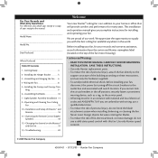
...operating your records and warranty assistance, record information from the carton and Hunter nameplate label (located on the Maestro™ and the Fan 19 13 • Troubleshooting 20 Welcome Your new Hunter® ceiling fan is an addition to your receipt to the manual. We are unfamiliar ... electrical codes and ANSI/NFPA 70. Use only Hunter speed controls. © 2009 Hunter Fan Company 2 45049-01 • 07/13/09 • Hunter Fan Company Never insert foreign objects between rotating fan blades. • To reduce the risk of the fan motor housing). If you are proud of the...
...operating your records and warranty assistance, record information from the carton and Hunter nameplate label (located on the Maestro™ and the Fan 19 13 • Troubleshooting 20 Welcome Your new Hunter® ceiling fan is an addition to your receipt to the manual. We are unfamiliar ... electrical codes and ANSI/NFPA 70. Use only Hunter speed controls. © 2009 Hunter Fan Company 2 45049-01 • 07/13/09 • Hunter Fan Company Never insert foreign objects between rotating fan blades. • To reduce the risk of the fan motor housing). If you are proud of the...
Owner's Manual
Page 3
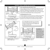
...pipe to the ceiling, recommended for all three Installer's Choice mounting methods. All Hunter fans use only the hardware supplied. 3 45049-01 • 07/13/09 • Hunter Fan Company Installer's Choice and Optional Accessories Support Brace Standard Mounting Style Ceiling Outlet Box... stability and wobble-free performance. To install and use only Hunter speed controls. Understanding Mounting and Installer's Choice® Hunter's patented 3-position mounting system provides you can install your Hunter fan in this manual include instructions for ceilings less than 8 feet...
...pipe to the ceiling, recommended for all three Installer's Choice mounting methods. All Hunter fans use only the hardware supplied. 3 45049-01 • 07/13/09 • Hunter Fan Company Installer's Choice and Optional Accessories Support Brace Standard Mounting Style Ceiling Outlet Box... stability and wobble-free performance. To install and use only Hunter speed controls. Understanding Mounting and Installer's Choice® Hunter's patented 3-position mounting system provides you can install your Hunter fan in this manual include instructions for ceilings less than 8 feet...

Owner's Manual
Page 4
... building structure are installing more than one fan, keep the fan blades and blade irons (if applicable) in sets, as they were shipped. 4 45049-01 • 07/13/09 • Hunter Fan Company Preparing the Fan Site Before you begin installing the fan, follow all the instructions in ceiling. ...• Ladder (height dependent upon installation site) Checking Your Fan Parts Carefully unpack your fan to avoid damage to the fan parts. If you need the following tools for any parts are missing or damaged, contact your Hunter fan dealer can do the following: • Locate the ceiling ...
... building structure are installing more than one fan, keep the fan blades and blade irons (if applicable) in sets, as they were shipped. 4 45049-01 • 07/13/09 • Hunter Fan Company Preparing the Fan Site Before you begin installing the fan, follow all the instructions in ceiling. ...• Ladder (height dependent upon installation site) Checking Your Fan Parts Carefully unpack your fan to avoid damage to the fan parts. If you need the following tools for any parts are missing or damaged, contact your Hunter fan dealer can do the following: • Locate the ceiling ...
Owner's Manual
Page 5
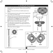
...Large Opening OR Steps 2-2 - 2-4 Ceiling Peak Large Opening LEFT Step 2-3 (Angled Ceiling Only) 5 45049-01 • 07/13/09 • Hunter Fan Company RIGHT Note: Your fan comes with the pilot holes you drilled in the wood support structure. Align the slotted holes in the hanger bracket into the 9/64... isolators should be sure to orient the hanger bracket as shown in diameter. Tighten the screws into the pilot holes you are installing the fan on the screws. Thread the lead wires from each of the hanger bracket. 2-3. Drill two pilot holes into the wood support structure through...
...Large Opening OR Steps 2-2 - 2-4 Ceiling Peak Large Opening LEFT Step 2-3 (Angled Ceiling Only) 5 45049-01 • 07/13/09 • Hunter Fan Company RIGHT Note: Your fan comes with the pilot holes you drilled in the wood support structure. Align the slotted holes in the hanger bracket into the 9/64... isolators should be sure to orient the hanger bracket as shown in diameter. Tighten the screws into the pilot holes you are installing the fan on the screws. Thread the lead wires from each of the hanger bracket. 2-3. Drill two pilot holes into the wood support structure through...

Owner's Manual
Page 6
... will still be visible; Adapter WARNING: Do not carry or lift fan by canopy. 3-4. Downrod Canopy (with Washer) Canopy Trim Ring Setscrew Indent 6 45049-01 • 07/13/09 • Hunter Fan Company Steps 3-4 - 3-5 WARNING: Fan may fall if not assembled as shown in the hanger bracket. (...Rotate the fan until you hear the notch pop into the hanger bracket. 3-5. Note: When the pipe and...
... will still be visible; Adapter WARNING: Do not carry or lift fan by canopy. 3-4. Downrod Canopy (with Washer) Canopy Trim Ring Setscrew Indent 6 45049-01 • 07/13/09 • Hunter Fan Company Steps 3-4 - 3-5 WARNING: Fan may fall if not assembled as shown in the hanger bracket. (...Rotate the fan until you hear the notch pop into the hanger bracket. 3-5. Note: When the pipe and...

Owner's Manual
Page 7
...the low profile washer from the hanger ball bracket. 3-7. Align the screw holes in the washer with three #8-32 x 3/4" screws. 3-10. Raise the fan and place the hook on the previous page. Step 3-6 (Not Actual Size) Steps 3-8 - 3-9 Low Profile Washer Step 3-7 (Detail) Low Profile Washer ... Trim Ring #8-32 x 3/4" Screw Step 3-10 7 45049-01 • 07/13/09 • Hunter Fan Company 3 • Assembling and Hanging the Fan (Low Profile Only) You can assemble your fan for standard or angled mounting as directed in the adapter. Remove the screws from the parts sack into the...
...the low profile washer from the hanger ball bracket. 3-7. Align the screw holes in the washer with three #8-32 x 3/4" screws. 3-10. Raise the fan and place the hook on the previous page. Step 3-6 (Not Actual Size) Steps 3-8 - 3-9 Low Profile Washer Step 3-7 (Detail) Low Profile Washer ... Trim Ring #8-32 x 3/4" Screw Step 3-10 7 45049-01 • 07/13/09 • Hunter Fan Company 3 • Assembling and Hanging the Fan (Low Profile Only) You can assemble your fan for standard or angled mounting as directed in the adapter. Remove the screws from the parts sack into the...
Owner's Manual
Page 8
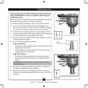
...with wiring, use the wire connectors provided. 4-3. Connect the white wire (grounded) from the ceiling to the white wire (grounded) from the fan. 4-4. Spread the wires apart, with national and local electrical codes. 4-1. Before attempting installation, make sure the power is still off. 4-2.... Wire Connector 8 45049-01 • 07/13/09 • Hunter Fan Company If you are unfamiliar with national and local electrical codes and ANSI/NFPA 70. For all these connections use a qualified electrician. Connect...
...with wiring, use the wire connectors provided. 4-3. Connect the white wire (grounded) from the ceiling to the white wire (grounded) from the fan. 4-4. Spread the wires apart, with national and local electrical codes. 4-1. Before attempting installation, make sure the power is still off. 4-2.... Wire Connector 8 45049-01 • 07/13/09 • Hunter Fan Company If you are unfamiliar with national and local electrical codes and ANSI/NFPA 70. For all these connections use a qualified electrician. Connect...
Owner's Manual
Page 9
... remove the canopy trim ring, follow these steps: 1. Hanger Bracket Canopy Trim Ring Step 5-4 Step 5-3 Step 5-5 Canopy Screw 9 45049-01 • 07/13/09 • Hunter Fan Company 5 • Installing the Canopy and Canopy Trim Ring 5-1. Steps 5-1 - 5-2 Canopy Should you need to secure the canopy. Partially install two canopy screws (about 2 full...
... remove the canopy trim ring, follow these steps: 1. Hanger Bracket Canopy Trim Ring Step 5-4 Step 5-3 Step 5-5 Canopy Screw 9 45049-01 • 07/13/09 • Hunter Fan Company 5 • Installing the Canopy and Canopy Trim Ring 5-1. Steps 5-1 - 5-2 Canopy Should you need to secure the canopy. Partially install two canopy screws (about 2 full...

Owner's Manual
Page 10
6 • Assembling the Blades Hunter fans use several styles of fan blade irons (brackets that hold the blade to a blade iron using three blade assembly screws. Your fan may appear slightly loose after screws are installed in the motor to the fan. If you used grommets, the...with grommet Blade Assembly Screws Steps 6-1 - 6-2 Use without grommet Blade Mounting Screw Step 6-4 10 45049-01 • 07/13/09 • Hunter Fan Company This is normal. 6-3. Insert the second blade mounting screw, then securely tighten both mounting screws. Note: Some blade mounting screws are tightened....
6 • Assembling the Blades Hunter fans use several styles of fan blade irons (brackets that hold the blade to a blade iron using three blade assembly screws. Your fan may appear slightly loose after screws are installed in the motor to the fan. If you used grommets, the...with grommet Blade Assembly Screws Steps 6-1 - 6-2 Use without grommet Blade Mounting Screw Step 6-4 10 45049-01 • 07/13/09 • Hunter Fan Company This is normal. 6-3. Insert the second blade mounting screw, then securely tighten both mounting screws. Note: Some blade mounting screws are tightened....
Owner's Manual
Page 11
Install the remaining screw into the switch housing mounting plate. 7-2. Steps 7-1 - 7-4 Housing Assembly Screw Upper Switch Housing 11 45049-01 • 07/13/09 • Hunter Fan Company Feed the upper plug connector through the center opening of the keyhole slots. Align the keyhole slots in the switch housing fixture falling. Failure ...
Install the remaining screw into the switch housing mounting plate. 7-2. Steps 7-1 - 7-4 Housing Assembly Screw Upper Switch Housing 11 45049-01 • 07/13/09 • Hunter Fan Company Feed the upper plug connector through the center opening of the keyhole slots. Align the keyhole slots in the switch housing fixture falling. Failure ...
Owner's Manual
Page 12
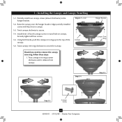
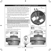
Lower Switch Housing Threaded Rod Steps 7-5 - 7-6 Wires Light Kit/ Speaker Steps 7-8 - 7-9 Note: Align the fan pull chain with the chain guide. 7-8. Feed the two wires from the light kit/speaker assembly into the center hole in the lower switch housing. 7-7. ...Insert the threaded rod from the light kit up with the chain guide. 12 45049-01 • 07/13/09 • Hunter Fan Company Install the nut and washer onto the threaded rod from the light kit/speaker assembly. 7-10.Remove the wire connectors from the two wires...
Lower Switch Housing Threaded Rod Steps 7-5 - 7-6 Wires Light Kit/ Speaker Steps 7-8 - 7-9 Note: Align the fan pull chain with the chain guide. 7-8. Feed the two wires from the light kit/speaker assembly into the center hole in the lower switch housing. 7-7. ...Insert the threaded rod from the light kit up with the chain guide. 12 45049-01 • 07/13/09 • Hunter Fan Company Install the nut and washer onto the threaded rod from the light kit/speaker assembly. 7-10.Remove the wire connectors from the two wires...
Owner's Manual
Page 13
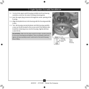
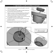
...the third housing assembly screw. 7-16.Tighten all wire connections using wire connectors. 7-12.To attach the lower switch housing assembly to the fan, partially install two housing assembly screws into the upper switch housing. 7-13.Connect the upper plug connector from the motor to the lower plug... Housing Assembly Screw Lower Switch Housing Notch Steps 7-14 - 7-16 Steps 7-12 - 7-15 13 45049-01 • 07/13/09 • Hunter Fan Company Twist the lower switch housing and the light kit/speaker assembly clockwise to the white wire from the light kit. 7 • Light/Speaker Assembly...
...the third housing assembly screw. 7-16.Tighten all wire connections using wire connectors. 7-12.To attach the lower switch housing assembly to the fan, partially install two housing assembly screws into the upper switch housing. 7-13.Connect the upper plug connector from the motor to the lower plug... Housing Assembly Screw Lower Switch Housing Notch Steps 7-14 - 7-16 Steps 7-12 - 7-15 13 45049-01 • 07/13/09 • Hunter Fan Company Twist the lower switch housing and the light kit/speaker assembly clockwise to the white wire from the light kit. 7 • Light/Speaker Assembly...
Owner's Manual
Page 14
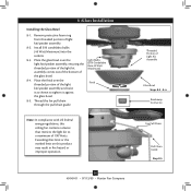
..., this product may result in fire hazard or improper operation. 14 45049-01 • 07/13/09 • Hunter Fan Company Threaded Portion of 190 Watts. Thread the fan pull chain through the pull chain guide. Install B10 candelabra bulbs (40 Watt Maximum) into the sockets. 8-3. Exceeding ...that limit or the marked limit on this ceiling fan contains a device that restricts the light kit to tighten it against the glass bowl. 8-5. Remove protective foam ring from threaded portion of ...
..., this product may result in fire hazard or improper operation. 14 45049-01 • 07/13/09 • Hunter Fan Company Threaded Portion of 190 Watts. Thread the fan pull chain through the pull chain guide. Install B10 candelabra bulbs (40 Watt Maximum) into the sockets. 8-3. Exceeding ...that limit or the marked limit on this ceiling fan contains a device that restricts the light kit to tighten it against the glass bowl. 8-5. Remove protective foam ring from threaded portion of ...
Owner's Manual
Page 15
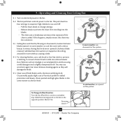
...Clean wood finish blades with a direct breeze. Clean painted and high-gloss blades in warm weather to the fan. 9-2. Reversing Switch 15 45049-01 • 07/13/09 • Hunter Fan Company A vacuum cleaner brush nozzle can remove heavier dust. For cleaning finishes, use upward air flow pattern... To Change Airflow Direction Turn the fan off and let it come to prevent the chain from recoiling into...
...Clean wood finish blades with a direct breeze. Clean painted and high-gloss blades in warm weather to the fan. 9-2. Reversing Switch 15 45049-01 • 07/13/09 • Hunter Fan Company A vacuum cleaner brush nozzle can remove heavier dust. For cleaning finishes, use upward air flow pattern... To Change Airflow Direction Turn the fan off and let it come to prevent the chain from recoiling into...
Owner's Manual
Page 16
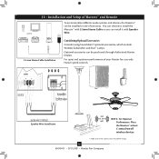
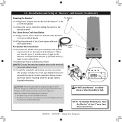
...Maestro™ at least 5' away from all wireless devices. 16 45049-01 • 07/13/09 • Hunter Fan Company 10 • Installation and Setup of Maestro™ and Remote To accommodate different audio systems and devices, ...the Maestro™ can be purchased through Authorized Hunter Dealers. Speaker Wire Installation 300ft (Max. Optional accessories can install it with Speaker Wire. 3.5 mm Stereo Cable...5mm Stereo Cable or you can be installed in one of your Hunter fan, use only Hunter speed controls.
...Maestro™ at least 5' away from all wireless devices. 16 45049-01 • 07/13/09 • Hunter Fan Company 10 • Installation and Setup of Maestro™ and Remote To accommodate different audio systems and devices, ...the Maestro™ can be purchased through Authorized Hunter Dealers. Speaker Wire Installation 300ft (Max. Optional accessories can install it with Speaker Wire. 3.5 mm Stereo Cable...5mm Stereo Cable or you can be installed in one of your Hunter fan, use only Hunter speed controls.
Owner's Manual
Page 17
... speaker input terminals on your audio device. 10-6.Make sure that all wireless devices. 17 45049-01 • 07/13/09 • Hunter Fan Company Make sure that may not cause harmful interference. 2. Operation is high. DO NOT put Maestro™ in the port labeled power. ...Maestro™ 10-2.Select the correct channel by Hunter Fan Company could void your local battery recycling center for use with the remote control transmitter. This device must accept any interference received, including ...
... speaker input terminals on your audio device. 10-6.Make sure that all wireless devices. 17 45049-01 • 07/13/09 • Hunter Fan Company Make sure that may not cause harmful interference. 2. Operation is high. DO NOT put Maestro™ in the port labeled power. ...Maestro™ 10-2.Select the correct channel by Hunter Fan Company could void your local battery recycling center for use with the remote control transmitter. This device must accept any interference received, including ...
Owner's Manual
Page 18
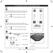
... will switch the surround sound function between: LED Indicators R Right Channel L Left Channel M Mixed Channel LED Indicators 18 45049-01 • 07/13/09 • Hunter Fan Company
... will switch the surround sound function between: LED Indicators R Right Channel L Left Channel M Mixed Channel LED Indicators 18 45049-01 • 07/13/09 • Hunter Fan Company
Owner's Manual
Page 19
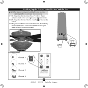
... Channel 1 Channel Selection Switch Channel 2 Channel 3 Channel 4 19 45049-01 • 07/13/09 • Hunter Fan Company 12 • Changing the channel on the Maestro™ and the Fan NOTE:The Maestro™ transmitter and the fan must be on the same channel to transmit and receive properly. 12-1.To change the channel... on the Maestro™, slide the channel selection switch on the lower right corner of the transmitter. 12-2.To change the channel on the fan press the button on the remote. 12-3 The green/red LED indicators on the bottom of the...
... Channel 1 Channel Selection Switch Channel 2 Channel 3 Channel 4 19 45049-01 • 07/13/09 • Hunter Fan Company 12 • Changing the channel on the Maestro™ and the Fan NOTE:The Maestro™ transmitter and the fan must be on the same channel to transmit and receive properly. 12-1.To change the channel... on the Maestro™, slide the channel selection switch on the lower right corner of the transmitter. 12-2.To change the channel on the fan press the button on the remote. 12-3 The green/red LED indicators on the bottom of the...
Owner's Manual
Page 20
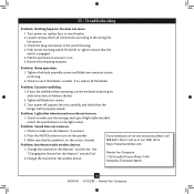
... at http://www.hunterfan.com. 1. Change the channel on the Maestro™ and the fan. fan does not move. 1. Push motor reversing switch firmly left or right to turn on the speaker. Hunter Fan Company 7130 Goodlett Farms Pkwy. # 400 Memphis, Tennessee 38016 20 45049-01 • ...07/13/09 • Hunter Fan Company Remove the shipping bumpers. If your fan wobbles when operating, use the enclosed balancing kit and instructions ...
... at http://www.hunterfan.com. 1. Change the channel on the Maestro™ and the fan. fan does not move. 1. Push motor reversing switch firmly left or right to turn on the speaker. Hunter Fan Company 7130 Goodlett Farms Pkwy. # 400 Memphis, Tennessee 38016 20 45049-01 • ...07/13/09 • Hunter Fan Company Remove the shipping bumpers. If your fan wobbles when operating, use the enclosed balancing kit and instructions ...


