
Installation Guide
Page 1
... washers through the inner holes of 1/16" into the ceiling. 3-2. Wiring o e electrical cable is a ceiling joist directly above the floor and the ceiling is recessed a minimum of 1/16" into the ceiling. Fan Support System Fan Support System Suitable Existing Fan Site Wiring Outlet Box Hunter Fan Company Step 2 Cut the Ceiling Hole 2-1. If NOT, install a support brace as described...
... washers through the inner holes of 1/16" into the ceiling. 3-2. Wiring o e electrical cable is a ceiling joist directly above the floor and the ceiling is recessed a minimum of 1/16" into the ceiling. Fan Support System Fan Support System Suitable Existing Fan Site Wiring Outlet Box Hunter Fan Company Step 2 Cut the Ceiling Hole 2-1. If NOT, install a support brace as described...
Owner's Manual
Page 1
installation and operation manual for Hunter Ceiling Fans TYPE 3 Models 42700-01 • 01/15/08 For Your Records and Warranty Assistance Model Name Catalog/Model No Serial No Date Purchased Where Purchased For reference also attach your receipt or a copy of your receipt to the manual.
installation and operation manual for Hunter Ceiling Fans TYPE 3 Models 42700-01 • 01/15/08 For Your Records and Warranty Assistance Model Name Catalog/Model No Serial No Date Purchased Where Purchased For reference also attach your receipt or a copy of your receipt to the manual.
Owner's Manual
Page 2
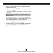
...; Operating the Remote Control and Mounting the Holder 14 11 • Operating and Cleaning Your Ceiling Fan 15 12 • Troubleshooting 16 Welcome Your new Hunter® ceiling fan is an addition to the outlet box and associated wall switch location. If you complete instructions ...for your fan, disconnect the power by turning off position, securely fasten a prominent warning device, such as a tag...
...; Operating the Remote Control and Mounting the Holder 14 11 • Operating and Cleaning Your Ceiling Fan 15 12 • Troubleshooting 16 Welcome Your new Hunter® ceiling fan is an addition to the outlet box and associated wall switch location. If you complete instructions ...for your fan, disconnect the power by turning off position, securely fasten a prominent warning device, such as a tag...
Owner's Manual
Page 3
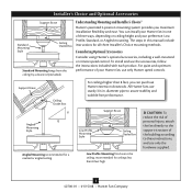
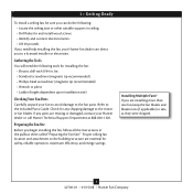
... Profile Mounting fits close to these instructions, and use only Hunter speed controls. The steps in . Understanding Mounting and Installer's Choice® Hunter's patented 3-position mounting system provides you can install your Hunter fan in one of three ways, depending on ceiling height and your Hunter fan, use only the hardware supplied. 3 42700-01 • 01/15...
... Profile Mounting fits close to these instructions, and use only Hunter speed controls. The steps in . Understanding Mounting and Installer's Choice® Hunter's patented 3-position mounting system provides you can install your Hunter fan in one of three ways, depending on ceiling height and your Hunter fan, use only the hardware supplied. 3 42700-01 • 01/15...
Owner's Manual
Page 4
... damaged, contact your Hunter dealer or call Hunter Technical Support Department at 888-830-1326. Installing Multiple Fans? Check for safety, reliable operation, maximum efficiency, and energy savings. If you need the following : • Locate the ceiling joist or other suitable support in the pullout sheet called "Preparing the Fan Site." Proper ceiling fan location and attachment...
... damaged, contact your Hunter dealer or call Hunter Technical Support Department at 888-830-1326. Installing Multiple Fans? Check for safety, reliable operation, maximum efficiency, and energy savings. If you need the following : • Locate the ceiling joist or other suitable support in the pullout sheet called "Preparing the Fan Site." Proper ceiling fan location and attachment...
Owner's Manual
Page 5
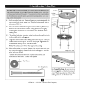
... 9/64 in. pilot holes; Note: The isolators should have a diameter of the threaded screw holes in the ceiling plate are on the lower side. 5 42700-01 • 01/15/08 • Hunter Fan Company Do not over tighten. Isolator Ceiling Plate Flat Washer Step 2-2 Steps 2-3 - 2-5 3 in. The pilot holes should be flush against the...
... 9/64 in. pilot holes; Note: The isolators should have a diameter of the threaded screw holes in the ceiling plate are on the lower side. 5 42700-01 • 01/15/08 • Hunter Fan Company Do not over tighten. Isolator Ceiling Plate Flat Washer Step 2-2 Steps 2-3 - 2-5 3 in. The pilot holes should be flush against the...
Owner's Manual
Page 8
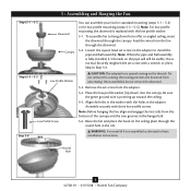
...canopy and the two grooves in these installation instructions. Round Hole 8 42700-01 • 01/15/08 • Hunter Fan Company Feed the wires from the fan through the canopy. Remove the set screw with three low profile screws. Note: For low profile mounting, the downrod ...is normal. Note: When the pipe and ball assembly is pointing up toward the ceiling. 5-5. To assemble fan to hang down ) into the canopy. Securely retighten the set screw from a flat or angled ceiling, insert the downrod through the downrod. 5-2. Assemble securely with a wrench or pliers....
...canopy and the two grooves in these installation instructions. Round Hole 8 42700-01 • 01/15/08 • Hunter Fan Company Feed the wires from the fan through the canopy. Remove the set screw with three low profile screws. Note: For low profile mounting, the downrod ...is normal. Note: When the pipe and ball assembly is pointing up toward the ceiling. 5-5. To assemble fan to hang down ) into the canopy. Securely retighten the set screw from a flat or angled ceiling, insert the downrod through the downrod. 5-2. Assemble securely with a wrench or pliers....
Owner's Manual
Page 10
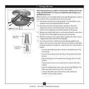
If you are unfamiliar with a white stripe from the receiver. • Connect the white wire from the fan to the black wire with wiring, use switch in the ceiling plate. 7-5. Disconnect the power by turning off the circuit breakers to each side and feed the wires from the receiver. 10 42700-01... • 01/15/08 • Hunter Fan Company Place the receiver inside the canopy, making sure that the ...
If you are unfamiliar with a white stripe from the receiver. • Connect the white wire from the fan to the black wire with wiring, use switch in the ceiling plate. 7-5. Disconnect the power by turning off the circuit breakers to each side and feed the wires from the receiver. 10 42700-01... • 01/15/08 • Hunter Fan Company Place the receiver inside the canopy, making sure that the ...
Owner's Manual
Page 11
... no bare wire or wire strands are visible after making connections. 7-7. Push all wires and wire connectors back through one of the slots in the ceiling plate. (For best reception, make sure the end of the antenna is exposed at the top of the canopy.) 7-8. Run the thin white antenna wire... from the other wires. 11 42700-01 • 01/15/08 • Hunter Fan Company Place the green and white wires on a separate side of the outlet box from the receiver through the...
... no bare wire or wire strands are visible after making connections. 7-7. Push all wires and wire connectors back through one of the slots in the ceiling plate. (For best reception, make sure the end of the antenna is exposed at the top of the canopy.) 7-8. Run the thin white antenna wire... from the other wires. 11 42700-01 • 01/15/08 • Hunter Fan Company Place the green and white wires on a separate side of the outlet box from the receiver through the...
Owner's Manual
Page 12
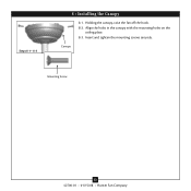
Canopy Mounting Screw 12 42700-01 • 01/15/08 • Hunter Fan Company Steps 8-1- 8-3 8 • Installing the Canopy 8-1. Insert and tighten the mounting screws securely. Holding the canopy, raise the fan off the hook. 8-2. Align the holes in the canopy with the mounting holes on the ceiling plate. 8-3.
Canopy Mounting Screw 12 42700-01 • 01/15/08 • Hunter Fan Company Steps 8-1- 8-3 8 • Installing the Canopy 8-1. Insert and tighten the mounting screws securely. Holding the canopy, raise the fan off the hook. 8-2. Align the holes in the canopy with the mounting holes on the ceiling plate. 8-3.
Owner's Manual
Page 15
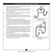
...cleaning finishes, use upward air flow pattern 15 42700-01 • 01/15/08 • Hunter Fan Company Occasionally, apply a light coat of furniture polish for 5 seconds, then back on at the ceiling around the room without the remote, turn the wall switch OFF. 11-3. Remove surface smudges ...speed. Note: For everyday operation, leave the wall switch ON. Clean painted and high-gloss blades in warm weather to prevent scratching. Ceiling fans work best by blowing air downward (counterclockwise blade rotation) in the same manner as they will not be used for 5 days or ...
...cleaning finishes, use upward air flow pattern 15 42700-01 • 01/15/08 • Hunter Fan Company Occasionally, apply a light coat of furniture polish for 5 seconds, then back on at the ceiling around the room without the remote, turn the wall switch OFF. 11-3. Remove surface smudges ...speed. Note: For everyday operation, leave the wall switch ON. Clean painted and high-gloss blades in warm weather to prevent scratching. Ceiling fans work best by blowing air downward (counterclockwise blade rotation) in the same manner as they will not be used for 5 days or ...
Parts Guide
Page 1
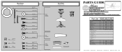
...the box. REFER TO THE INSTALLATION MANUAL FOR FULL ASSEMBLY INSTRUCTIONS. Part List Item Name Ceiling Plate Canopy Hanger Pipe Assembly Housing, Top Light Kit Assembly Globe/Shade Bulb Globe Trim ...01 63722-25 92542-01 94245-01 94246-01 85219-01 94242-01 76238-57 98988-00-860 21628 98988-02 Brushed Bronze Part # 84050-01 84005-01 63722-25 92542-01 94245-01 94246-01... 07570-01 1 87108-01 87108-01 1 87075-01 87075-01 1 85095-03 85095-03 1 85093-01 85093-01 Hunter Fan Company • 2500 Frisco Avenue • Memphis, TN 38114 • www.hunterfan.com • 98000-01-938 11...
...the box. REFER TO THE INSTALLATION MANUAL FOR FULL ASSEMBLY INSTRUCTIONS. Part List Item Name Ceiling Plate Canopy Hanger Pipe Assembly Housing, Top Light Kit Assembly Globe/Shade Bulb Globe Trim ...01 63722-25 92542-01 94245-01 94246-01 85219-01 94242-01 76238-57 98988-00-860 21628 98988-02 Brushed Bronze Part # 84050-01 84005-01 63722-25 92542-01 94245-01 94246-01... 07570-01 1 87108-01 87108-01 1 87075-01 87075-01 1 85095-03 85095-03 1 85093-01 85093-01 Hunter Fan Company • 2500 Frisco Avenue • Memphis, TN 38114 • www.hunterfan.com • 98000-01-938 11...


