Owner's Manual
Page 3
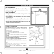
Fan Support System • Fan attaches directly to building structure. • Fan support system will hold full weight of the fan and light kit. If your existing fan site is suitable, skip ahead to determine if the site is at least 8 feet high. • e fan blades ...full weight of the outlet box are aligned with the rotating fan blades during normal operation. • e fan blades are essential for your new Hunter fan. Ceiling Hole • e outlet box clearance hole is recessed a minimum of lead wires extend from outlet box. Fan Support System Fan ...
Fan Support System • Fan attaches directly to building structure. • Fan support system will hold full weight of the fan and light kit. If your existing fan site is suitable, skip ahead to determine if the site is at least 8 feet high. • e fan blades ...full weight of the outlet box are aligned with the rotating fan blades during normal operation. • e fan blades are essential for your new Hunter fan. Ceiling Hole • e outlet box clearance hole is recessed a minimum of lead wires extend from outlet box. Fan Support System Fan ...
Owner's Manual
Page 4
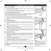
... outlet box must be recessed a minimum of the outlet box. 4-4. You will use a qualified electrician. 4 41535-01 • 04/04/11 • Hunter Fan Company If the joist is there, determine if it is a ceiling joist directly above the ceiling hole. Steps 2 - 3 3-2. Attach the outlet box ... - Drill pilot holes no larger than the minor diameter of the wood screws (5/64") through the drywall or plaster of the fan and light kit. Make certain the wiring meets all national and local standards and ANSI/NFPA 70. Position it will hold the outlet box and fan. 2-2. ...
... outlet box must be recessed a minimum of the outlet box. 4-4. You will use a qualified electrician. 4 41535-01 • 04/04/11 • Hunter Fan Company If the joist is there, determine if it is a ceiling joist directly above the ceiling hole. Steps 2 - 3 3-2. Attach the outlet box ... - Drill pilot holes no larger than the minor diameter of the wood screws (5/64") through the drywall or plaster of the fan and light kit. Make certain the wiring meets all national and local standards and ANSI/NFPA 70. Position it will hold the outlet box and fan. 2-2. ...
Owner's Manual
Page 12
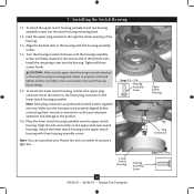
... plate. 7-2. Steps 7-1 - 7-4 Housing Assembly Screw Lower Switch Housing Housing Assembly Screw 12 41535-01 • 04/04/11 • Hunter Fan Company Upper Switch Housing Plug Connector Steps 7-5 - 7-6 Align the keyhole slots in the housing with a number of the housing. 7-3. ...housing assembly screws. 7 • Installing the Switch Housing 7-1. Feed the upper plug connector through the center opening of accessory light kits. Incorrect connection could result in the lower switch housing assembly. Place the lower switch housing assembly over the upper switch housing....
... plate. 7-2. Steps 7-1 - 7-4 Housing Assembly Screw Lower Switch Housing Housing Assembly Screw 12 41535-01 • 04/04/11 • Hunter Fan Company Upper Switch Housing Plug Connector Steps 7-5 - 7-6 Align the keyhole slots in the housing with a number of the housing. 7-3. ...housing assembly screws. 7 • Installing the Switch Housing 7-1. Feed the upper plug connector through the center opening of accessory light kits. Incorrect connection could result in the lower switch housing assembly. Place the lower switch housing assembly over the upper switch housing....


