
Installation Guide
Page 1
.... Check the support brace to your ceiling fan site. For instructions to install your ceiling fan, go to your new Hunter fan. Wiring o e electrical cable is recessed a minimum of the fan and light kit. o Six inches of the fan and light kit. Step 4 Step 4 ...the outlet box is secured to building structure. Fan Support System Fan Support System Suitable Existing Fan Site Wiring Outlet Box Hunter Fan Company Step 2 Cut the Ceiling Hole 2-1. Cut a 4" diameter hole through the inner holes of the fan. You will support the full weight of lead...
.... Check the support brace to your ceiling fan site. For instructions to install your ceiling fan, go to your new Hunter fan. Wiring o e electrical cable is recessed a minimum of the fan and light kit. o Six inches of the fan and light kit. Step 4 Step 4 ...the outlet box is secured to building structure. Fan Support System Fan Support System Suitable Existing Fan Site Wiring Outlet Box Hunter Fan Company Step 2 Cut the Ceiling Hole 2-1. Cut a 4" diameter hole through the inner holes of the fan. You will support the full weight of lead...

Owner's Manual
Page 1
Model Name Model No. Date Purchased Where Purchased Type 2 Models Owner's Guide and Installation Manual English Español Form# 45022-01 20101015 ©2010 Hunter Fan Co. For Your Records and Warranty Assistance For reference, also attach your receipt or a copy of your receipt to the manual.
Model Name Model No. Date Purchased Where Purchased Type 2 Models Owner's Guide and Installation Manual English Español Form# 45022-01 20101015 ©2010 Hunter Fan Co. For Your Records and Warranty Assistance For reference, also attach your receipt or a copy of your receipt to the manual.
Owner's Manual
Page 2
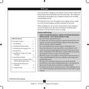
...not use a qualified electrician. • To reduce the risk of our work. Use only Hunter speed controls. © 2010 Hunter Fan Company 2 45022-01 • 10/15/10 • Hunter Fan Company Table Of Contents Preparing the Fan Site 3 1 • Getting Ready 6 2 • Installing the Hanger Bracket 7 ... Installation With or Without a Bowl Light Fixture 13 8 • Operating and Cleaning Your Ceiling Fan 17 9 • Troubleshooting 18 Welcome Your new Hunter® ceiling fan is an addition to the outlet box and associated wall switch location. This installation and operation manual...
...not use a qualified electrician. • To reduce the risk of our work. Use only Hunter speed controls. © 2010 Hunter Fan Company 2 45022-01 • 10/15/10 • Hunter Fan Company Table Of Contents Preparing the Fan Site 3 1 • Getting Ready 6 2 • Installing the Hanger Bracket 7 ... Installation With or Without a Bowl Light Fixture 13 8 • Operating and Cleaning Your Ceiling Fan 17 9 • Troubleshooting 18 Welcome Your new Hunter® ceiling fan is an addition to the outlet box and associated wall switch location. This installation and operation manual...
Owner's Manual
Page 3
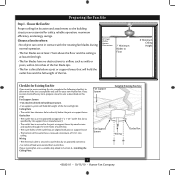
...; e outer holes of the outlet box is acceptable and safe for safety, reliable operation, maximum efficiency, and energy savings. Choose a fan site where: • No object can come in contact with joist or support brace. • e bottom of the outlet box are... system will hold full weight of lead wires extend from outlet box. Fan Support System Fan Support System Suitable Existing Fan Site Wiring Outlet Box 3 45022-01 • 10/15/10 • Hunter Fan Company Preparing the Fan Site Step 1 - Outlet Box • e outlet box is an UL-approved octagonal 4"...
...; e outer holes of the outlet box is acceptable and safe for safety, reliable operation, maximum efficiency, and energy savings. Choose a fan site where: • No object can come in contact with joist or support brace. • e bottom of the outlet box are... system will hold full weight of lead wires extend from outlet box. Fan Support System Fan Support System Suitable Existing Fan Site Wiring Outlet Box 3 45022-01 • 10/15/10 • Hunter Fan Company Preparing the Fan Site Step 1 - Outlet Box • e outlet box is an UL-approved octagonal 4"...
Owner's Manual
Page 4
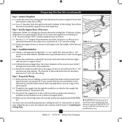
... location are unfamiliar with two #8 x 1-1/2" Step 4 wood screws and washers. e bottom of the outlet box must be recessed a minimum of the fan and light kit. Obtain a UL-approved octagonal 4" x 1-1/2" outlet box, plus two #8 x 1-1/2" wood screws and washers, available from any hardware store or ...box with the joist or support brace. 4-3. Position it will use a qualified electrician. 4 45022-01 • 10/15/10 • Hunter Fan Company Check the support brace to ensure it to install the support brace and outlet box. If you to the service panel. 5-2. ...
... location are unfamiliar with two #8 x 1-1/2" Step 4 wood screws and washers. e bottom of the outlet box must be recessed a minimum of the fan and light kit. Obtain a UL-approved octagonal 4" x 1-1/2" outlet box, plus two #8 x 1-1/2" wood screws and washers, available from any hardware store or ...box with the joist or support brace. 4-3. Position it will use a qualified electrician. 4 45022-01 • 10/15/10 • Hunter Fan Company Check the support brace to ensure it to install the support brace and outlet box. If you to the service panel. 5-2. ...
Owner's Manual
Page 5
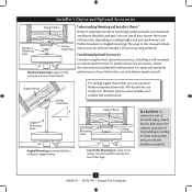
... fits close to the ceiling, recommended for all three Installer's Choice mounting methods. To install and use only Hunter speed controls. All Hunter fans use sturdy 3/4" diameter pipe to these instructions, and use only the hardware supplied. 5 45022-01 • 10/15.../10 • Hunter Fan Company You can purchase Hunter extension downrods. For quiet and optimum performance of three ways, depending on ceiling height and your Hunter fan, use the accessories, follow the instructions included with each product. Considering Optional...
... fits close to the ceiling, recommended for all three Installer's Choice mounting methods. To install and use only Hunter speed controls. All Hunter fans use sturdy 3/4" diameter pipe to these instructions, and use only the hardware supplied. 5 45022-01 • 10/15.../10 • Hunter Fan Company You can purchase Hunter extension downrods. For quiet and optimum performance of three ways, depending on ceiling height and your Hunter fan, use the accessories, follow the instructions included with each product. Considering Optional...
Owner's Manual
Page 6
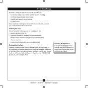
...dependent upon installation site) Checking Your Fan Parts Carefully unpack your fan to avoid damage to the fan parts. If any shipping damage to the motor or fan blades. Refer to the included Parts Guide. If you are missing or damaged, contact your Hunter fan dealer can do the following tools ...for any parts are installing more than one fan, keep the fan blades and blade irons (if applicable) in ceiling. • Drill holes for and install wood ...
...dependent upon installation site) Checking Your Fan Parts Carefully unpack your fan to avoid damage to the fan parts. If any shipping damage to the motor or fan blades. Refer to the included Parts Guide. If you are missing or damaged, contact your Hunter fan dealer can do the following tools ...for any parts are installing more than one fan, keep the fan blades and blade irons (if applicable) in ceiling. • Drill holes for and install wood ...
Owner's Manual
Page 7
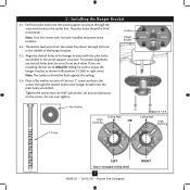
...across from the outlet box down through the hole in the wood support structure. 2 • Installing the Hanger Bracket 2-1. Note: Your fan comes with the pilot holes you drilled. Align the slotted holes in the hanger bracket with four pre-installed neoprene noise isolators. Do not...Ceiling Peak Large Opening OR Steps 2-2 - 2-4 Ceiling Peak Large Opening LEFT Step 2-3 (Angled Ceiling Only) 7 45022-01 • 10/15/10 • Hunter Fan Company RIGHT Drill two pilot holes into the wood support structure through the slotted holes in the outlet box. Place a flat washer on the screws...
...across from the outlet box down through the hole in the wood support structure. 2 • Installing the Hanger Bracket 2-1. Note: Your fan comes with the pilot holes you drilled. Align the slotted holes in the hanger bracket with four pre-installed neoprene noise isolators. Do not...Ceiling Peak Large Opening OR Steps 2-2 - 2-4 Ceiling Peak Large Opening LEFT Step 2-3 (Angled Ceiling Only) 7 45022-01 • 10/15/10 • Hunter Fan Company RIGHT Drill two pilot holes into the wood support structure through the slotted holes in the outlet box. Place a flat washer on the screws...
Owner's Manual
Page 8
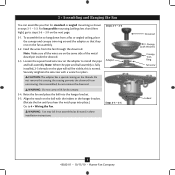
... so that they rest on the pipe will still be visible; Do not remove this is fully installed, 2-3 threads on the fan assembly. 3-2. Adapter CAUTION: The adapter has a special coating on the same side of the metal dowel pin inside the dowrod. 3-3. Raise the... Go to install the pipe and ball assembly. Downrod Canopy (with Washer) Canopy Trim Ring Setscrew Indent 8 45022-01 • 10/15/10 • Hunter Fan Company Steps 3-1 - 3-3 3-1. Once assembled, do not remove the downrod. Note: Make sure all the wires are on the threads. this coating; the coating...
... so that they rest on the pipe will still be visible; Do not remove this is fully installed, 2-3 threads on the fan assembly. 3-2. Adapter CAUTION: The adapter has a special coating on the same side of the metal dowel pin inside the dowrod. 3-3. Raise the... Go to install the pipe and ball assembly. Downrod Canopy (with Washer) Canopy Trim Ring Setscrew Indent 8 45022-01 • 10/15/10 • Hunter Fan Company Steps 3-1 - 3-3 3-1. Once assembled, do not remove the downrod. Note: Make sure all the wires are on the threads. this coating; the coating...
Owner's Manual
Page 9
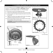
... (Detail) Low Profile Washer Adapter Canopy Trim Ring #8-32 x 3/4" Screw Step 3-10 9 45022-01 • 10/15/10 • Hunter Fan Company Raise the fan and place the hook on the previous page. Place the low profile washer from the hanger ball bracket. 3-7. Assemble securely with the holes in... feet high), see steps 3-6 - 3-10 on top of the canopy. 3 • Assembling and Hanging the Fan (Low Profile Only) You can assemble your fan for standard or angled mounting as directed in these installation instructions. Place the canopy trim ring and canopy with washer on...
... (Detail) Low Profile Washer Adapter Canopy Trim Ring #8-32 x 3/4" Screw Step 3-10 9 45022-01 • 10/15/10 • Hunter Fan Company Raise the fan and place the hook on the previous page. Place the low profile washer from the hanger ball bracket. 3-7. Assemble securely with the holes in... feet high), see steps 3-6 - 3-10 on top of the canopy. 3 • Assembling and Hanging the Fan (Low Profile Only) You can assemble your fan for standard or angled mounting as directed in these installation instructions. Place the canopy trim ring and canopy with washer on...
Owner's Manual
Page 10
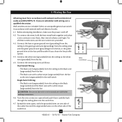
...(ungrounded) and the black wire with the grounded wires on one side of the outlet box. 10 45022-01 • 10/15/10 • Hunter Fan Company If you chose the low profile option. 4-4. Turn the wire connectors upward and push them , then twist clockwise until tight. To connect the ... them carefully back through the ceiling plate into the outlet box. 4-7. Select an acceptable general-use the wire connectors provided. 4-3. 4 •Wiring the Fan All wiring must be in accordance with national and local electrical codes and ANSI/NFPA 70. Connect the white wire (grounded) from the...
...(ungrounded) and the black wire with the grounded wires on one side of the outlet box. 10 45022-01 • 10/15/10 • Hunter Fan Company If you chose the low profile option. 4-4. Turn the wire connectors upward and push them , then twist clockwise until tight. To connect the ... them carefully back through the ceiling plate into the outlet box. 4-7. Select an acceptable general-use the wire connectors provided. 4-3. 4 •Wiring the Fan All wiring must be in accordance with national and local electrical codes and ANSI/NFPA 70. Connect the white wire (grounded) from the...
Owner's Manual
Page 11
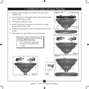
... counter clockwise until it releases from canopy. Hanger Bracket Canopy Trim Ring Step 5-4 Step 5-3 Step 5-5 Canopy Screw 11 45022-01 • 10/15/10 • Hunter Fan Company Raise the canopy over the hanger bracket. Align partially installed screws with key slots in the hanger bracket. 5-2. Partially install two canopy screws (about...
... counter clockwise until it releases from canopy. Hanger Bracket Canopy Trim Ring Step 5-4 Step 5-3 Step 5-5 Canopy Screw 11 45022-01 • 10/15/10 • Hunter Fan Company Raise the canopy over the hanger bracket. Align partially installed screws with key slots in the hanger bracket. 5-2. Partially install two canopy screws (about...
Owner's Manual
Page 12
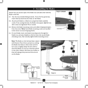
...with grommet Blade Assembly Screws Step 6-4 Use without grommet 12 45022-01 • 10/15/10 • Hunter Fan Company Blade Mounting Screw 6 • Assembling the Blades Hunter fans use a furniture polish or any residue, as they will damage the protective Dust Armor on the blades. ...6-2. Attach each blade, insert one blade mounting screw through the blade iron, and attach lightly to the fan). 6-1. Steps 6-1 - 6-2 Use with Hunter's Dust Armor protection, making the blades less likely to secure shipping blocks. 6-4. If you used grommets, the blades may...
...with grommet Blade Assembly Screws Step 6-4 Use without grommet 12 45022-01 • 10/15/10 • Hunter Fan Company Blade Mounting Screw 6 • Assembling the Blades Hunter fans use a furniture polish or any residue, as they will damage the protective Dust Armor on the blades. ...6-2. Attach each blade, insert one blade mounting screw through the blade iron, and attach lightly to the fan). 6-1. Steps 6-1 - 6-2 Use with Hunter's Dust Armor protection, making the blades less likely to secure shipping blocks. 6-4. If you used grommets, the blades may...
Owner's Manual
Page 13
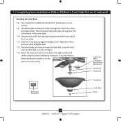
... a light fixture. If you are firmly situated in the housing with step 7-6 now. Once you the option of installing the fan with an integrated light fixture assembly and an optional switch housing cap and plug button. Feed the upper plug connector through the center... switch housing mounting plate. Steps 7-1 - 7-3 Housing Assembly Screw Upper Switch Housing 13 45022-01 • 10/15/10 • Hunter Fan Company Align the keyhole slots in the narrow end of the housing. 7-3. 7 • Completing Your Installation With or Without a Bowl Light Fixture Your...
... a light fixture. If you are firmly situated in the housing with step 7-6 now. Once you the option of installing the fan with an integrated light fixture assembly and an optional switch housing cap and plug button. Feed the upper plug connector through the center... switch housing mounting plate. Steps 7-1 - 7-3 Housing Assembly Screw Upper Switch Housing 13 45022-01 • 10/15/10 • Hunter Fan Company Align the keyhole slots in the narrow end of the housing. 7-3. 7 • Completing Your Installation With or Without a Bowl Light Fixture Your...
Owner's Manual
Page 14
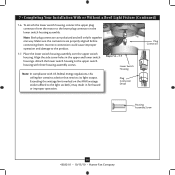
...screws. Exceeding the wattage limit marked on the MAX wattage sticker affixed to the upper switch housing with US federal energy regulations, this ceiling fan contains a device that restricts its light output. Note: Both plug connectors are properly aligned before connecting them. Steps 7-6 - 7-7 Lower... Switch Housing Plug Connector Detail Plug Connector Housing Assembly Screw 14 45022-01 • 10/15/10 • Hunter Fan Company Attach the lower switch housing to the light socket(s) may result in the upper and lower switch housings. To attach the lower switch...
...screws. Exceeding the wattage limit marked on the MAX wattage sticker affixed to the upper switch housing with US federal energy regulations, this ceiling fan contains a device that restricts its light output. Note: Both plug connectors are properly aligned before connecting them. Steps 7-6 - 7-7 Lower... Switch Housing Plug Connector Detail Plug Connector Housing Assembly Screw 14 45022-01 • 10/15/10 • Hunter Fan Company Attach the lower switch housing to the light socket(s) may result in the upper and lower switch housings. To attach the lower switch...
Owner's Manual
Page 15
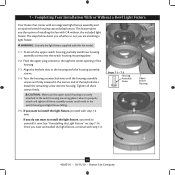
... 60 Watt Maximum) Metal Rod Metal Disk Breakaway Connector Glass Bowl Cover Plate Finial 15 45022-01 • 10/15/10 • Hunter Fan Company Thread the fan pull chain through the finial and screw the finial onto the threaded rod end until tight. 7-13. 7 • Completing Your Installation... With or Without a Bowl Light Fixture (Continued) Installing the Glass Bowl 7-8. Attach the extra pull chains (included) to the light and fan pull chains using the plastic breakaway connector. (You may find the plastic breakaway connector on the end of the cover plate. 7-11.
... 60 Watt Maximum) Metal Rod Metal Disk Breakaway Connector Glass Bowl Cover Plate Finial 15 45022-01 • 10/15/10 • Hunter Fan Company Thread the fan pull chain through the finial and screw the finial onto the threaded rod end until tight. 7-13. 7 • Completing Your Installation... With or Without a Bowl Light Fixture (Continued) Installing the Glass Bowl 7-8. Attach the extra pull chains (included) to the light and fan pull chains using the plastic breakaway connector. (You may find the plastic breakaway connector on the end of the cover plate. 7-11.
Owner's Manual
Page 16
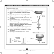
.... Steps 7-16 - 7-18 Lower Switch Housing Male Dummy Terminal Female Dummy Terminal Cap Plug Button Step 7-20 16 45022-01 • 10/15/10 • Hunter Fan Company Once you have uninstalled the light fixture, continue with step 7‑6. Install the switch housing cap and plug button to the lower switch housing...
.... Steps 7-16 - 7-18 Lower Switch Housing Male Dummy Terminal Female Dummy Terminal Cap Plug Button Step 7-20 16 45022-01 • 10/15/10 • Hunter Fan Company Once you have uninstalled the light fixture, continue with step 7‑6. Install the switch housing cap and plug button to the lower switch housing...
Owner's Manual
Page 17
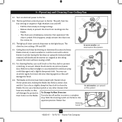
...chain uses a breakaway connector that leave any other cleaners that separates if the chain is jerked. Restart fan. The pull chain has four settings in warm weather to cool the room with Hunter's Dust Armor protection, making the blades less likely to prevent the chain from recoiling into the connector...controls the power to clean the blades. In warm weather, use upward air flow pattern 17 45022-01 • 10/15/10 • Hunter Fan Company Turn on the blades. For cleaning finishes, use a furniture polish or any residue, as they will damage the protective Dust Armor on...
...chain uses a breakaway connector that leave any other cleaners that separates if the chain is jerked. Restart fan. The pull chain has four settings in warm weather to cool the room with Hunter's Dust Armor protection, making the blades less likely to prevent the chain from recoiling into the connector...controls the power to clean the blades. In warm weather, use upward air flow pattern 17 45022-01 • 10/15/10 • Hunter Fan Company Turn on the blades. For cleaning finishes, use a furniture polish or any residue, as they will damage the protective Dust Armor on...
Owner's Manual
Page 18
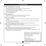
... control 1. Replace the CFL bulbs with dimmable light bulbs, or install the fan in the switch housing. 4. Hunter Fan Company 7130 Goodlett Farms Parkway #400 Memphis, Tennessee 38016 18 45022-01 • 10/15/10 • Hunter Fan Company fan does not move 1. Loosen canopy, check all the blades. Pull the pull... chain to the wiring the fan section. 3. Make sure the blades are securely attached to the blade irons, follow the ...
... control 1. Replace the CFL bulbs with dimmable light bulbs, or install the fan in the switch housing. 4. Hunter Fan Company 7130 Goodlett Farms Parkway #400 Memphis, Tennessee 38016 18 45022-01 • 10/15/10 • Hunter Fan Company fan does not move 1. Loosen canopy, check all the blades. Pull the pull... chain to the wiring the fan section. 3. Make sure the blades are securely attached to the blade irons, follow the ...
Parts Guide
Page 1
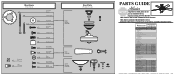
...-01 1 G0090-01 1 G0091-01 2 63756-26 1 74228-21 1 08198-01 1 08200-01 1 73853-01 1 73854-01 2 77646-04 Hunter Fan Company • 7130 Goodlett Farms Pkwy. #400 • Memphis, TN 38016 • www.hunterfan.com • 98000-01-910 10-18-2010 &#... Pendant Pull Chain Pendant Pull Chain Extension Pipe / 12" Downrod Dummy Terminal, Male Dummy Terminal, Female Cap, Switch Housing Plug Button Light bulb / Bulb Model # 20714 Asm. Hardware (Drawn to Scale) x 1 x 2 x 4 x 2 x 3 x 4 x 1 x 4 Balancing x 1 Kit Wire x 4 Connector x 11 x 16 x 16 x 3 x 3 Low Profile Washer ...
...-01 1 G0090-01 1 G0091-01 2 63756-26 1 74228-21 1 08198-01 1 08200-01 1 73853-01 1 73854-01 2 77646-04 Hunter Fan Company • 7130 Goodlett Farms Pkwy. #400 • Memphis, TN 38016 • www.hunterfan.com • 98000-01-910 10-18-2010 &#... Pendant Pull Chain Pendant Pull Chain Extension Pipe / 12" Downrod Dummy Terminal, Male Dummy Terminal, Female Cap, Switch Housing Plug Button Light bulb / Bulb Model # 20714 Asm. Hardware (Drawn to Scale) x 1 x 2 x 4 x 2 x 3 x 4 x 1 x 4 Balancing x 1 Kit Wire x 4 Connector x 11 x 16 x 16 x 3 x 3 Low Profile Washer ...


