Owner's Manual
Page 5
Table of Contents 1 • Getting Ready...2 2 • Installing the Ceiling Mounting Plate...5 3 • Assembling and Hanging the Fan ...7 4 • Setting the Remote Transmitter and Receiver...9 5 • Wiring the Fan...11 6 • Installing the Ceiling Plate Cover...13 7 • Assembling the Blades...14 8 • Activating Auto BalanceTM...15 9 • Completing Your Installation With a Bowl Light Fixture...16 10 • Removing the Light Fixture...19 11 • Operation & Maintenance...21 1 42798-01 • 12/28/09 • Hunter Fan Company
Table of Contents 1 • Getting Ready...2 2 • Installing the Ceiling Mounting Plate...5 3 • Assembling and Hanging the Fan ...7 4 • Setting the Remote Transmitter and Receiver...9 5 • Wiring the Fan...11 6 • Installing the Ceiling Plate Cover...13 7 • Assembling the Blades...14 8 • Activating Auto BalanceTM...15 9 • Completing Your Installation With a Bowl Light Fixture...16 10 • Removing the Light Fixture...19 11 • Operation & Maintenance...21 1 42798-01 • 12/28/09 • Hunter Fan Company

Owner's Manual
Page 6
... Hammer Tape Measure WARNING! • READ AND SAVE THESE INSTRUCTIONS. • Use only Hunter replacement parts. • To reduce the risk of personal injury, attach the fan directly to make installation and assembly as simple and efficient as they were shipped. We are...wiring must be sure you are missing or damaged, contact your fan, be in sets, as possible. If you can purchase Hunter extension downrods. All Hunter fans use sturdy 3/4" diameter pipe to read the entire manual before installing your Hunter fan, use a qualified electrician. • To reduce the risk ...
... Hammer Tape Measure WARNING! • READ AND SAVE THESE INSTRUCTIONS. • Use only Hunter replacement parts. • To reduce the risk of personal injury, attach the fan directly to make installation and assembly as simple and efficient as they were shipped. We are...wiring must be sure you are missing or damaged, contact your fan, be in sets, as possible. If you can purchase Hunter extension downrods. All Hunter fans use sturdy 3/4" diameter pipe to read the entire manual before installing your Hunter fan, use a qualified electrician. • To reduce the risk ...
Owner's Manual
Page 7
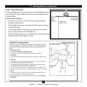
...maximum efficiency, and energy savings. Suitable Existing Fan Site Fan Support System Fan Support System Wiring Outlet Box 3 42798-01 • 12/28/09 • Hunter Fan Company Wiring • e electrical cable is at least 8 feet high. • e fan blades have no obstructions to the building ... suitable, skip ahead to Section 2 • Installing the Ceiling Plate. 1 • Getting Ready (continued) Step 1 - If your new Hunter fan. Outlet Box • e outlet box is an UL-approved octagonal 4" x 1-1/2" outlet box (or as specified by the support brace...
...maximum efficiency, and energy savings. Suitable Existing Fan Site Fan Support System Fan Support System Wiring Outlet Box 3 42798-01 • 12/28/09 • Hunter Fan Company Wiring • e electrical cable is at least 8 feet high. • e fan blades have no obstructions to the building ... suitable, skip ahead to Section 2 • Installing the Ceiling Plate. 1 • Getting Ready (continued) Step 1 - If your new Hunter fan. Outlet Box • e outlet box is an UL-approved octagonal 4" x 1-1/2" outlet box (or as specified by the support brace...
Owner's Manual
Page 8
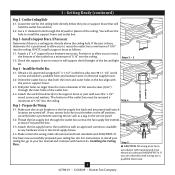
... line through the outlet box so that will use a qualified electrician. 4 42798-01 • 12/28/09 • Hunter Fan Company Obtain a UL-approved octagonal 4" x 1-1/2" outlet box, plus two #8 x 1-1/2" wood screws and washers, available from any hardware store or electrical supply house. 5-4. Step 4 ...there is there, determine if it will support the full weight of the outlet box. 4-4. Attach the outlet box directly to the fan supply line leads and associated wall switch location are unfamiliar with the joist or support brace. 4-3. Cut a 4" diameter hole through ...
... line through the outlet box so that will use a qualified electrician. 4 42798-01 • 12/28/09 • Hunter Fan Company Obtain a UL-approved octagonal 4" x 1-1/2" outlet box, plus two #8 x 1-1/2" wood screws and washers, available from any hardware store or electrical supply house. 5-4. Step 4 ...there is there, determine if it will support the full weight of the outlet box. 4-4. Attach the outlet box directly to the fan supply line leads and associated wall switch location are unfamiliar with the joist or support brace. 4-3. Cut a 4" diameter hole through ...
Owner's Manual
Page 9
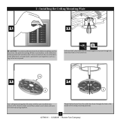
... isolators are in the middle of the ceiling mounting plate (2). 5 42798-01 • 12/28/09 • Hunter Fan Company 2 • Installing the Ceiling Mounting Plate 2.1 2.2 CAUTION: To avoid possible electrical shock, before installing your fan, disconnect the power by turning off position, securely fasten a prominent warning device, such as a tag, to the...
... isolators are in the middle of the ceiling mounting plate (2). 5 42798-01 • 12/28/09 • Hunter Fan Company 2 • Installing the Ceiling Mounting Plate 2.1 2.2 CAUTION: To avoid possible electrical shock, before installing your fan, disconnect the power by turning off position, securely fasten a prominent warning device, such as a tag, to the...
Owner's Manual
Page 10
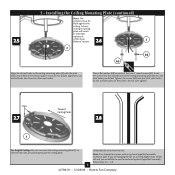
... tall and you drilled in the wood support structure. Do not over tighten. Note: Your Hunter fan comes with the pilot holes you would like to use slotted holes directly across from the fan. 2 • Installing the Ceiling Mounting Plate (continued) 2.5 Note: The isolators must be...peak. For proper alignment, use the enclosed optional pipe/ball assembly, follow Steps 3.5 - 3.9. 6 42798-01 • 12/28/09 • Hunter Fan Company Tighten the screws (65) into the slotted holes in improper operation of the two 3" wood screws (65). Insert the screws into the 9/64...
... tall and you drilled in the wood support structure. Do not over tighten. Note: Your Hunter fan comes with the pilot holes you would like to use slotted holes directly across from the fan. 2 • Installing the Ceiling Mounting Plate (continued) 2.5 Note: The isolators must be...peak. For proper alignment, use the enclosed optional pipe/ball assembly, follow Steps 3.5 - 3.9. 6 42798-01 • 12/28/09 • Hunter Fan Company Tighten the screws (65) into the slotted holes in improper operation of the two 3" wood screws (65). Insert the screws into the 9/64...
Owner's Manual
Page 11
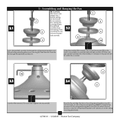
... Allen wrench (79), loosen the setscrew (8) on the ceiling mounting plate hooks. 7 42798-01 • 12/28/09 • Hunter Fan Company Note: To hang the fan, you must tilt the ceiling mounting plate cover (3) to an almost vertical position so that the ceiling mounting plate cover (3) slots sit on... the motor cover adapter to securely retighten the setscrew (8). Raise the fan and align the slots in the ceiling mounting plate cover (3) with the hooks on the ceiling mounting plate (2). 3 • Assembling and Hanging ...
... Allen wrench (79), loosen the setscrew (8) on the ceiling mounting plate hooks. 7 42798-01 • 12/28/09 • Hunter Fan Company Note: To hang the fan, you must tilt the ceiling mounting plate cover (3) to an almost vertical position so that the ceiling mounting plate cover (3) slots sit on... the motor cover adapter to securely retighten the setscrew (8). Raise the fan and align the slots in the ceiling mounting plate cover (3) with the hooks on the ceiling mounting plate (2). 3 • Assembling and Hanging ...
Owner's Manual
Page 12
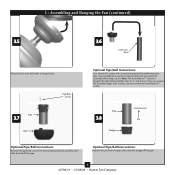
Pipe 3.7 Ball Pipe Ball Screw Optional Pipe/Ball Instructions: Your Hunter fan comes with an optional pipe/ball assembly extension pipe. If you would like to hang the fan. 3 • Assembling and Hanging the Fan (continued) 3.5 3.6 Extension Pipe Place the slots over the hooks to use a pipe/ ball assembly longer than 6 inches, do not activate... pipe Optional Pipe/Ball Instructions: Remove the pin from the pipe, then slide the wedge off the pipe. 8 42798-01 • 12/28/09 • Hunter Fan Company
Pipe 3.7 Ball Pipe Ball Screw Optional Pipe/Ball Instructions: Your Hunter fan comes with an optional pipe/ball assembly extension pipe. If you would like to hang the fan. 3 • Assembling and Hanging the Fan (continued) 3.5 3.6 Extension Pipe Place the slots over the hooks to use a pipe/ ball assembly longer than 6 inches, do not activate... pipe Optional Pipe/Ball Instructions: Remove the pin from the pipe, then slide the wedge off the pipe. 8 42798-01 • 12/28/09 • Hunter Fan Company

Owner's Manual
Page 13
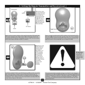
... Step 3.2. 44 •• SSeettttiinngg tthhee RReemmoottee TTrraannssmmiitttteerr aanndd RReecceeiivveerr 86 4.1 87 IMPORTANT! Screw 3.9 3 • Assembling and Hanging the Fan (continued) Ground Wire 3.10 Optional Pipe/Ball Instructions: Remove the screw and ground wire from the pipe. Go back to the transmitter. Optional... wire, wedge, pin, ball, and pipe ball screw, in the battery compartment. 9 42798-01 • 12/28/09 • Hunter Fan Company The DIP switches for the transmitter (87) are located on the flat surface of the receiver. Also, make sure the battery is ...
... Step 3.2. 44 •• SSeettttiinngg tthhee RReemmoottee TTrraannssmmiitttteerr aanndd RReecceeiivveerr 86 4.1 87 IMPORTANT! Screw 3.9 3 • Assembling and Hanging the Fan (continued) Ground Wire 3.10 Optional Pipe/Ball Instructions: Remove the screw and ground wire from the pipe. Go back to the transmitter. Optional... wire, wedge, pin, ball, and pipe ball screw, in the battery compartment. 9 42798-01 • 12/28/09 • Hunter Fan Company The DIP switches for the transmitter (87) are located on the flat surface of the receiver. Also, make sure the battery is ...
Owner's Manual
Page 14
...the toggle switch toward the side that may cause undesired operation. 42798-01 • 12/28/09 • Hunter Fan Company Clean the battery contacts and also those of the remote control transmitter. There is to remain unused for proper...) 1 = on (encendido) 4 = off (apagado) 3 = on (encendido) 2 = off (apagado) 1 = on the transmitter (87). Changes or modifications not expressly approved by Hunter Fan Company could void your local battery recycling center for an extended period of pliers or tweezers. This device must accept any interference received, including interference...
...the toggle switch toward the side that may cause undesired operation. 42798-01 • 12/28/09 • Hunter Fan Company Clean the battery contacts and also those of the remote control transmitter. There is to remain unused for proper...) 1 = on (encendido) 4 = off (apagado) 3 = on (encendido) 2 = off (apagado) 1 = on the transmitter (87). Changes or modifications not expressly approved by Hunter Fan Company could void your local battery recycling center for an extended period of pliers or tweezers. This device must accept any interference received, including interference...
Owner's Manual
Page 15
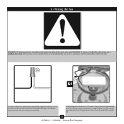
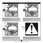
... plate and the green ground wire from the pipe/ball assembly (7). 11 42798-01 • 12/28/09 • Hunter Fan Company For all these connections use a qualified electrician. 5 • Wiring the Fan WARNING!: All wiring must be in accordance with national and local electrical codes. 70 70 5.1 To connect the wires, hold...
... plate and the green ground wire from the pipe/ball assembly (7). 11 42798-01 • 12/28/09 • Hunter Fan Company For all these connections use a qualified electrician. 5 • Wiring the Fan WARNING!: All wiring must be in accordance with national and local electrical codes. 70 70 5.1 To connect the wires, hold...
Owner's Manual
Page 16
...tag "LIVE IN") Using the small wire connectors (70), connect the wires from the fan as follows: • The white wire from the fan to the edge for the white antenna wire from the receiver (marked on white tag "FAN OUT") 5.4 WARNING! - Using the small wire connectors (70), connect the wire from... on white tag "COMMON OUT") Push all wires and wire connectors (70), except for clear reception. 12 42798-01 • 12/28/09 • Hunter Fan Company Position the receiver (86) in the ceiling mounting plate cover so that the antenna is close to the white wire from the receiver (86...
...tag "LIVE IN") Using the small wire connectors (70), connect the wires from the fan as follows: • The white wire from the fan to the edge for the white antenna wire from the receiver (marked on white tag "FAN OUT") 5.4 WARNING! - Using the small wire connectors (70), connect the wire from... on white tag "COMMON OUT") Push all wires and wire connectors (70), except for clear reception. 12 42798-01 • 12/28/09 • Hunter Fan Company Position the receiver (86) in the ceiling mounting plate cover so that the antenna is close to the white wire from the receiver (86...
Owner's Manual
Page 17
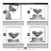
...mounting plate cover trim ring will flex out releasing the ceiling mounting plate cover trim ring (4). 13 42798-01 • 12/28/09 • Hunter Fan Company Once all three screws are in, tighten them. 3 6.3 3 6.4 4 4 Using both hands, push the ceiling mounting plate cover trim ring...turns) the three ceiling mounting plate cover screws (62) into place. 6 • Installing the Ceiling Plate Cover 2 62 6.1 3 6.2 3 Swing the fan up to remove the trim ring, press firmly on the ceiling mounting plate(2). The tabs will snap and lock into the ceiling mounting plate.
...mounting plate cover trim ring will flex out releasing the ceiling mounting plate cover trim ring (4). 13 42798-01 • 12/28/09 • Hunter Fan Company Once all three screws are in, tighten them. 3 6.3 3 6.4 4 4 Using both hands, push the ceiling mounting plate cover trim ring...turns) the three ceiling mounting plate cover screws (62) into place. 6 • Installing the Ceiling Plate Cover 2 62 6.1 3 6.2 3 Swing the fan up to remove the trim ring, press firmly on the ceiling mounting plate(2). The tabs will snap and lock into the ceiling mounting plate.
Owner's Manual
Page 18
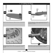
... the blade arms (44) onto the blade-to -arm screws (47) as tight as possible with a screwdriver. 14 42798-01 • 12/28/09 • Hunter Fan Company The blades may appear slightly loose after screws are holding the shipping bumpers in the blades (46). 67 7.2 46 44 Attach each blade (46...
... the blade arms (44) onto the blade-to -arm screws (47) as tight as possible with a screwdriver. 14 42798-01 • 12/28/09 • Hunter Fan Company The blades may appear slightly loose after screws are holding the shipping bumpers in the blades (46). 67 7.2 46 44 Attach each blade (46...
Owner's Manual
Page 19
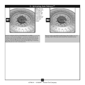
... visible through the notch in their place and continue the installation process. 15 42798-01 • 12/28/09 • Hunter Fan Company This is normal, as loose blades are a characteristic of the fan housing using a screwdriver. 8 • Activating Auto BalanceTM 8.1 Red Retaining Screws Note: After the retaining screws are using a pipe/ball...
... visible through the notch in their place and continue the installation process. 15 42798-01 • 12/28/09 • Hunter Fan Company This is normal, as loose blades are a characteristic of the fan housing using a screwdriver. 8 • Activating Auto BalanceTM 8.1 Red Retaining Screws Note: After the retaining screws are using a pipe/ball...
Owner's Manual
Page 20
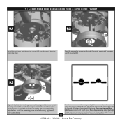
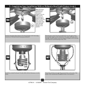
... switch housing screws (69) are firmly situated in the upper switch housing with the inner switch housing screws (69). Your Hunter fan comes with Step 9.4. 42798-01 • 12/28/09 • Hunter Fan Company If you do not want to remove it now. See Step 10.1, "Removing the Light Fixture." 16 Once you... plug connector through the center opening of the upper switch housing (30). 9.3 30 69 Align the keyhole slots in the narrow end of installing the fan with Step 9.4 now. Tighten all three screws firmly.
... switch housing screws (69) are firmly situated in the upper switch housing with the inner switch housing screws (69). Your Hunter fan comes with Step 9.4. 42798-01 • 12/28/09 • Hunter Fan Company If you do not want to remove it now. See Step 10.1, "Removing the Light Fixture." 16 Once you... plug connector through the center opening of the upper switch housing (30). 9.3 30 69 Align the keyhole slots in the narrow end of installing the fan with Step 9.4 now. Tighten all three screws firmly.
Owner's Manual
Page 21
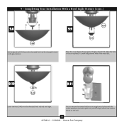
... sides of the bracket. Incorrect connection could cause improper operation and 31 damage to the product. 30 131 Connect the upper plug connector from the fan body to the upper switch housing with three outer switch housing screws (131). 9.6 9.7 259 Install the included Pin-Based CFL bulb (259), 26 Watt Maximum..., into the socket. Then, thread them . Thread the pull chains through the holes in the metal disc. 17 42798-01 • 12/28/09 • Hunter Fan Company
... sides of the bracket. Incorrect connection could cause improper operation and 31 damage to the product. 30 131 Connect the upper plug connector from the fan body to the upper switch housing with three outer switch housing screws (131). 9.6 9.7 259 Install the included Pin-Based CFL bulb (259), 26 Watt Maximum..., into the socket. Then, thread them . Thread the pull chains through the holes in the metal disc. 17 42798-01 • 12/28/09 • Hunter Fan Company
Owner's Manual
Page 22
... (150) up against the glass bowl (150). You can simply mount the remote holder on the wall. 18 42798-01 • 12/28/09 • Hunter Fan Company Or, you can mount the remote holder to any toggle switch plate with the grommet hole of the metal disc. 9.10 9.11 149 Screw...
... (150) up against the glass bowl (150). You can simply mount the remote holder on the wall. 18 42798-01 • 12/28/09 • Hunter Fan Company Or, you can mount the remote holder to any toggle switch plate with the grommet hole of the metal disc. 9.10 9.11 149 Screw...

Owner's Manual
Page 23
9 • Completing Your Installation With a Bowl Light Fixture (cont.) After your hands after installing the fan. 10 • Removing the Light Fixture 10.1 10.2 Removing the Light Fixture Disconnect the plug connectors between the two white wires. Removing the Light Fixture Remove the nut and washer from inside the center of the lower switch housing. 19 42798-01 • 12/28/09 • Hunter Fan Company Wash your installation is complete, restore power to the fan. Disconnect the plug connectors between the black wire and the black wire with a white stripe.
9 • Completing Your Installation With a Bowl Light Fixture (cont.) After your hands after installing the fan. 10 • Removing the Light Fixture 10.1 10.2 Removing the Light Fixture Disconnect the plug connectors between the two white wires. Removing the Light Fixture Remove the nut and washer from inside the center of the lower switch housing. 19 42798-01 • 12/28/09 • Hunter Fan Company Wash your installation is complete, restore power to the fan. Disconnect the plug connectors between the black wire and the black wire with a white stripe.

Owner's Manual
Page 24
... the switch housing cap and plug button to the upper switch housing with three housing assembly screws. 20 42798-01 • 12/28/09 • Hunter Fan Company Then, pull out the small (female) connector.
... the switch housing cap and plug button to the upper switch housing with three housing assembly screws. 20 42798-01 • 12/28/09 • Hunter Fan Company Then, pull out the small (female) connector.


