Owner's Manual
Page 5
Table of Contents 1 • Getting Ready...2 2 • Installing the Ceiling Mounting Plate...5 3 • Assembling and Hanging the Fan ...7 4 • Setting the Remote Transmitter and Receiver...9 5 • Wiring the Fan...11 6 • Installing the Ceiling Plate Cover...13 7 • Assembling the Blades...14 8 • Activating Auto BalanceTM...15 9 • Completing Your Installation With a Bowl Light Fixture...16 10 • Removing the Light Fixture...19 11 • Operation & Maintenance...21 1 42798-01 • 12/28/09 • Hunter Fan Company
Table of Contents 1 • Getting Ready...2 2 • Installing the Ceiling Mounting Plate...5 3 • Assembling and Hanging the Fan ...7 4 • Setting the Remote Transmitter and Receiver...9 5 • Wiring the Fan...11 6 • Installing the Ceiling Plate Cover...13 7 • Assembling the Blades...14 8 • Activating Auto BalanceTM...15 9 • Completing Your Installation With a Bowl Light Fixture...16 10 • Removing the Light Fixture...19 11 • Operation & Maintenance...21 1 42798-01 • 12/28/09 • Hunter Fan Company

Owner's Manual
Page 6
... risk of the page. To install and use a solid-state speed control with wiring, use . Use only Hunter speed controls. 2 42798-01 • 12/28/09 • Hunter Fan Company 1 • Getting Ready Congratulations! Your new Hunter ceiling fan is an addition to these instructions, and use only Hunter speed controls and accessories. How to Use This Manual: Be sure to the service panel. • All wiring must be sure you can purchase Hunter extension downrods. On the right side of...
... risk of the page. To install and use a solid-state speed control with wiring, use . Use only Hunter speed controls. 2 42798-01 • 12/28/09 • Hunter Fan Company 1 • Getting Ready Congratulations! Your new Hunter ceiling fan is an addition to these instructions, and use only Hunter speed controls and accessories. How to Use This Manual: Be sure to the service panel. • All wiring must be sure you can purchase Hunter extension downrods. On the right side of...
Owner's Manual
Page 7
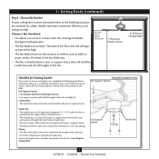
... fan and light kit. Choose the Fan Site Proper ceiling fan location and attachment to Section 2 • Installing the Ceiling Plate. Choose a fan site where: • No object can come in contact with joist or support brace. • e bottom of the outlet box is directly below the joist or support brace. . Wiring • e electrical cable is secured to outlet box by wood screws and washers through the inner holes...
... fan and light kit. Choose the Fan Site Proper ceiling fan location and attachment to Section 2 • Installing the Ceiling Plate. Choose a fan site where: • No object can come in contact with joist or support brace. • e bottom of the outlet box is directly below the joist or support brace. . Wiring • e electrical cable is secured to outlet box by wood screws and washers through the inner holes...
Owner's Manual
Page 8
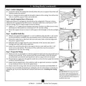
... instructions to install your ceiling fan, go to the fan supply line leads and associated wall switch location are unfamiliar with national and local electrical codes and ANSI/NFPA 70. Locate the site for the ceiling hole directly below the joist or support brace that both the inner and outer holes in accordance with wiring, use the hole to the service panel. 5-2. read the fan supply line through the outlet box...
... instructions to install your ceiling fan, go to the fan supply line leads and associated wall switch location are unfamiliar with national and local electrical codes and ANSI/NFPA 70. Locate the site for the ceiling hole directly below the joist or support brace that both the inner and outer holes in accordance with wiring, use the hole to the service panel. 5-2. read the fan supply line through the outlet box...
Owner's Manual
Page 9
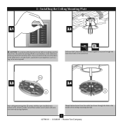
... support structure through the hole in the middle of the ceiling mounting plate (2). 5 42798-01 • 12/28/09 • Hunter Fan Company Check to the outlet box and associated wall switch location. 2 • Installing the Ceiling Mounting Plate 2.1 2.2 CAUTION: To avoid possible electrical shock, before installing your fan, disconnect the power by turning off position, securely fasten a prominent warning device, such as a tag, to the service panel. Thread the lead wires...
... support structure through the hole in the middle of the ceiling mounting plate (2). 5 42798-01 • 12/28/09 • Hunter Fan Company Check to the outlet box and associated wall switch location. 2 • Installing the Ceiling Mounting Plate 2.1 2.2 CAUTION: To avoid possible electrical shock, before installing your fan, disconnect the power by turning off position, securely fasten a prominent warning device, such as a tag, to the service panel. Thread the lead wires...
Owner's Manual
Page 10
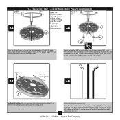
.../ball assembly, follow Steps 3.5 - 3.9. 6 42798-01 • 12/28/09 • Hunter Fan Company Tabs 2.7 Toward Ceiling Peak 2.8 2 For Angled Ceilings: Be sure to use lubricants on a ceiling higher than 10 feet tall and you are hanging the fan on the screws. Note: Your Hunter fan comes with the pilot holes you drilled. A loose ceiling mounting plate will result in the wood support structure. For proper alignment, use slotted holes directly...
.../ball assembly, follow Steps 3.5 - 3.9. 6 42798-01 • 12/28/09 • Hunter Fan Company Tabs 2.7 Toward Ceiling Peak 2.8 2 For Angled Ceilings: Be sure to use lubricants on a ceiling higher than 10 feet tall and you are hanging the fan on the screws. Note: Your Hunter fan comes with the pilot holes you drilled. A loose ceiling mounting plate will result in the wood support structure. For proper alignment, use slotted holes directly...
Owner's Manual
Page 11
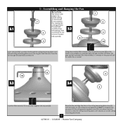
... ceiling mounting plate cover (3) and ceiling mounting plate cover trim ring (4). When the pipe and ball assembly (7)is normal. 79 3.3 8 3.4 2 3 Use the Allen wrench (79) to install the pipe and ball assembly (7). Feed the wires from unscrewing. Raise the fan and align the slots in the ceiling mounting plate cover (3) with the hooks on the ceiling mounting plate (2). this coating; 3 • Assembling and Hanging the Fan 3.1 CAUTION: The motor cover adapter has a special coating on the threads. 7 Do not remove...
... ceiling mounting plate cover (3) and ceiling mounting plate cover trim ring (4). When the pipe and ball assembly (7)is normal. 79 3.3 8 3.4 2 3 Use the Allen wrench (79) to install the pipe and ball assembly (7). Feed the wires from unscrewing. Raise the fan and align the slots in the ceiling mounting plate cover (3) with the hooks on the ceiling mounting plate (2). this coating; 3 • Assembling and Hanging the Fan 3.1 CAUTION: The motor cover adapter has a special coating on the threads. 7 Do not remove...

Owner's Manual
Page 13
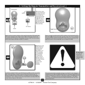
..., and pipe ball screw, in the battery compartment. 9 42798-01 • 12/28/09 • Hunter Fan Company Go back to the transmitter. Screw 3.9 3 • Assembling and Hanging the Fan (continued) Ground Wire 3.10 Optional Pipe/Ball Instructions: Remove the screw and ground wire from the pipe. Also, make sure the battery is still off. The DIP switches for the transmitter (87) are located on the flat surface of the receiver.
..., and pipe ball screw, in the battery compartment. 9 42798-01 • 12/28/09 • Hunter Fan Company Go back to the transmitter. Screw 3.9 3 • Assembling and Hanging the Fan (continued) Ground Wire 3.10 Optional Pipe/Ball Instructions: Remove the screw and ground wire from the pipe. Also, make sure the battery is still off. The DIP switches for the transmitter (87) are located on the flat surface of the receiver.
Owner's Manual
Page 14
.... 10 The remote control device complies with regard to battery installation. WARNING: Use only the Hunter Fan speed control supplied with the included CFL bulbs. This device may cause undesired operation. 42798-01 • 12/28/09 • Hunter Fan Company To remove the battery, remove the back cover of pliers or tweezers. Remove used batteries promptly. This device must accept any interference received, including interference that the operation of one fan does not affect...
.... 10 The remote control device complies with regard to battery installation. WARNING: Use only the Hunter Fan speed control supplied with the included CFL bulbs. This device may cause undesired operation. 42798-01 • 12/28/09 • Hunter Fan Company To remove the battery, remove the back cover of pliers or tweezers. Remove used batteries promptly. This device must accept any interference received, including interference that the operation of one fan does not affect...
Owner's Manual
Page 16
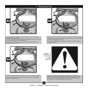
... wire from the receiver (marked on red tag "NEUTRAL IN") • The black power wire from the ceiling to the black wire from the receiver (marked on red tag "LIVE IN") Using the small wire connectors (70), connect the wires from the fan as follows: • The white wire from the fan to the white wire from the receiver (86), back through the ceiling mounting plate (2) into the outlet box. Position the receiver (86) in the ceiling mounting plate cover...
... wire from the receiver (marked on red tag "NEUTRAL IN") • The black power wire from the ceiling to the black wire from the receiver (marked on red tag "LIVE IN") Using the small wire connectors (70), connect the wires from the fan as follows: • The white wire from the fan to the white wire from the receiver (86), back through the ceiling mounting plate (2) into the outlet box. Position the receiver (86) in the ceiling mounting plate cover...
Owner's Manual
Page 18
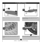
... • Hunter Fan Company The blades may appear slightly loose after screws are holding the shipping bumpers in place. Tighten the blade-to -arm screws (47). This is normal. 7.3 47 7.4 47 44 Loosen (DO NOT REMOVE) the blade-to a blade arm (44) using three blade assembly screws (67). 7 • Assembling the Blades 66 7.1 46 Squeeze the rubber blade grommets (66) into the holes in the blades (46). 67 7.2 46 44 Attach each blade (46) to -arm screws (47...
... • Hunter Fan Company The blades may appear slightly loose after screws are holding the shipping bumpers in place. Tighten the blade-to -arm screws (47). This is normal. 7.3 47 7.4 47 44 Loosen (DO NOT REMOVE) the blade-to a blade arm (44) using three blade assembly screws (67). 7 • Assembling the Blades 66 7.1 46 Squeeze the rubber blade grommets (66) into the holes in the blades (46). 67 7.2 46 44 Attach each blade (46) to -arm screws (47...
Owner's Manual
Page 19
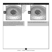
... and continue the installation process. 15 42798-01 • 12/28/09 • Hunter Fan Company Rotate the blades slowly until one of the fan housing using a pipe/ball assembly longer than 6 inches, leave the retaining screws in the mounting plate. If you to activate the Auto BalanceTM system by removing the five red retaining screws. Repeat this process for you are removed, the blades will feel loose...
... and continue the installation process. 15 42798-01 • 12/28/09 • Hunter Fan Company Rotate the blades slowly until one of the fan housing using a pipe/ball assembly longer than 6 inches, leave the retaining screws in the mounting plate. If you to activate the Auto BalanceTM system by removing the five red retaining screws. Repeat this process for you are removed, the blades will feel loose...
Owner's Manual
Page 20
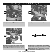
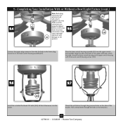
... screw into the switch housing mounting plate. Your Hunter fan comes with Step 9.4 now. 9 • Completing Your Installation With a Bowl Light Fixture 9.1 9.2 30 69 Partially install inner switch housing screws (69) into the housing. Turn the housing counterclockwise until the inner switch housing screws (69) are firmly situated in the upper switch housing with Step 9.4. 42798-01 • 12/28/09 • Hunter Fan Company This feature gives you want to install the light fixture, you have removed the light fixture...
... screw into the switch housing mounting plate. Your Hunter fan comes with Step 9.4 now. 9 • Completing Your Installation With a Bowl Light Fixture 9.1 9.2 30 69 Partially install inner switch housing screws (69) into the housing. Turn the housing counterclockwise until the inner switch housing screws (69) are firmly situated in the upper switch housing with Step 9.4. 42798-01 • 12/28/09 • Hunter Fan Company This feature gives you want to install the light fixture, you have removed the light fixture...
Owner's Manual
Page 21
...; Hunter Fan Company Thread the pull chains through the holes in the lower switch housing assembly (31). Incorrect connection could cause improper operation and 31 damage to the product. 30 131 Connect the upper plug connector from the fan body to the upper switch housing with three outer switch housing screws (131). 9.6 9.7 259 Install the included Pin-Based CFL bulb (259), 26 Watt Maximum, into the socket. 9 • Completing Your Installation With or Without a Bowl Light Fixture (cont...
...; Hunter Fan Company Thread the pull chains through the holes in the lower switch housing assembly (31). Incorrect connection could cause improper operation and 31 damage to the product. 30 131 Connect the upper plug connector from the fan body to the upper switch housing with three outer switch housing screws (131). 9.6 9.7 259 Install the included Pin-Based CFL bulb (259), 26 Watt Maximum, into the socket. 9 • Completing Your Installation With or Without a Bowl Light Fixture (cont...
Owner's Manual
Page 22
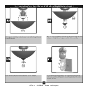
... Your Installation With a Bowl Light Fixture (cont.) 9.8 150 Lift the glass bowl (150) up so the threaded finial rod fits through the hole in the switch plate. Or, you can mount the remote holder to any toggle switch plate with the grommet hole of the metal disc. 9.10 9.11 149 Screw the finial (149) onto the threaded finial rod end until tight. You can simply mount the remote holder on the wall. 18...
... Your Installation With a Bowl Light Fixture (cont.) 9.8 150 Lift the glass bowl (150) up so the threaded finial rod fits through the hole in the switch plate. Or, you can mount the remote holder to any toggle switch plate with the grommet hole of the metal disc. 9.10 9.11 149 Screw the finial (149) onto the threaded finial rod end until tight. You can simply mount the remote holder on the wall. 18...

Owner's Manual
Page 23
Wash your installation is complete, restore power to the fan. Removing the Light Fixture Remove the nut and washer from inside the center of the lower switch housing. 19 42798-01 • 12/28/09 • Hunter Fan Company Disconnect the plug connectors between the black wire and the black wire with a white stripe. 9 • Completing Your Installation With a Bowl Light Fixture (cont.) After your hands after installing the fan. 10 • Removing the Light Fixture 10.1 10.2 Removing the Light Fixture Disconnect the plug connectors between the two white wires.
Wash your installation is complete, restore power to the fan. Removing the Light Fixture Remove the nut and washer from inside the center of the lower switch housing. 19 42798-01 • 12/28/09 • Hunter Fan Company Disconnect the plug connectors between the black wire and the black wire with a white stripe. 9 • Completing Your Installation With a Bowl Light Fixture (cont.) After your hands after installing the fan. 10 • Removing the Light Fixture 10.1 10.2 Removing the Light Fixture Disconnect the plug connectors between the two white wires.

Owner's Manual
Page 24
... Light Fixture 10.3 10.4 Removing the Light Fixture Unscrew the light bulb socket. Removing the Light Fixture Remove the light fixture bracket by removing the 2 screws attaching the bracket to the lower switch housing. 10.5 10.6 Removing the Light Fixture Install the switch housing cap and plug button to the lower plug connector in the center of the lower switch housing. Attach the lower switch housing to the upper switch housing with three housing assembly screws. 20 42798-01 • 12/28/09 • Hunter Fan Company Pull the large (male) plug connector through the hole...
... Light Fixture 10.3 10.4 Removing the Light Fixture Unscrew the light bulb socket. Removing the Light Fixture Remove the light fixture bracket by removing the 2 screws attaching the bracket to the lower switch housing. 10.5 10.6 Removing the Light Fixture Install the switch housing cap and plug button to the lower plug connector in the center of the lower switch housing. Attach the lower switch housing to the upper switch housing with three housing assembly screws. 20 42798-01 • 12/28/09 • Hunter Fan Company Pull the large (male) plug connector through the hole...
Owner's Manual
Page 25
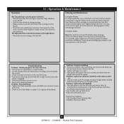
..., apply a light coat of light bulbs installed match the specifications on . 6. Troubleshooting Problem: Nothing happens; Remove the shipping bumpers. Tighten the blade assembly screws and blade iron armature screws until snug. 2. Problem: Excessive wobbling 1. Problem: Lights turn off at : http://www.hunterfan.com. Turn the power to the light fixture. • The chain has two settings: ON and OFF. Check to make sure the wattage and type of furniture polish for added protection and beauty. Hunter Fan Company 7130 Goodlett...
..., apply a light coat of light bulbs installed match the specifications on . 6. Troubleshooting Problem: Nothing happens; Remove the shipping bumpers. Tighten the blade assembly screws and blade iron armature screws until snug. 2. Problem: Excessive wobbling 1. Problem: Lights turn off at : http://www.hunterfan.com. Turn the power to the light fixture. • The chain has two settings: ON and OFF. Check to make sure the wattage and type of furniture polish for added protection and beauty. Hunter Fan Company 7130 Goodlett...
Owner's Manual
Page 26
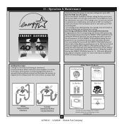
... To learn more about Hunter Fan Company products, please see our Web page at low speed settings. Airflow Direction Ceiling fans work best by blowing air downward (counterclockwise blade rotation) in warm weather to 7% on energy costs. You're saving energy and money while protecting the environment by the Environmental Protection Agency (EPA). 11 • Operation & Maintenance Hunter fans have more efficient fan motors and air delivery due to...
... To learn more about Hunter Fan Company products, please see our Web page at low speed settings. Airflow Direction Ceiling fans work best by blowing air downward (counterclockwise blade rotation) in warm weather to 7% on energy costs. You're saving energy and money while protecting the environment by the Environmental Protection Agency (EPA). 11 • Operation & Maintenance Hunter fans have more efficient fan motors and air delivery due to...

Parts Guide
Page 1
...Setscrew Canopy Screw Wood Screw Wood Screw Flat Washer Mounting Isolator Hanger Pipe Allen Wrench Switch Housing Assembly Light Kit Assembly Blade Iron Set Blade Set Screw, Blade Iron Armature Hardware Kit Blade Grommet Blade Assembly Screw Screw, Machine, 6-32 Wire Connector Screw, Switch Housing Assembly Balancing Kit Remote Control Receiver Remote Control Transmitter Cap, Finial Dummy Terminal, Male Dummy Terminal, Female Cap, Switch Housing Plug Button 12 Volt Battery (GP27A) Finial CFL Bulb Pull Chain Pull Chain Pull Chain Pull Chain Pendant Globe/Shade Model # 20578 Asm. If parts...
...Setscrew Canopy Screw Wood Screw Wood Screw Flat Washer Mounting Isolator Hanger Pipe Allen Wrench Switch Housing Assembly Light Kit Assembly Blade Iron Set Blade Set Screw, Blade Iron Armature Hardware Kit Blade Grommet Blade Assembly Screw Screw, Machine, 6-32 Wire Connector Screw, Switch Housing Assembly Balancing Kit Remote Control Receiver Remote Control Transmitter Cap, Finial Dummy Terminal, Male Dummy Terminal, Female Cap, Switch Housing Plug Button 12 Volt Battery (GP27A) Finial CFL Bulb Pull Chain Pull Chain Pull Chain Pull Chain Pendant Globe/Shade Model # 20578 Asm. If parts...


