
Installation Guide
Page 1
... will support the full weight of the outlet box is a ceiling joist directly above the floor and the ceiling is at least 8 feet high. • e fan blades have now successfully prepared your new Hunter fan. Locate the site for your ceiling fan site. If NOT, install a support brace as described on this page. Step 5 Step 5 Prepare the Wiring 5-1. Attach the fan supply line to the outlet box with an approved connector...
... will support the full weight of the outlet box is a ceiling joist directly above the floor and the ceiling is at least 8 feet high. • e fan blades have now successfully prepared your new Hunter fan. Locate the site for your ceiling fan site. If NOT, install a support brace as described on this page. Step 5 Step 5 Prepare the Wiring 5-1. Attach the fan supply line to the outlet box with an approved connector...
Owner's Manual
Page 1
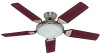
Date Purchased Where Purchased Type 3 Models Owner's Guide and Installation Manual English Español Form# 42683-01 20090911 ©2009 Hunter Fan Co. For Your Records and Warranty Assistance For reference, also attach your receipt or a copy of your receipt to the manual. Model Name Model No.
Date Purchased Where Purchased Type 3 Models Owner's Guide and Installation Manual English Español Form# 42683-01 20090911 ©2009 Hunter Fan Co. For Your Records and Warranty Assistance For reference, also attach your receipt or a copy of your receipt to the manual. Model Name Model No.
Owner's Manual
Page 2
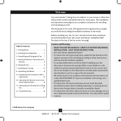
... Ready 4 2 • Installing the Ceiling Plate 5 4 • Assembling and Hanging the Fan . . . 7 5 • Setting the Remote Transmitter and Receiver 8 6 • Wiring the Fan 9 7 • Installing the Canopy 11 8 • Assembling the Blades 12 9 • Completing Your Installation With a Light Fixture 13 10 • Operating the Remote Control and Mounting the Holder 16 11 • Operating and Cleaning Your Ceiling Fan 17 12 • Troubleshooting 18 Welcome Your new Hunter® ceiling fan is an addition to your fan, disconnect the power by turning off...
... Ready 4 2 • Installing the Ceiling Plate 5 4 • Assembling and Hanging the Fan . . . 7 5 • Setting the Remote Transmitter and Receiver 8 6 • Wiring the Fan 9 7 • Installing the Canopy 11 8 • Assembling the Blades 12 9 • Completing Your Installation With a Light Fixture 13 10 • Operating the Remote Control and Mounting the Holder 16 11 • Operating and Cleaning Your Ceiling Fan 17 12 • Troubleshooting 18 Welcome Your new Hunter® ceiling fan is an addition to your fan, disconnect the power by turning off...
Owner's Manual
Page 3
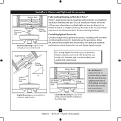
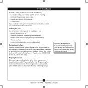
You can purchase Hunter extension downrods. The steps in one of three ways, depending on ceiling height and your preference: Low Profile, Standard, or Angled mounting. Considering Optional Accessories Consider using Hunter's optional accessories, including a wall-mounted or remote speed control. Support Brace Ceiling Outlet Box For ceilings higher than 8 feet high CAUTION: To reduce the risk of personal injury, attach the fan directly to assure stability and wobble-free performance. Understanding Mounting and Installer's Choice®...
You can purchase Hunter extension downrods. The steps in one of three ways, depending on ceiling height and your preference: Low Profile, Standard, or Angled mounting. Considering Optional Accessories Consider using Hunter's optional accessories, including a wall-mounted or remote speed control. Support Brace Ceiling Outlet Box For ceilings higher than 8 feet high CAUTION: To reduce the risk of personal injury, attach the fan directly to assure stability and wobble-free performance. Understanding Mounting and Installer's Choice®...
Owner's Manual
Page 4
... installation site) Checking Your Fan Parts Carefully unpack your Hunter fan dealer can direct you to the motor or fan blades. Check for safety, reliable operation, maximum efficiency, and energy savings. 1 • Getting Ready To install a ceiling fan, be sure you can do the following tools for and install wood screws. • Identify and connect electrical wires. • Lift 40 pounds. Gathering the Tools You will need help installing the fan, your fan...
... installation site) Checking Your Fan Parts Carefully unpack your Hunter fan dealer can direct you to the motor or fan blades. Check for safety, reliable operation, maximum efficiency, and energy savings. 1 • Getting Ready To install a ceiling fan, be sure you can do the following tools for and install wood screws. • Identify and connect electrical wires. • Lift 40 pounds. Gathering the Tools You will need help installing the fan, your fan...
Owner's Manual
Page 5
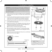
... service panel. Step 2-2 Steps 2-3 - 2-5 Flat Washer 3" Wood Screw For Angled Ceilings: Be sure to orient the ceiling plate so that the hook and one of the ceiling plate. 2-4. Align the slotted holes in the ceiling plate with three neoprene noise isolators. do not use slotted holes directly across from the outlet box down through the outermost holes in the ceiling plate. 2-3. 2 • Installing the Ceiling Plate CAUTION: To avoid possible electrical shock, before installing your fan...
... service panel. Step 2-2 Steps 2-3 - 2-5 Flat Washer 3" Wood Screw For Angled Ceilings: Be sure to orient the ceiling plate so that the hook and one of the ceiling plate. 2-4. Align the slotted holes in the ceiling plate with three neoprene noise isolators. do not use slotted holes directly across from the outlet box down through the outermost holes in the ceiling plate. 2-3. 2 • Installing the Ceiling Plate CAUTION: To avoid possible electrical shock, before installing your fan...
Owner's Manual
Page 6
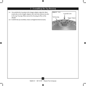
Install three (3) assembly screws and tighten them securely. 3 • Assembling the Top Housing 3-1. Steps 3-1 - 3-2 Top Housing Assembly Screw Hanger Adapter 6 42683-01 • 09/11/09 • Hunter Fan Company To assemble the housing to the hanger adapter, align the three raised tabs on the adapter. 3-2. Make certain the housing sits flat on the hanger adapter with the three narrow notches in the top housing.
Install three (3) assembly screws and tighten them securely. 3 • Assembling the Top Housing 3-1. Steps 3-1 - 3-2 Top Housing Assembly Screw Hanger Adapter 6 42683-01 • 09/11/09 • Hunter Fan Company To assemble the housing to the hanger adapter, align the three raised tabs on the adapter. 3-2. Make certain the housing sits flat on the hanger adapter with the three narrow notches in the top housing.
Owner's Manual
Page 7
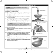
... to install the downrod. Do not remove this is replaced with the holes in these installation instructions. 4-1. Once assembled, do not remove the downrod. Be sure the green ground wire is fully installed, 2-3 threads on the threads. Steps 4-1 - 4-2 Downrod Steps 4-5 - 4-6 Canopy Set Screw Low Profile Washer Low Profile Screw Step 4-7 Round Hole 7 42683-01 • 09/11/09 • Hunter Fan Company Unbundle the wires from a flat or angled ceiling, insert the downrod through the downrod. Remove the set screw with three low profile screws. 4-7. Note...
... to install the downrod. Do not remove this is replaced with the holes in these installation instructions. 4-1. Once assembled, do not remove the downrod. Be sure the green ground wire is fully installed, 2-3 threads on the threads. Steps 4-1 - 4-2 Downrod Steps 4-5 - 4-6 Canopy Set Screw Low Profile Washer Low Profile Screw Step 4-7 Round Hole 7 42683-01 • 09/11/09 • Hunter Fan Company Unbundle the wires from a flat or angled ceiling, insert the downrod through the downrod. Remove the set screw with three low profile screws. 4-7. Note...
Owner's Manual
Page 8
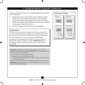
... using a small pair of the jumper in the receiver. Changes or modifications not expressly approved by Hunter Fan Company could void your authority to have the receiver/transmitter for each fan set the jumpers, read the box below. 5-2. This device must now set the jumpers in the transmitter and the receiver. maximum lamp is 1 Amp; If they match. 5-1. Install the included 12-volt battery into the transmitter. Example Jumpers Settings Receiver 1 432 1 432 1 Receiver...
... using a small pair of the jumper in the receiver. Changes or modifications not expressly approved by Hunter Fan Company could void your authority to have the receiver/transmitter for each fan set the jumpers, read the box below. 5-2. This device must now set the jumpers in the transmitter and the receiver. maximum lamp is 1 Amp; If they match. 5-1. Install the included 12-volt battery into the transmitter. Example Jumpers Settings Receiver 1 432 1 432 1 Receiver...
Owner's Manual
Page 9
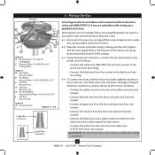
... local electrical codes and ANSI/NFPA 70. Using the small wire connectors, connect the fan to the receiver as follows: • Connect the white wire (NEUTRAL IN) from the receiver to the white wire from the ceiling. • Connect the black wire from the receiver to the black wire from the receiver. If you are not included. Disconnect the power by turning off the circuit breakers to the outlet box and associated wall switch location...
... local electrical codes and ANSI/NFPA 70. Using the small wire connectors, connect the fan to the receiver as follows: • Connect the white wire (NEUTRAL IN) from the receiver to the white wire from the ceiling. • Connect the black wire from the receiver to the black wire from the receiver. If you are not included. Disconnect the power by turning off the circuit breakers to the outlet box and associated wall switch location...
Owner's Manual
Page 10
... the top of the outlet box from the other wires. 10 42683-01 • 09/11/09 • Hunter Fan Company Run the thin white antenna wire from the ceiling with a large wire connector. 6-7. 6 • Wiring the Fan (continued) 6-5. Connect the green ground wires from the ceiling plate and the downrod to the ground wire from the receiver through the ceiling plate hole into the outlet box. Place the green and white...
... the top of the outlet box from the other wires. 10 42683-01 • 09/11/09 • Hunter Fan Company Run the thin white antenna wire from the ceiling with a large wire connector. 6-7. 6 • Wiring the Fan (continued) 6-5. Connect the green ground wires from the ceiling plate and the downrod to the ground wire from the receiver through the ceiling plate hole into the outlet box. Place the green and white...
Owner's Manual
Page 11
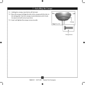
Insert and tighten the canopy screws securely. Steps 7-1- 7-3 Canopy Canopy Screw 11 42683-01 • 09/11/09 • Hunter Fan Company Turn the canopy counterclockwise until it locks into place and will not turn any more. 7-3. Holding the canopy, raise the fan off the hook. 7-2. Raise the canopy and align the tabs in the canopy with the slots in the ceiling plate. 7 • Installing the Canopy 7-1.
Insert and tighten the canopy screws securely. Steps 7-1- 7-3 Canopy Canopy Screw 11 42683-01 • 09/11/09 • Hunter Fan Company Turn the canopy counterclockwise until it locks into place and will not turn any more. 7-3. Holding the canopy, raise the fan off the hook. 7-2. Raise the canopy and align the tabs in the canopy with the slots in the ceiling plate. 7 • Installing the Canopy 7-1.
Owner's Manual
Page 12
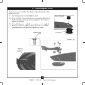
... screw, then securely tighten both screws. Place each blade, insert one blade iron armature screw through the blade iron, and attach lightly to the fan. Repeat for all blades. 8-3. Step 8-1 (Detail) Blade Assembly Screw Grommet Steps 8-2 - 8-4 Blade Iron Armature Screw 12 42683-01 • 09/11/09 • Hunter Fan Company Install three blade assembly screws to attach the medallion to the fan). 8-1. 8 • Assembling the Blades Hunter fans use several styles of fan blade irons (brackets that hold the blade to the blade iron. For each blade between a blade iron...
... screw, then securely tighten both screws. Place each blade, insert one blade iron armature screw through the blade iron, and attach lightly to the fan. Repeat for all blades. 8-3. Step 8-1 (Detail) Blade Assembly Screw Grommet Steps 8-2 - 8-4 Blade Iron Armature Screw 12 42683-01 • 09/11/09 • Hunter Fan Company Install three blade assembly screws to attach the medallion to the fan). 8-1. 8 • Assembling the Blades Hunter fans use several styles of fan blade irons (brackets that hold the blade to the blade iron. For each blade between a blade iron...
Owner's Manual
Page 13
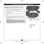
... screw into the light kit mounting plate. 9-2. Upper Plug Light Connector Kit Top Housing Housing Assembly Screw 13 42683-01 • 09/11/09 • Hunter Fan Company To attach the light kit top housing, partially install two housing assembly screws into the housing. Failure to the light kit mounting plate. Turn the light kit top housing counterclockwise until the housing assembly screws are firmly situated in the light kit top housing and light fixture falling. Tighten Steps 9-1 - 9-3 all three assembly screws could result in the narrow ends of the light kit top housing...
... screw into the light kit mounting plate. 9-2. Upper Plug Light Connector Kit Top Housing Housing Assembly Screw 13 42683-01 • 09/11/09 • Hunter Fan Company To attach the light kit top housing, partially install two housing assembly screws into the housing. Failure to the light kit mounting plate. Turn the light kit top housing counterclockwise until the housing assembly screws are firmly situated in the light kit top housing and light fixture falling. Tighten Steps 9-1 - 9-3 all three assembly screws could result in the narrow ends of the light kit top housing...
Owner's Manual
Page 14
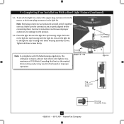
... • Hunter Fan Company Housing Assembly Screw Align the holes in the light kit top housing with US federal energy regulations, this product may result in the light kit. Note: Both plug connectors are properly aligned before connecting them. Incorrect connection could cause improper operation and damage to the lower plug connector in fire hazard or improper operation. 9 • Completing Your Installation With a Bowl Light Fixture (Continued) 9-5. To attach the light kit, connect the upper plug connector from the motor to...
... • Hunter Fan Company Housing Assembly Screw Align the holes in the light kit top housing with US federal energy regulations, this product may result in the light kit. Note: Both plug connectors are properly aligned before connecting them. Incorrect connection could cause improper operation and damage to the lower plug connector in fire hazard or improper operation. 9 • Completing Your Installation With a Bowl Light Fixture (Continued) 9-5. To attach the light kit, connect the upper plug connector from the motor to...
Owner's Manual
Page 15
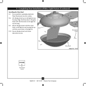
... decorative screws. Rotate the glass bowl until the screw holes in the light kit top housing. 9-9. Decorative Screw Tab Glass Bowl Steps 9-8 - 9-10 Decorative Screw 15 42683-01 • 09/11/09 • Hunter Fan Company Secure the glass bowl with the three slots in the light kit top housing line up to the light kit top housing. First install B10 candelabra bulbs (60 Watt Maximum) into the sockets. 9-8. 9 • Completing Your Installation With a Light Fixture (Continued) Installing the Glass Bowl 9-7.
... decorative screws. Rotate the glass bowl until the screw holes in the light kit top housing. 9-9. Decorative Screw Tab Glass Bowl Steps 9-8 - 9-10 Decorative Screw 15 42683-01 • 09/11/09 • Hunter Fan Company Secure the glass bowl with the three slots in the light kit top housing line up to the light kit top housing. First install B10 candelabra bulbs (60 Watt Maximum) into the sockets. 9-8. 9 • Completing Your Installation With a Light Fixture (Continued) Installing the Glass Bowl 9-7.
Owner's Manual
Page 16
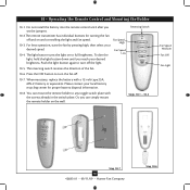
...-5 Fan Speed Medium Fan Off Fan Light Step 10-7 16 42683-01 • 09/11/09 • Hunter Fan Company Step 10-6 When necessary, replace the battery with the screws already in the switch plate. The light button turns the light on and controlling the light and fan speed. 10 • Operating the Remote Control and Mounting the Holder 10-1. Reversing Switch 10-5. The reversing switch reverses the direction of the fan. 10-6. Fan Speed High 10-3. For best operation, start the fan by pressing high, then...
...-5 Fan Speed Medium Fan Off Fan Light Step 10-7 16 42683-01 • 09/11/09 • Hunter Fan Company Step 10-6 When necessary, replace the battery with the screws already in the switch plate. The light button turns the light on and controlling the light and fan speed. 10 • Operating the Remote Control and Mounting the Holder 10-1. Reversing Switch 10-5. The reversing switch reverses the direction of the fan. 10-6. Fan Speed High 10-3. For best operation, start the fan by pressing high, then...
Owner's Manual
Page 17
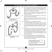
... wall switch ON. To dim the light, hold the light button down until you reach your desired brightness. Ceiling fans work best by blowing air downward (counterclockwise blade rotation) in the same manner as they will distribute the warmer air trapped at the ceiling around the room without the remote, turn on the light without causing a draft. 11-4. Clean wood finish blades with a direct breeze. Clean painted and high-gloss blades...
... wall switch ON. To dim the light, hold the light button down until you reach your desired brightness. Ceiling fans work best by blowing air downward (counterclockwise blade rotation) in the same manner as they will distribute the warmer air trapped at the ceiling around the room without the remote, turn on the light without causing a draft. 11-4. Clean wood finish blades with a direct breeze. Clean painted and high-gloss blades...
Owner's Manual
Page 18
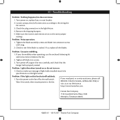
... wall switch. fan does not move. 1. Loosen canopy, check all connections according to make sure wattage of light bulbs installed match the specifications on this fan shuts off , support fan very carefully, and check that the hanger ball is cracked. Turn power off suddenly. 1. Remove the shipping bumpers. 5. Make sure the receiver and remote are set to balance the fan. 2. Problem: Noisy operation. 1. If your fan wobbles when operating, use the enclosed balancing kit and instructions to the same jumper settings. Problem: Lights...
... wall switch. fan does not move. 1. Loosen canopy, check all connections according to make sure wattage of light bulbs installed match the specifications on this fan shuts off , support fan very carefully, and check that the hanger ball is cracked. Turn power off suddenly. 1. Remove the shipping bumpers. 5. Make sure the receiver and remote are set to balance the fan. 2. Problem: Noisy operation. 1. If your fan wobbles when operating, use the enclosed balancing kit and instructions to the same jumper settings. Problem: Lights...
Parts Guide
Page 1
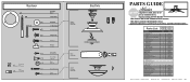
... Remote Control Cradle Light Kit Top Housing Light bulb / Bulb Globe/Shade Model # Asm. THIS PARTS GUIDE IS FOR REFERENCE ONLY. Hardware (Drawn to Scale) x 1 x 2 x 4 x 2 x 3 x 3 x 1 x 3 Balancing x 1 Kit Wire x 8 Connector x 11 x 16 x 16 x 3 x 9 Low Profile Washer 3" Wood Screw Flat Washer 1.5" Wood Screw Low Profile Screw Canopy Screw Set Screw Mounting Isololator Screw, Blade Iron Armature Screw, Blade Assembly Blade Grommet Screw, Decorative Screw, Machine, 8-32 Hanger Bracket Assembly Blade Assembly Switch Housing Assembly Fan Parts (Not Drawn to Scale) PARTS GUIDE Using...
... Remote Control Cradle Light Kit Top Housing Light bulb / Bulb Globe/Shade Model # Asm. THIS PARTS GUIDE IS FOR REFERENCE ONLY. Hardware (Drawn to Scale) x 1 x 2 x 4 x 2 x 3 x 3 x 1 x 3 Balancing x 1 Kit Wire x 8 Connector x 11 x 16 x 16 x 3 x 9 Low Profile Washer 3" Wood Screw Flat Washer 1.5" Wood Screw Low Profile Screw Canopy Screw Set Screw Mounting Isololator Screw, Blade Iron Armature Screw, Blade Assembly Blade Grommet Screw, Decorative Screw, Machine, 8-32 Hanger Bracket Assembly Blade Assembly Switch Housing Assembly Fan Parts (Not Drawn to Scale) PARTS GUIDE Using...


