Installation Instructions
Page 2
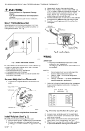
... wallplate over the wall anchors. 6. Select Thermostat Location Select a location for specific equipment applications. 1. Select thermostat location. Hot or cold air from thermostat. Terminal identifications for the application. 3. See Fig. 5. 5. TB7100A1000 MULTIPRO™ MULTISPEED AND MULTIPURPOSE THERMOSTAT CAUTION Electrical Shock or Equipment Damage Hazard. See Fig. 1. 3. NOTES: - - - Push excess wire back into the drilled holes until flush...
... wallplate over the wall anchors. 6. Select Thermostat Location Select a location for specific equipment applications. 1. Select thermostat location. Hot or cold air from thermostat. Terminal identifications for the application. 3. See Fig. 5. 5. TB7100A1000 MULTIPRO™ MULTISPEED AND MULTIPURPOSE THERMOSTAT CAUTION Electrical Shock or Equipment Damage Hazard. See Fig. 1. 3. NOTES: - - - Push excess wire back into the drilled holes until flush...
Installation Instructions
Page 3
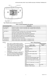
...Coil (with batteries. Medium fan speed for Fan Coil and PTAC applications. Common wire is optional when thermostat is configured for a heat pump in place between RC and R. If thermostat is used with Auxiliary Heat) 14 2 Pipe Fan Coil (no Auxiliary Heat...wires to heat pump, PTAC. Terminal Designation Description RC (see Note 4) Indoor remote sensor, remote setback, or changeover input. S1 (see Note 1) Power for cool (O-factory setting) or heat (B). High fan speed for Fan Coil applications only. WIRE TB7100A1000 MULTIPRO™ MULTISPEED AND MULTIPURPOSE THERMOSTAT...
...Coil (with batteries. Medium fan speed for Fan Coil and PTAC applications. Common wire is optional when thermostat is configured for a heat pump in place between RC and R. If thermostat is used with Auxiliary Heat) 14 2 Pipe Fan Coil (no Auxiliary Heat...wires to heat pump, PTAC. Terminal Designation Description RC (see Note 4) Indoor remote sensor, remote setback, or changeover input. S1 (see Note 1) Power for cool (O-factory setting) or heat (B). High fan speed for Fan Coil applications only. WIRE TB7100A1000 MULTIPRO™ MULTISPEED AND MULTIPURPOSE THERMOSTAT...
Installation Instructions
Page 4
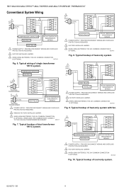
... 3 C W1 G G2 Y G3 24 VAC O/B S1 L2 RC S2 R2 COMPRESSOR CONTACTOR FAN RELAY INDOOR TEMPERATURE SENSOR/REMOTE SETBACK 1 POWER SUPPLY. TB7100A1000 MULTIPRO™ MULTISPEED AND MULTIPURPOSE THERMOSTAT Conventional System Wiring L1 1 (HOT) C 3 W1 G G2 Y G3 24 VAC O/B S1 L2 RC S2 R2 COMPRESSOR CONTACTOR FAN RELAY INDOOR TEMPERATURE SENSOR/REMOTE SETBACK.... 1 L1 (HOT) C 3 W1 G G2 L2 24 VAC Y G3 O/B S1 RC S2 R2 HEAT RELAY INDOOR TEMPERATURE SENSOR/REMOTE SETBACK 1 POWER SUPPLY. Typical wiring of single transformer 1H/1C system.
... 3 C W1 G G2 Y G3 24 VAC O/B S1 L2 RC S2 R2 COMPRESSOR CONTACTOR FAN RELAY INDOOR TEMPERATURE SENSOR/REMOTE SETBACK 1 POWER SUPPLY. TB7100A1000 MULTIPRO™ MULTISPEED AND MULTIPURPOSE THERMOSTAT Conventional System Wiring L1 1 (HOT) C 3 W1 G G2 Y G3 24 VAC O/B S1 L2 RC S2 R2 COMPRESSOR CONTACTOR FAN RELAY INDOOR TEMPERATURE SENSOR/REMOTE SETBACK.... 1 L1 (HOT) C 3 W1 G G2 L2 24 VAC Y G3 O/B S1 RC S2 R2 HEAT RELAY INDOOR TEMPERATURE SENSOR/REMOTE SETBACK 1 POWER SUPPLY. Typical wiring of single transformer 1H/1C system.
Installation Instructions
Page 5
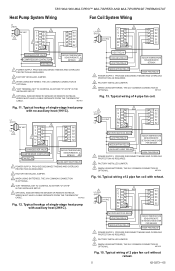
...TO CONTROL AS EITHER "O" OR "B" IN THE INSTALLER SETUP. 5 OPTIONAL INDOOR REMOTE SENSOR OR REMOTE SETBACK. WIRES MUST HAVE A CABLE SEPARATE FROM THE THERMOSTAT CABLE. M27423 Fig. 13. PROVIDE DISCONNECT MEANS AND OVERLOAD PROTECTION AS REQUIRED. 2 FACTORY INSTALLED JUMPER. 3 ...CHANGEOVER VALVE COMPRESSOR CONTACTOR FAN RELAY INDOOR TEMPERATURE SENSOR/REMOTE SETBACK 5 AUXILIARY HEAT RELAY 1 POWER SUPPLY. TB7100A1000 MULTIPRO™ MULTISPEED AND MULTIPURPOSE THERMOSTAT Heat Pump System Wiring Fan Coil System Wiring L1 (HOT) 3 24 VAC C W1 L2 G G2 1 Y G3 4 O/B S1 RC ...
...TO CONTROL AS EITHER "O" OR "B" IN THE INSTALLER SETUP. 5 OPTIONAL INDOOR REMOTE SENSOR OR REMOTE SETBACK. WIRES MUST HAVE A CABLE SEPARATE FROM THE THERMOSTAT CABLE. M27423 Fig. 13. PROVIDE DISCONNECT MEANS AND OVERLOAD PROTECTION AS REQUIRED. 2 FACTORY INSTALLED JUMPER. 3 ...CHANGEOVER VALVE COMPRESSOR CONTACTOR FAN RELAY INDOOR TEMPERATURE SENSOR/REMOTE SETBACK 5 AUXILIARY HEAT RELAY 1 POWER SUPPLY. TB7100A1000 MULTIPRO™ MULTISPEED AND MULTIPURPOSE THERMOSTAT Heat Pump System Wiring Fan Coil System Wiring L1 (HOT) 3 24 VAC C W1 L2 G G2 1 Y G3 4 O/B S1 RC ...
Installation Instructions
Page 6
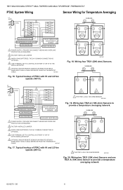
TB7100A1000 MULTIPRO™ MULTISPEED AND MULTIPURPOSE THERMOSTAT PTAC System Wiring Sensor Wiring for Temperature Averaging L1 (HOT) 3 24 VAC C W1 L2 G G2 1 Y G3 4 O/B S1 RC S2 R2 CHANGEOVER VALVE COMPRESSOR CONTACTOR LOW FAN RELAY INDOOR TEMPERATURE SENSOR/REMOTE SETBACK 5 HIGH FAN RELAY 1 POWER SUPPLY. WIRES MUST HAVE A CABLE SEPARATE FROM THE THERMOSTAT CABLE. Wiring... THE INSTALLER SETUP. 5 OPTIONAL INDOOR REMOTE SENSOR OR REMOTE SETBACK. WIRES MUST HAVE A CABLE SEPARATE FROM THE THERMOSTAT CABLE. SUBBASE S1 S2 TR21 TR21 T T T T TR21 TR21...
TB7100A1000 MULTIPRO™ MULTISPEED AND MULTIPURPOSE THERMOSTAT PTAC System Wiring Sensor Wiring for Temperature Averaging L1 (HOT) 3 24 VAC C W1 L2 G G2 1 Y G3 4 O/B S1 RC S2 R2 CHANGEOVER VALVE COMPRESSOR CONTACTOR LOW FAN RELAY INDOOR TEMPERATURE SENSOR/REMOTE SETBACK 5 HIGH FAN RELAY 1 POWER SUPPLY. WIRES MUST HAVE A CABLE SEPARATE FROM THE THERMOSTAT CABLE. Wiring... THE INSTALLER SETUP. 5 OPTIONAL INDOOR REMOTE SENSOR OR REMOTE SETBACK. WIRES MUST HAVE A CABLE SEPARATE FROM THE THERMOSTAT CABLE. SUBBASE S1 S2 TR21 TR21 T T T T TR21 TR21...
Installation Instructions
Page 7
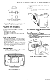
... THE THERMOSTAT CABLE. Wiring four C7189U (10K ohm) Sensors to Wallplate 1. M22260 Fig. 23. Install two AA alkaline batteries on the back of the thermostat wallplate. Mount thermostat to set the real-time clock. WALL Installing Batteries 1. Align the terminal screw blocks with battery backup (AA alkaline). M22259 7 62-0273-05 Installing batteries. TB7100A1000 MULTIPRO™...
... THE THERMOSTAT CABLE. Wiring four C7189U (10K ohm) Sensors to Wallplate 1. M22260 Fig. 23. Install two AA alkaline batteries on the back of the thermostat wallplate. Mount thermostat to set the real-time clock. WALL Installing Batteries 1. Align the terminal screw blocks with battery backup (AA alkaline). M22259 7 62-0273-05 Installing batteries. TB7100A1000 MULTIPRO™...
Installation Instructions
Page 14
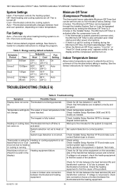
... present, check wire connection (loose or broken) between the thermostat and the heating equipment. 62-0273-05 14 TROUBLESHOOTING (TABLE 6) Table 6. System type Selection is not present, check the heating equipment to find the cause of the transformer between thermostat and heating equipment. TB7100A1000 MULTIPRO™ MULTISPEED AND MULTIPURPOSE THERMOSTAT System Settings Heat-Thermostat controls the heating...
... present, check wire connection (loose or broken) between the thermostat and the heating equipment. 62-0273-05 14 TROUBLESHOOTING (TABLE 6) Table 6. System type Selection is not present, check the heating equipment to find the cause of the transformer between thermostat and heating equipment. TB7100A1000 MULTIPRO™ MULTISPEED AND MULTIPURPOSE THERMOSTAT System Settings Heat-Thermostat controls the heating...
Installation Instructions
Page 15
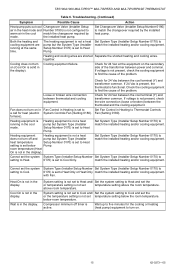
... Changeover Valve (Installer Setup Number 0190) to Heat Pump. Heating and cooling wires are running in Heating to Cool Only. If voltage is not configured to find the cause of the transformer between thermostat and cooling equipment. TB7100A1000 MULTIPRO™ MULTISPEED AND MULTIPURPOSE THERMOSTAT Table 6. Troubleshooting. (Continued) Symptom Possible Cause Action Heat pump puts out...
... Changeover Valve (Installer Setup Number 0190) to Heat Pump. Heating and cooling wires are running in Heating to Cool Only. If voltage is not configured to find the cause of the transformer between thermostat and cooling equipment. TB7100A1000 MULTIPRO™ MULTISPEED AND MULTIPURPOSE THERMOSTAT Table 6. Troubleshooting. (Continued) Symptom Possible Cause Action Heat pump puts out...


