Installation Instructions
Page 1
...them could damage the product or cause a hazardous condition. 2. T8400C, T8401C Electronic Thermostats INSTALLATION INSTRUCTIONS The T8400C and T8401C Thermostats provide singlestage, non-programmable temperature control for 24V heating-cooling systems with the screws provided (see Wiring section. ® U.S. ...The thermostat functions normally even when not level. Heating cycle rate is suitable for appearance. After wiring the wallplate, plug the hole to Wall IMPORTANT Level only for your old control in corners. - Registered Trademark Copyright © 2004 Honeywell ...
...them could damage the product or cause a hazardous condition. 2. T8400C, T8401C Electronic Thermostats INSTALLATION INSTRUCTIONS The T8400C and T8401C Thermostats provide singlestage, non-programmable temperature control for 24V heating-cooling systems with the screws provided (see Wiring section. ® U.S. ...The thermostat functions normally even when not level. Heating cycle rate is suitable for appearance. After wiring the wallplate, plug the hole to Wall IMPORTANT Level only for your old control in corners. - Registered Trademark Copyright © 2004 Honeywell ...
Installation Instructions
Page 2
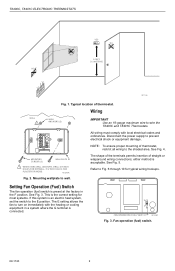
...M12580 Fig. 3. T8400C, T8401C ELECTRONIC THERMOSTATS YES NO NO 5 FEET [1.5 METERS] NO M11338 Fig. 1. All wiring must comply with the heating or cooling equipment in the F position. See Fig. 4. M12202A Fig. 2. See Fig. 5. The shape of the terminals permits insertion of thermostat. Refer to the E position.... This is the correct setting for most systems. If this system is an electric heat system, set the switch to Fig. 6 through 10 for typical wiring hookups....
...M12580 Fig. 3. T8400C, T8401C ELECTRONIC THERMOSTATS YES NO NO 5 FEET [1.5 METERS] NO M11338 Fig. 1. All wiring must comply with the heating or cooling equipment in the F position. See Fig. 4. M12202A Fig. 2. See Fig. 5. The shape of the terminals permits insertion of thermostat. Refer to the E position.... This is the correct setting for most systems. If this system is an electric heat system, set the switch to Fig. 6 through 10 for typical wiring hookups....
Installation Instructions
Page 3
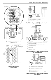
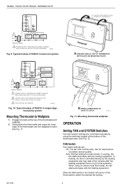
... W Y B O M13274 Fig. 5. PROVIDE DISCONNECT MEANS AND OVERLOAD PROTECTION AS REQUIRED. 2 CAN BE USED FOR CHANGEOVER VALVE ON SINGLE-STAGE HEAT PUMP SYSTEMS. 3 FACTORY INSTALLED JUMPER. 4 FIELD INSTALLED JUMPER. M13275 Fig. 6. Restrict wiring to shaded area (T8400C shown). PROVIDE DISCONNECT MEANS ...SYSTEM SWITCH IS IN THE OFF POSITION. Typical hookup of T8400C in heat-cool system with single transformer. PROVIDE DISCONNECT MEANS AND OVERLOAD PROTECTION AS REQUIRED. 2 FACTORY INSTALLED JUMPER. T8400C, T8401C ELECTRONIC THERMOSTATS KEEP WIRING IN SHADED AREA G Rc R W B Y O MOUNTING...
... W Y B O M13274 Fig. 5. PROVIDE DISCONNECT MEANS AND OVERLOAD PROTECTION AS REQUIRED. 2 CAN BE USED FOR CHANGEOVER VALVE ON SINGLE-STAGE HEAT PUMP SYSTEMS. 3 FACTORY INSTALLED JUMPER. 4 FIELD INSTALLED JUMPER. M13275 Fig. 6. Restrict wiring to shaded area (T8400C shown). PROVIDE DISCONNECT MEANS ...SYSTEM SWITCH IS IN THE OFF POSITION. Typical hookup of T8400C in heat-cool system with single transformer. PROVIDE DISCONNECT MEANS AND OVERLOAD PROTECTION AS REQUIRED. 2 FACTORY INSTALLED JUMPER. T8400C, T8401C ELECTRONIC THERMOSTATS KEEP WIRING IN SHADED AREA G Rc R W B Y O MOUNTING...
Installation Instructions
Page 4
... CooSlYOSfTf EHMeat B PRESS LOWER EDGE OF CASE TO LATCH. DASHED LINES INDICATE TABS ON BACK OF THERMOSTAT Set Room AuFtoANOn CoSoYl SOTffEMHeat A ENGAGE TABS AT TOP OF THERMOSTAT WITH SLOTS ON MOUNTING PLATE. T8400C, T8401C ELECTRONIC THERMOSTATS G C R W B Y O 1 L1 (HOT) 24V L2 TRANSFORMER HEAT RELAY COOL RELAY FAN RELAY 1 POWER SUPPLY. Slide the FAN switch in...
... CooSlYOSfTf EHMeat B PRESS LOWER EDGE OF CASE TO LATCH. DASHED LINES INDICATE TABS ON BACK OF THERMOSTAT Set Room AuFtoANOn CoSoYl SOTffEMHeat A ENGAGE TABS AT TOP OF THERMOSTAT WITH SLOTS ON MOUNTING PLATE. T8400C, T8401C ELECTRONIC THERMOSTATS G C R W B Y O 1 L1 (HOT) 24V L2 TRANSFORMER HEAT RELAY COOL RELAY FAN RELAY 1 POWER SUPPLY. Slide the FAN switch in...
Installation Instructions
Page 5
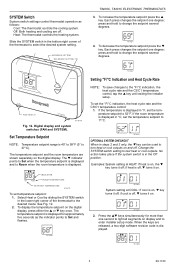
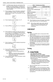
... If the temperature is 40° to 99°F (5° to test heat or cool outputs. M14683 OPTIONAL SYSTEM CHECKOUT When in the lower right corner of the thermostat to select the desired system setting. Press the ▲▼ keys simultaneously for...room temperature is displayed in the Off position. If the room temperature is displayed. . Heat: The thermostat controls the heating system. INCREASE SETTING DECREASE SETTING T8400C, T8401C ELECTRONIC THERMOSTATS 3. To display the temperature setpoint on display and to enter installer setup mode. if cool...
... If the temperature is 40° to 99°F (5° to test heat or cool outputs. M14683 OPTIONAL SYSTEM CHECKOUT When in the lower right corner of the thermostat to select the desired system setting. Press the ▲▼ keys simultaneously for...room temperature is displayed in the Off position. If the room temperature is displayed. . Heat: The thermostat controls the heating system. INCREASE SETTING DECREASE SETTING T8400C, T8401C ELECTRONIC THERMOSTATS 3. To display the temperature setpoint on display and to enter installer setup mode. if cool...
Installation Instructions
Page 6
...ELECTRONIC THERMOSTATS NOTE: In installer setup mode only, each press of the ▼ key momentarily displays 02. Each press of the ▲ key momentarily displays 01. A typical example is shown, but information displayed varies by model) is shown. M14687 4. Press the ▼ key to equipment manufacturer's instructions. 10. bRefer to change the heat...Table 1 for factory use of an outdoor temperature may cause compressor damage. When using an electric heat thermostat, the fan starts immediately. 3. Press the ▲ key. Press the ▼ key to display °C or °F. ...
...ELECTRONIC THERMOSTATS NOTE: In installer setup mode only, each press of the ▼ key momentarily displays 02. Each press of the ▲ key momentarily displays 01. A typical example is shown, but information displayed varies by model) is shown. M14687 4. Press the ▼ key to equipment manufacturer's instructions. 10. bRefer to change the heat...Table 1 for factory use of an outdoor temperature may cause compressor damage. When using an electric heat thermostat, the fan starts immediately. 3. Press the ▲ key. Press the ▼ key to display °C or °F. ...
Installation Instructions
Page 7
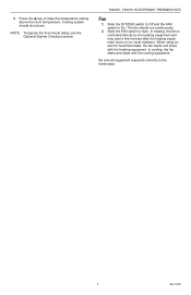
...Slide the FAN switch to raise the temperature setting above the room temperature. 3. The fan should shut down. When using an electric heat thermostat, the fan starts and stops with the cooling equipment. Press the ▲ key to Auto. In cooling, the fan starts and stops... with the heating equipment. In heating, the fan is controlled directly by the heating equipment and may start a few minutes after the heating equipment turns on (on most systems). Slide the SYSTEM switch to Off and the FAN switch to the thermostat. 7 69-1740 T8400C, T8401C ELECTRONIC THERMOSTATS Fan 1. Be ...
...Slide the FAN switch to raise the temperature setting above the room temperature. 3. The fan should shut down. When using an electric heat thermostat, the fan starts and stops with the cooling equipment. Press the ▲ key to Auto. In cooling, the fan starts and stops... with the heating equipment. In heating, the fan is controlled directly by the heating equipment and may start a few minutes after the heating equipment turns on (on most systems). Slide the SYSTEM switch to Off and the FAN switch to the thermostat. 7 69-1740 T8400C, T8401C ELECTRONIC THERMOSTATS Fan 1. Be ...


