Installation Instructions
Page 1
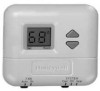
... Electronic Thermostats INSTALLATION INSTRUCTIONS The T8400C and T8401C Thermostats provide singlestage, non-programmable temperature control for 24V heating-cooling systems with manual changeover from heat to make sure the product is a precision instrument and was carefully adjusted at the factory. Handle it can be a trained, experienced service technician. 4. The thermostat functions normally even when not level. After installation is powered through the entrance hole on the wall. 2. Cooling cycle rate is replacing a control that...
... Electronic Thermostats INSTALLATION INSTRUCTIONS The T8400C and T8401C Thermostats provide singlestage, non-programmable temperature control for 24V heating-cooling systems with manual changeover from heat to make sure the product is a precision instrument and was carefully adjusted at the factory. Handle it can be a trained, experienced service technician. 4. The thermostat functions normally even when not level. After installation is powered through the entrance hole on the wall. 2. Cooling cycle rate is replacing a control that...
Installation Instructions
Page 2
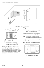
... cooling equipment in the F position. MOUNTING SCREWS (2) WALLPLATE 1 WHEN USING WALL ANCHORS, DRILL 3/16 INCH HOLES FOR DRYWALL, 7/32 INCH HOLES FOR PLASTER OR WOOD. Mounting wallplate to wire the T8400C and T8401C Thermostats. Refer to prevent electrical shock or equipment damage. This is the correct setting for typical wiring hookups. E F FAN OPERATION (FUEL) SWITCH M12580 Fig. 3. See Fig. 3. T8400C, T8401C ELECTRONIC THERMOSTATS...
... cooling equipment in the F position. MOUNTING SCREWS (2) WALLPLATE 1 WHEN USING WALL ANCHORS, DRILL 3/16 INCH HOLES FOR DRYWALL, 7/32 INCH HOLES FOR PLASTER OR WOOD. Mounting wallplate to wire the T8400C and T8401C Thermostats. Refer to prevent electrical shock or equipment damage. This is the correct setting for typical wiring hookups. E F FAN OPERATION (FUEL) SWITCH M12580 Fig. 3. See Fig. 3. T8400C, T8401C ELECTRONIC THERMOSTATS...
Installation Instructions
Page 3
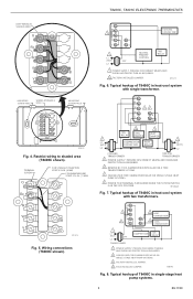
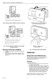
... Fig. 6. G Rc 3 R W 4 Y 2 HEAT CHANGEOVER B 2 COOL O CHANGEOVER 1 L1 (HOT) 24V L2 TRANSFORMER COMPRESSOR FAN RELAY 1 POWER SUPPLY. G Rc 2 R W B Y O COOLING CONTACTOR 1 L1 (HOT) 24V L2 HEATING PRIMARY CONTROL FAN RELAY 1 POWER SUPPLY. PROVIDE DISCONNECT MEANS AND OVERLOAD PROTECTION AS REQUIRED. 2 REMOVE RC TO R JUMPER WHEN INSTALLED ON A TWO TRANSFORMER SYSTEM. 3 CAN BE USED FOR CHANGEOVER VALVE ON SINGLE-STAGE HEAT PUMP SYSTEMS. 4 POWER TO R TERMINAL IS REQUIRED WHEN THE SYSTEM SWITCH IS IN...
... Fig. 6. G Rc 3 R W 4 Y 2 HEAT CHANGEOVER B 2 COOL O CHANGEOVER 1 L1 (HOT) 24V L2 TRANSFORMER COMPRESSOR FAN RELAY 1 POWER SUPPLY. G Rc 2 R W B Y O COOLING CONTACTOR 1 L1 (HOT) 24V L2 HEATING PRIMARY CONTROL FAN RELAY 1 POWER SUPPLY. PROVIDE DISCONNECT MEANS AND OVERLOAD PROTECTION AS REQUIRED. 2 REMOVE RC TO R JUMPER WHEN INSTALLED ON A TWO TRANSFORMER SYSTEM. 3 CAN BE USED FOR CHANGEOVER VALVE ON SINGLE-STAGE HEAT PUMP SYSTEMS. 4 POWER TO R TERMINAL IS REQUIRED WHEN THE SYSTEM SWITCH IS IN...
Installation Instructions
Page 4
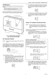
... thermostat wallplate. FAN Switch Fan switch settings are controlled manually by the heating equipment and may start a few minutes after the heating equipment turns on (on most homes. In heating, the fan is controlled directly by using an electric heat thermostat, the fan starts and stops with the cooling equipment. DASHED LINES INDICATE TABS ON BACK OF THERMOSTAT Set Room AuFtoANOn CoSoYl SOTffEMHeat A ENGAGE TABS AT TOP OF THERMOSTAT WITH SLOTS ON MOUNTING PLATE. Swing down the thermostat...
... thermostat wallplate. FAN Switch Fan switch settings are controlled manually by the heating equipment and may start a few minutes after the heating equipment turns on (on most homes. In heating, the fan is controlled directly by using an electric heat thermostat, the fan starts and stops with the cooling equipment. DASHED LINES INDICATE TABS ON BACK OF THERMOSTAT Set Room AuFtoANOn CoSoYl SOTffEMHeat A ENGAGE TABS AT TOP OF THERMOSTAT WITH SLOTS ON MOUNTING PLATE. Swing down the thermostat...
Installation Instructions
Page 5
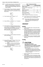
... as follows: Cool: The thermostat controls the cooling system. SYSTEM Switch System switch settings control thermostat operation as the indicator points to Set and flashes. Heat: The thermostat controls the heating system. press and hold to enter installer setup mode. The temperature setpoint and the room temperature are shown separately on the digital display, press either the ▲ or ▼ key once. The temperature setpoint is on, ▼ key turns it on display and to change the setpoint several...
... as follows: Cool: The thermostat controls the cooling system. SYSTEM Switch System switch settings control thermostat operation as the indicator points to Set and flashes. Heat: The thermostat controls the heating system. press and hold to enter installer setup mode. The temperature setpoint and the room temperature are shown separately on the digital display, press either the ▲ or ▼ key once. The temperature setpoint is on, ▼ key turns it on display and to change the setpoint several...
Installation Instructions
Page 6
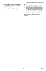
... . When the keys are released, these two-digit codes are no longer displayed. 3. M14688 5. Press the ▲ key to manufacturer's recommendations. • For compressor protection, during power interruption and on the fan through a limit control. When using an electric heat thermostat, the fan starts immediately. 3. NOTE: After exiting installer setup mode, slide the System switch to the desired position and change heating/cooling temperature control to scroll between 1, 3, 4, 5, 6, 9, or 12. Press...
... . When the keys are released, these two-digit codes are no longer displayed. 3. M14688 5. Press the ▲ key to manufacturer's recommendations. • For compressor protection, during power interruption and on the fan through a limit control. When using an electric heat thermostat, the fan starts immediately. 3. NOTE: After exiting installer setup mode, slide the System switch to the desired position and change heating/cooling temperature control to scroll between 1, 3, 4, 5, 6, 9, or 12. Press...
Installation Instructions
Page 7
... FAN switch to Auto. In heating, the fan is controlled directly by the heating equipment and may start a few minutes after the heating equipment turns on (on most systems). The fan should shut down. In cooling, the fan starts and stops with the heating equipment. Slide the FAN switch to On. T8400C, T8401C ELECTRONIC THERMOSTATS Fan 1. Press the ▲ key to the thermostat. 7 69-1740 Cooling system should run continuously. 2. When using an electric heat thermostat...
... FAN switch to Auto. In heating, the fan is controlled directly by the heating equipment and may start a few minutes after the heating equipment turns on (on most systems). The fan should shut down. In cooling, the fan starts and stops with the heating equipment. Slide the FAN switch to On. T8400C, T8401C ELECTRONIC THERMOSTATS Fan 1. Press the ▲ key to the thermostat. 7 69-1740 Cooling system should run continuously. 2. When using an electric heat thermostat...
Installation Instructions
Page 8
Honeywell Limited-Honeywell Limitée 1985 Douglas Drive North 35 Dynamic Drive Golden Valley, MN 55422 Scarborough, Ontario M1V 4Z9 69-1740 J.S. 6-04 www.honeywell.com/yourhome Automation and Control Solutions Honeywell International Inc.
Honeywell Limited-Honeywell Limitée 1985 Douglas Drive North 35 Dynamic Drive Golden Valley, MN 55422 Scarborough, Ontario M1V 4Z9 69-1740 J.S. 6-04 www.honeywell.com/yourhome Automation and Control Solutions Honeywell International Inc.


