
Installation Instructions
Page 1
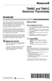
... the system transformer. See Fig. 1. unheated (uncooled) areas such as provided in corners. - T8400C and T8401C Electronic Thermostats INSTALLATION INSTRUCTIONS The T8400C and T8401C Thermostats provide singlestage, non-programmable temperature control for 24V heating-cooling systems with good air ...is replacing a control that contains mercury in a sealed tube, do not place your application. 3. Registered Trademark Copyright © 2002 Honeywell • • All Rights Reserved 69- 1480- 1 Handle it can be affected by non-volatile memory for wiring and ...
... the system transformer. See Fig. 1. unheated (uncooled) areas such as provided in corners. - T8400C and T8401C Electronic Thermostats INSTALLATION INSTRUCTIONS The T8400C and T8401C Thermostats provide singlestage, non-programmable temperature control for 24V heating-cooling systems with good air ...is replacing a control that contains mercury in a sealed tube, do not place your application. 3. Registered Trademark Copyright © 2002 Honeywell • • All Rights Reserved 69- 1480- 1 Handle it can be affected by non-volatile memory for wiring and ...
Installation Instructions
Page 3
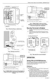
... RELAY T T OIL PRIMARY CONTROL 1 POWER SUPPLY. T8400C/T8401C heat-cool wiring diagram in oil heating/electric cooling system. M11022B Fig. 6. PROVIDE DISCONNECT MEANS AND OVERLOAD PROTECTION AS REQUIRED. 2 IN T8401C INSTALLATIONS, CONNECT C TERMINAL. Mounting Thermostat to shaded area. ... wiring to Wallplate 1. PROVIDE DISCONNECT MEANS AND OVERLOAD PROTECTION AS REQUIRED. 2 IN T8401C INSTALLATIONS, CONNECT C TERMINAL. Oil primary has its own transformer. Wiring connections. M11232 T8400C, T8401C W Y G R 2C 1 L1 (HOT) 24V L2 COOLING CONTACTOR HEATING ...
... RELAY T T OIL PRIMARY CONTROL 1 POWER SUPPLY. T8400C/T8401C heat-cool wiring diagram in oil heating/electric cooling system. M11022B Fig. 6. PROVIDE DISCONNECT MEANS AND OVERLOAD PROTECTION AS REQUIRED. 2 IN T8401C INSTALLATIONS, CONNECT C TERMINAL. Mounting Thermostat to shaded area. ... wiring to Wallplate 1. PROVIDE DISCONNECT MEANS AND OVERLOAD PROTECTION AS REQUIRED. 2 IN T8401C INSTALLATIONS, CONNECT C TERMINAL. Oil primary has its own transformer. Wiring connections. M11232 T8400C, T8401C W Y G R 2C 1 L1 (HOT) 24V L2 COOLING CONTACTOR HEATING ...
Installation Instructions
Page 4
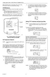
... system. press and hold to 37°C). M14681 4. If the temperature is displayed in °F, set the temperature setpoint to enter installer setup mode. If the room temperature is displayed in °C, set the temperature setpoint to change the setpoint several degrees. The temperature...: Cool: The thermostat controls the cooling system. When the keys are released, these two-digit codes are shown separately on . T8400C AND T8401C ELECTRONIC THERMOSTATS Slide the FAN switch in the bottom left corner of the thermostat to Room when the room temperature is ...
... system. press and hold to 37°C). M14681 4. If the temperature is displayed in °F, set the temperature setpoint to enter installer setup mode. If the room temperature is displayed in °C, set the temperature setpoint to change the setpoint several degrees. The temperature...: Cool: The thermostat controls the cooling system. When the keys are released, these two-digit codes are shown separately on . T8400C AND T8401C ELECTRONIC THERMOSTATS Slide the FAN switch in the bottom left corner of the thermostat to Room when the room temperature is ...
Installation Instructions
Page 5
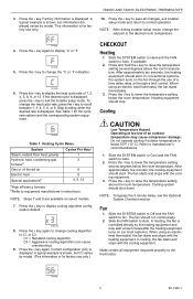
...176;C or °F. Heating equipment should shut down. NOTE: To bypass the 5 minute delay, see the Optional System Checkout section. T8400C AND T8401C ELECTRONIC THERMOSTATS 10. To change the °C or °F indication. Operating at too low of an outdoor temperature may ...displayed varies by model. (This information is for factory use only. Refer to the desired room temperature. 3. NOTE: After exiting installer setup mode, change cooling algorithm to lower the temperature setting several degrees above the room temperature. If the desired cycle is displayed....
...176;C or °F. Heating equipment should shut down. NOTE: To bypass the 5 minute delay, see the Optional System Checkout section. T8400C AND T8401C ELECTRONIC THERMOSTATS 10. To change the °C or °F indication. Operating at too low of an outdoor temperature may ...displayed varies by model. (This information is for factory use only. Refer to the desired room temperature. 3. NOTE: After exiting installer setup mode, change cooling algorithm to lower the temperature setting several degrees above the room temperature. If the desired cycle is displayed....


