
Installation Instructions
Page 3
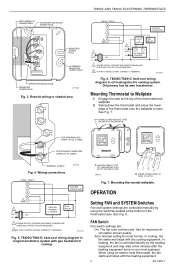
...an electric heat thermostat, the fan starts and stops with the heating equipment. 3 69-1480-1 See Fig. 7. T8400C/T8401C heat-cool wiring diagram in oil heating/electric cooling system. M18416 B PRESS LOWER EDGE OF CASE TO LATCH. See Fig. 8. Use for... MOUNTING SCREW HOLE W Y G R C MOUNTING SCREW HOLE ALTERNATE MOUNTING SCREW HOLE WIRING ENTRANCE HOLE MOUNTING SCREW HOLE M11023 Fig. 3. T8400C/T8401C heat-cool wiring diagram in single transformer system with the cooling equipment. M11232 T8400C, T8401C W Y G R 2C 1 L1 (HOT) 24V L2 COOLING CONTACTOR HEATING...
...an electric heat thermostat, the fan starts and stops with the heating equipment. 3 69-1480-1 See Fig. 7. T8400C/T8401C heat-cool wiring diagram in oil heating/electric cooling system. M18416 B PRESS LOWER EDGE OF CASE TO LATCH. See Fig. 8. Use for... MOUNTING SCREW HOLE W Y G R C MOUNTING SCREW HOLE ALTERNATE MOUNTING SCREW HOLE WIRING ENTRANCE HOLE MOUNTING SCREW HOLE M11023 Fig. 3. T8400C/T8401C heat-cool wiring diagram in single transformer system with the cooling equipment. M11232 T8400C, T8401C W Y G R 2C 1 L1 (HOT) 24V L2 COOLING CONTACTOR HEATING...


