
Installation Instructions
Page 1
...trash. drafts or dead spots behind the thermostat. unheated (uncooled) areas such as provided in a sealed tube. The T8400C SUPER TRADELINE® model also includes two decorator cover plates for instructions regarding recycling and the proper disposal of an old ..., wallplate (for wiring and mounting thermostat) and owner's guide. Failure to cool. concealed pipes and chimneys. - This thermostat is powered directly from heat to follow them could damage the product or cause a hazardous condition. 2. Registered Trademark Copyright © 2002 Honeywell • •...
...trash. drafts or dead spots behind the thermostat. unheated (uncooled) areas such as provided in a sealed tube. The T8400C SUPER TRADELINE® model also includes two decorator cover plates for instructions regarding recycling and the proper disposal of an old ..., wallplate (for wiring and mounting thermostat) and owner's guide. Failure to cool. concealed pipes and chimneys. - This thermostat is powered directly from heat to follow them could damage the product or cause a hazardous condition. 2. Registered Trademark Copyright © 2002 Honeywell • •...
Installation Instructions
Page 2
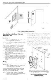
... TRADELINE® models have the cover plate. Mount decorator cover plate (SUPER TRADELINE® model only), wallplate, T8400C or T8401C, and the screws provided (see Wiring section. see Fig. 2) as follows: 1. The shape of the terminals permits insertion of thermostat. NOTE: To.... 4. DECORATOR COVER PLATE WALL 1 2 WALL ANCHORS (2) Wiring IMPORTANT Use an 18-gauge maximum wire for typical wiring hookups. 5-3/4 IN. Disconnect the power supply to Fig. 5 and 6 for wiring the T8400C and T8401C Thermostats. After wiring the wallplate, plug the hole to prevent drafts from the ...
... TRADELINE® models have the cover plate. Mount decorator cover plate (SUPER TRADELINE® model only), wallplate, T8400C or T8401C, and the screws provided (see Wiring section. see Fig. 2) as follows: 1. The shape of the terminals permits insertion of thermostat. NOTE: To.... 4. DECORATOR COVER PLATE WALL 1 2 WALL ANCHORS (2) Wiring IMPORTANT Use an 18-gauge maximum wire for typical wiring hookups. 5-3/4 IN. Disconnect the power supply to Fig. 5 and 6 for wiring the T8400C and T8401C Thermostats. After wiring the wallplate, plug the hole to prevent drafts from the ...
Installation Instructions
Page 3
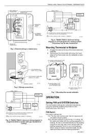
... CONTACTOR HEATING PRIMARY CONTROL FAN RELAY 1 POWER SUPPLY. See Fig. 8. Restrict wiring to Wallplate 1. Engage the tabs at the bottom of the thermostat case. T8400C/T8401C heat-cool wiring diagram in oil heating/electric cooling system. Mounting thermostat wallplate. T8400C/T8401C heat-cool wiring diagram in single transformer system with gas heat/electric cooling. DASHED...
... CONTACTOR HEATING PRIMARY CONTROL FAN RELAY 1 POWER SUPPLY. See Fig. 8. Restrict wiring to Wallplate 1. Engage the tabs at the bottom of the thermostat case. T8400C/T8401C heat-cool wiring diagram in oil heating/electric cooling system. Mounting thermostat wallplate. T8400C/T8401C heat-cool wiring diagram in single transformer system with gas heat/electric cooling. DASHED...


