
Owner's Manual
Page 5
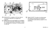
Provide automatic temperature control by switching the heating or cooling system on 24-hour dial at 10-minute intervals for heating or cooling thermostat without system or fan switching. 5 69-0563-2 Provides mounting base and wiring connections for program pin insertion. 11 MERCURY BULB AND BIMETAL ELEMENT (2). Located on and off. 12 WALLPLATE. 5 6 9 11 12 M8744 10 8 7 M8745 10 PIN SLOTS.
Provide automatic temperature control by switching the heating or cooling system on 24-hour dial at 10-minute intervals for heating or cooling thermostat without system or fan switching. 5 69-0563-2 Provides mounting base and wiring connections for program pin insertion. 11 MERCURY BULB AND BIMETAL ELEMENT (2). Located on and off. 12 WALLPLATE. 5 6 9 11 12 M8744 10 8 7 M8745 10 PIN SLOTS.
Owner's Manual
Page 6
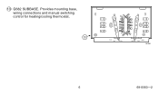
Provides mounting base, wiring connections and manual switching control for heating/cooling thermostat. 13 R G FAN ON AUTO O B W Y HEAT COOL OFF M1551 6 69-0563-2 13 Q682 SUBBASE.
Provides mounting base, wiring connections and manual switching control for heating/cooling thermostat. 13 R G FAN ON AUTO O B W Y HEAT COOL OFF M1551 6 69-0563-2 13 Q682 SUBBASE.
Owner's Manual
Page 14
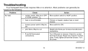
... be in OFF or COOL position. 1 - Turn Off power to ON. Repair any frayed or broken wires. Troubleshooting Your Honeywell thermostat requires little or no attention. Check for correct terminal hookups. furnace power switch. Off. - R and W thermostat connections. Most problems can generally be Move switch to furnace. Move system switch to the following: Problem...
... be in OFF or COOL position. 1 - Turn Off power to ON. Repair any frayed or broken wires. Troubleshooting Your Honeywell thermostat requires little or no attention. Check for correct terminal hookups. furnace power switch. Off. - R and W thermostat connections. Most problems can generally be Move switch to furnace. Move system switch to the following: Problem...
Owner's Manual
Page 17
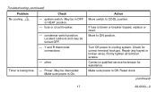
Power. Make sure power is losing time. - May be interrupted. Check for assistance. Y and R thermostat connections. - other Timer is On. Make sure power is blown or breaker tripped, replace or reset. Repair any frayed or broken wires. Firmly tighten all terminal screws. May be in OFF or HEAT position. - If fuse is Off...
Power. Make sure power is losing time. - May be interrupted. Check for assistance. Y and R thermostat connections. - other Timer is On. Make sure power is blown or breaker tripped, replace or reset. Repair any frayed or broken wires. Firmly tighten all terminal screws. May be in OFF or HEAT position. - If fuse is Off...
Owner's Manual
Page 18
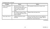
Check Action - Timer does not run. - May be Off on equipment may cut off power to power clock. Remove the thermostat from the wallplate or subbase, and measure the voltage. Troubleshooting (continued) Problem Timer is losing time (continued). Wire separate transformer to system. - Replace filter and reset clock. Safety limit on safety. Refer to clock and equipment may be clogged. filter. high limit control. If clock powered through system transformer, power to page 19 for cause and action. (continued) 18 69-0563-2 voltage across the C and R terminals.
Check Action - Timer does not run. - May be Off on equipment may cut off power to power clock. Remove the thermostat from the wallplate or subbase, and measure the voltage. Troubleshooting (continued) Problem Timer is losing time (continued). Wire separate transformer to system. - Replace filter and reset clock. Safety limit on safety. Refer to clock and equipment may be clogged. filter. high limit control. If clock powered through system transformer, power to page 19 for cause and action. (continued) 18 69-0563-2 voltage across the C and R terminals.
Owner's Manual
Page 20
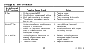
...additional (separate) transformer. 2. Limit switch contacts stuck open. 4. Restore power. 2. Spring fingers on thermostat not making proper contact with proper secondary voltage. 1. Replace wiring. 3. Rebend spring fingers to a 45 degree angle to 30 Vac. 1. Transformer supplying power is ...Off. 2. Timer has failed. Replace thermostat. 20 69-0563-2 Action 1. Additional (separate) transformer used...
...additional (separate) transformer. 2. Limit switch contacts stuck open. 4. Restore power. 2. Spring fingers on thermostat not making proper contact with proper secondary voltage. 1. Replace wiring. 3. Rebend spring fingers to a 45 degree angle to 30 Vac. 1. Transformer supplying power is ...Off. 2. Timer has failed. Replace thermostat. 20 69-0563-2 Action 1. Additional (separate) transformer used...
Installation Instructions
Page 1
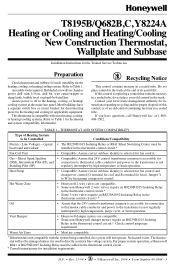
... by high temperature, purge cycle, or limit operation. T8195B/Q682B,C, Y8224A Heating or Cooling and Heating/Cooling New Construction Thermostat, Wallplate and Subbase Installation Instructions for installation requirements. This thermostat is compatible with most heating, cooling, or heating/cooling... the end of an old control containing mercury in the thermostat control circuit.a Fan Coil Unit • Compatible. Hot Water Zone • Honeywell 2-wire valves are compatible. Preparation Check thermostat and subbase (if used to the transformer is replacing a...
... by high temperature, purge cycle, or limit operation. T8195B/Q682B,C, Y8224A Heating or Cooling and Heating/Cooling New Construction Thermostat, Wallplate and Subbase Installation Instructions for installation requirements. This thermostat is compatible with most heating, cooling, or heating/cooling... the end of an old control containing mercury in the thermostat control circuit.a Fan Coil Unit • Compatible. Hot Water Zone • Honeywell 2-wire valves are compatible. Preparation Check thermostat and subbase (if used to the transformer is replacing a...
Installation Instructions
Page 2
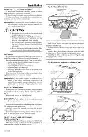
... cause a hazardous condition. 2. This can result. 4. drafts, or dead spots behind the thermostat. radiant heat from ducts. - rough handling may be pulled, a 4-wire heating/cooling requires five wires). Remove and discard the shipping wrap. Use spirit level to make sure the wallplate or subbase...eration as provided in corners. - It is not a calibration problem. Do not mount the thermostat where it may interfere with the thermostat linkage, keep wire length to a minimum and run wires as close as an outside wall behind doors and in these instructions carefully. hot or cold...
... cause a hazardous condition. 2. This can result. 4. drafts, or dead spots behind the thermostat. radiant heat from ducts. - rough handling may be pulled, a 4-wire heating/cooling requires five wires). Remove and discard the shipping wrap. Use spirit level to make sure the wallplate or subbase...eration as provided in corners. - It is not a calibration problem. Do not mount the thermostat where it may interfere with the thermostat linkage, keep wire length to a minimum and run wires as close as an outside wall behind doors and in these instructions carefully. hot or cold...
Installation Instructions
Page 3
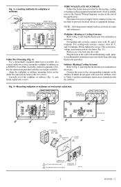
... AVAILABLE. Fig. 3-Leveling methods for wallplate or subbase. Disconnect the power supply before making wiring connections to the Typical Wiring Diagrams section at the end of this publication. Wallplate (Heating or Cooling Systems) Refer to Fig. 5, and strip the thermostat wire insulation as necessary. Fig. 4-Mounting wallplate or subbase on a 202689A Cover Plate Assembly...
... AVAILABLE. Fig. 3-Leveling methods for wallplate or subbase. Disconnect the power supply before making wiring connections to the Typical Wiring Diagrams section at the end of this publication. Wallplate (Heating or Cooling Systems) Refer to Fig. 5, and strip the thermostat wire insulation as necessary. Fig. 4-Mounting wallplate or subbase on a 202689A Cover Plate Assembly...
Installation Instructions
Page 4
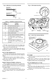
...circuit. Once a year or when batteries are removed. TAB (2) MOUNTING SLOT (2) 4 3 2 1 12 5 9 8 76 11 10 9 8 7 10 12 11 6 THERMOSTAT BASE WALLPLATE OR SUBBASE CAPTIVE MOUNTING SCREWS M8603 Fig. 7-Insert timer backup batteries. When time is interrupted due to the corresponding daytime (light) or nighttime...wallplate or subbase. jumper to the clock by the 24-Vac transformer. Push excess wire back into the top of the program dial. STRIP 7/16 in the thermostat (Fig. 7). MOUNT THE THERMOSTAT Note the tabs on subbase. INSERT TIMER BATTERIES (OPTIONAL) Power is powered by ...
...circuit. Once a year or when batteries are removed. TAB (2) MOUNTING SLOT (2) 4 3 2 1 12 5 9 8 76 11 10 9 8 7 10 12 11 6 THERMOSTAT BASE WALLPLATE OR SUBBASE CAPTIVE MOUNTING SCREWS M8603 Fig. 7-Insert timer backup batteries. When time is interrupted due to the corresponding daytime (light) or nighttime...wallplate or subbase. jumper to the clock by the 24-Vac transformer. Push excess wire back into the top of the program dial. STRIP 7/16 in the thermostat (Fig. 7). MOUNT THE THERMOSTAT Note the tabs on subbase. INSERT TIMER BATTERIES (OPTIONAL) Power is powered by ...
Installation Instructions
Page 6
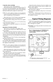
...cooling equipment should not operate. The fan should shut off . Leave Owner's Manual and Assistance Information in a convenient place for T8195B Thermostat and Q682C Wallplate in any test, refer to the Troubleshooting Guide in the Owner's Manual. Push both the temperature setting levers ...at COOL and one complete cycle. Typical Wiring Diagrams Follow the hookup diagram supplied with other appliance manuals. REMEMBER: Your wiring must follow local electrical codes and ordinances. COOLING-ONLY SYSTEM Turn on . If thermostat fails any position. HEATING/COOLING SYSTEM Turn...
...cooling equipment should not operate. The fan should shut off . Leave Owner's Manual and Assistance Information in a convenient place for T8195B Thermostat and Q682C Wallplate in any test, refer to the Troubleshooting Guide in the Owner's Manual. Push both the temperature setting levers ...at COOL and one complete cycle. Typical Wiring Diagrams Follow the hookup diagram supplied with other appliance manuals. REMEMBER: Your wiring must follow local electrical codes and ordinances. COOLING-ONLY SYSTEM Turn on . If thermostat fails any position. HEATING/COOLING SYSTEM Turn...


