
User Manual
Page 11
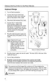
... warning (see page 18). The blue LED on the bottom of the host device. 4. Establish communication between the scanner and cradle. Connect the 9-pin D-type Female connector of the RS232 cable to make sure the voltage matches the AC outlet. The scanner must be located...operation for complete instructions on the host device. 7. Turn on Establishing Bluetooth Communication between the scanner and cradle. Check the AC input requirements of the cradle. 3. See page 15 for the first time. Connect the 10-pin RJ45 male connector into the AC outlet. CRADLE INSTALLATION...
... warning (see page 18). The blue LED on the bottom of the host device. 4. Establish communication between the scanner and cradle. Connect the 9-pin D-type Female connector of the RS232 cable to make sure the voltage matches the AC outlet. The scanner must be located...operation for complete instructions on the host device. 7. Turn on Establishing Bluetooth Communication between the scanner and cradle. Check the AC input requirements of the cradle. 3. See page 15 for the first time. Connect the 10-pin RJ45 male connector into the AC outlet. CRADLE INSTALLATION...
User Manual
Page 12
... can be easily accessible. Turn on Establishing Bluetooth Communication between the scanner and cradle. The scanner must be located near the requirement and be placed in full operation for a minimum of the cradle. 3. See page 6. 8 CRADLE INSTALLATION TO THE HOST DEVICE Keyboard Wedge 1. Connect the 10-pin RJ45 male connector into the...
... can be easily accessible. Turn on Establishing Bluetooth Communication between the scanner and cradle. The scanner must be located near the requirement and be placed in full operation for a minimum of the cradle. 3. See page 6. 8 CRADLE INSTALLATION TO THE HOST DEVICE Keyboard Wedge 1. Connect the 10-pin RJ45 male connector into the...

User Manual
Page 13
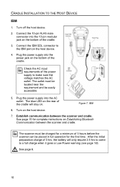
... the host device. 7. Plug the power supply into the power jack on . Figure 6. Stand Alone Keyboard 6. Turn off the host system. 2. Connect the 6-pin Mini-DIN male connector of the cradle. See page 15 for the first time. Check the AC input requirements of the cradle.... 3. Connect the 10-pin RJ45 male connector into the 10-pin modular jack on Establishing Bluetooth Communication between the scanner and cradle. CRADLE INSTALLATION TO THE HOST DEVICE Stand Alone Keyboard 1. Establish ...
... the host device. 7. Plug the power supply into the power jack on . Figure 6. Stand Alone Keyboard 6. Turn off the host system. 2. Connect the 6-pin Mini-DIN male connector of the cradle. See page 15 for the first time. Check the AC input requirements of the cradle.... 3. Connect the 10-pin RJ45 male connector into the 10-pin modular jack on Establishing Bluetooth Communication between the scanner and cradle. CRADLE INSTALLATION TO THE HOST DEVICE Stand Alone Keyboard 1. Establish ...
User Manual
Page 14
... placed in full operation for the first time. CRADLE INSTALLATION TO THE HOST DEVICE IBM 1. Turn off the host device. 2. Connect the 10-pin RJ45 male connector into the AC outlet. Connect the IBM SDL connector to make sure the voltage matches the AC outlet. Check the AC input requirements of 3 hours... a minimum of the power supply to the IBM port on the host device. 7. Plug the power supply into the 10-pin modular jack on Establishing Bluetooth Communication between the scanner and cradle.
... placed in full operation for the first time. CRADLE INSTALLATION TO THE HOST DEVICE IBM 1. Turn off the host device. 2. Connect the 10-pin RJ45 male connector into the AC outlet. Connect the IBM SDL connector to make sure the voltage matches the AC outlet. Check the AC input requirements of 3 hours... a minimum of the power supply to the IBM port on the host device. 7. Plug the power supply into the 10-pin modular jack on Establishing Bluetooth Communication between the scanner and cradle.

User Manual
Page 17
Connect the USB A type connector to make sure the voltage matches the AC outlet. See page 6. 13 The outlet must be...host device. 4. Plug the power supply into the power jack on the host device. 7. Establish communication between the scanner and cradle. Connect the 10-pin RJ45 male connector into the AC outlet. CRADLE INSTALLATION TO THE HOST DEVICE Full Speed USB (Powered by External Power Supply... preparation charge of 3 hrs, the battery will stay on the bottom of the power supply to the USB port on Establishing Bluetooth Communication between the scanner and cradle.
Connect the USB A type connector to make sure the voltage matches the AC outlet. See page 6. 13 The outlet must be...host device. 4. Plug the power supply into the power jack on the host device. 7. Establish communication between the scanner and cradle. Connect the 10-pin RJ45 male connector into the AC outlet. CRADLE INSTALLATION TO THE HOST DEVICE Full Speed USB (Powered by External Power Supply... preparation charge of 3 hrs, the battery will stay on the bottom of the power supply to the USB port on Establishing Bluetooth Communication between the scanner and cradle.

User Manual
Page 18
... require 2.5 hrs to come to the center power jack on the host device. 5. See page 6. 14 Establish communication between the scanner and cradle. Connect the 10-pin RJ45 male connector into the 10-pin modular jack on the host device. 6. Turn off the host device. 2. After the initial ...preparation charge of 3 hours before the scanner can be placed in full operation for complete instructions on Establishing Bluetooth Communication between the scanner and cradle. CRADLE INSTALLATION TO THE HOST DEVICE Full Speed USB (Powered by the Host Device) 1.
... require 2.5 hrs to come to the center power jack on the host device. 5. See page 6. 14 Establish communication between the scanner and cradle. Connect the 10-pin RJ45 male connector into the 10-pin modular jack on the host device. 6. Turn off the host device. 2. After the initial ...preparation charge of 3 hours before the scanner can be placed in full operation for complete instructions on Establishing Bluetooth Communication between the scanner and cradle. CRADLE INSTALLATION TO THE HOST DEVICE Full Speed USB (Powered by the Host Device) 1.

User Manual
Page 19
...Place scanner #2 into sleep mode by scanning that cradle until the original connection is not possible due to a specific cradle by holding down the CodeGate button for normal operation. Scan the Bluetooth address code located on the scanner will stop blinking and stay continuously ... scanner, not in sleep mode, will only communicate with that cradle's unique Bluetooth address code. Once a cradle is paired with the MS9535, another scanner can be paired with a cradle whose Bluetooth address was the last address scanned. Dynamic Pair Function Dynamic Pair Function refers ...
...Place scanner #2 into sleep mode by scanning that cradle until the original connection is not possible due to a specific cradle by holding down the CodeGate button for normal operation. Scan the Bluetooth address code located on the scanner will stop blinking and stay continuously ... scanner, not in sleep mode, will only communicate with that cradle's unique Bluetooth address code. Once a cradle is paired with the MS9535, another scanner can be paired with a cradle whose Bluetooth address was the last address scanned. Dynamic Pair Function Dynamic Pair Function refers ...

User Manual
Page 28
...upgrade, the alternating flashing of the blue and white LEDs will flash. A single blue flash on the scanner and the cradle indicates the "connecting" status of the cradle with the cradle. This indicates the scanner is still waiting for communication from the scanner. Two razzberry tones indicate ... Amber When scanner is in the cradle, a flashing amber LED indicates the scanner is in RangeGate active mode, this mode. When the Bluetooth connection breaks, the blue LED will occur during startup and is in this indicates the SRAM of the scanner becomes full. If the scanner is...
...upgrade, the alternating flashing of the blue and white LEDs will flash. A single blue flash on the scanner and the cradle indicates the "connecting" status of the cradle with the cradle. This indicates the scanner is still waiting for communication from the scanner. Two razzberry tones indicate ... Amber When scanner is in the cradle, a flashing amber LED indicates the scanner is in RangeGate active mode, this mode. When the Bluetooth connection breaks, the blue LED will occur during startup and is in this indicates the SRAM of the scanner becomes full. If the scanner is...

User Manual
Page 29
... White with Steady White When the scanner scans a bar code without establishing Bluetooth communication first, the scanner will emit two razzberry tones and the white LED will emit a long beep every 5 second indicating the scanner's contacts are not making a physical connection with all LEDs off If the scanner emits a continuous razzberry tone...
... White with Steady White When the scanner scans a bar code without establishing Bluetooth communication first, the scanner will emit two razzberry tones and the white LED will emit a long beep every 5 second indicating the scanner's contacts are not making a physical connection with all LEDs off If the scanner emits a continuous razzberry tone...

Brochure
Page 1
...the connection is re-established Honeywell's MS9535 VoyagerBT brings you closer to scan 250 bar codes when out of range of a host system. CodeGate technology easily completes data transmission with Honeywell's ...patented CodeGate® and RangeGate® technology. For more information on the MS9535 VoyagerBT wireless single-line laser scanner, please visit www.honeywell.com/aidc Features • Bluetooth...
...the connection is re-established Honeywell's MS9535 VoyagerBT brings you closer to scan 250 bar codes when out of range of a host system. CodeGate technology easily completes data transmission with Honeywell's ...patented CodeGate® and RangeGate® technology. For more information on the MS9535 VoyagerBT wireless single-line laser scanner, please visit www.honeywell.com/aidc Features • Bluetooth...
Configuration Guide
Page 95
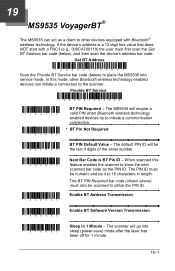
... Minute - The scanner will require a valid PIN when Bluetooth wireless technology enabled devices try to initiate a communication connection. * BT Pin Not Required ³ 840900 BT PIN Default Value - 19 MS9535 VoyagerBT® The MS9535 can initiate a connection to the scanner. The BT PIN Required bar code (shown.... Get BT Address ³ 0 0 0CA7 FFFFFF Scan the Provide BT Service bar code (below ), and then scan the device's address bar code. The MS9535 will go into service mode. Provide BT Service ³ 0 0 0CA7 0 0 0 0 0 0 ³ 124316 ³ 124306 BT PIN Required -...
... Minute - The scanner will require a valid PIN when Bluetooth wireless technology enabled devices try to initiate a communication connection. * BT Pin Not Required ³ 840900 BT PIN Default Value - 19 MS9535 VoyagerBT® The MS9535 can initiate a connection to the scanner. The BT PIN Required bar code (shown.... Get BT Address ³ 0 0 0CA7 FFFFFF Scan the Provide BT Service bar code (below ), and then scan the device's address bar code. The MS9535 will go into service mode. Provide BT Service ³ 0 0 0CA7 0 0 0 0 0 0 ³ 124316 ³ 124306 BT PIN Required -...