
User Manual
Page 1
METROLOGIC INSTRUMENTS, INC. MS9535 VoyagerBT ® Series Single-Line Hand Held Laser Scanner Installation and User's Guide
METROLOGIC INSTRUMENTS, INC. MS9535 VoyagerBT ® Series Single-Line Hand Held Laser Scanner Installation and User's Guide

User Manual
Page 2
Trademarks Metrologic is a registered trademark of Metrologic Instruments, Inc. Products identified in this work may quote brief passages in a review, or provided for in any form or by any means without prior written consent, except by Metrologic Instruments, Inc. No part of this document are hereby acknowledged as trademarks, registered or otherwise, of Metrologic Instruments, Inc. All rights reserved. or their respective companies. Copyright © 2006 by reviewer, who may be reproduced, transmitted, or stored in the Copyright Act of 1976.
Trademarks Metrologic is a registered trademark of Metrologic Instruments, Inc. Products identified in this work may quote brief passages in a review, or provided for in any form or by any means without prior written consent, except by Metrologic Instruments, Inc. No part of this document are hereby acknowledged as trademarks, registered or otherwise, of Metrologic Instruments, Inc. All rights reserved. or their respective companies. Copyright © 2006 by reviewer, who may be reproduced, transmitted, or stored in the Copyright Act of 1976.

User Manual
Page 3
... the Host Device 14 Establishing Bluetooth Communication Between the Scanner and the Cradle 15 Dynamic Pair Function 15 When the MS9535 Acts as a Client to Other Bluetooth Devices 16 When the MS9535 Acts as a Server to Other Bluetooth Devices 17 The MI9535-5xx Receiver / Charger Cradle Charging Guidelines and Low Battery Indicators...
... the Host Device 14 Establishing Bluetooth Communication Between the Scanner and the Cradle 15 Dynamic Pair Function 15 When the MS9535 Acts as a Client to Other Bluetooth Devices 16 When the MS9535 Acts as a Server to Other Bluetooth Devices 17 The MI9535-5xx Receiver / Charger Cradle Charging Guidelines and Low Battery Indicators...
User Manual
Page 4
Communication Parameters 35 Upgrading the Flash ROM Firmware 40 Configuration Modes 40 Cradle and Cable Terminations Cradle Pinout Connections 41 Cable Connector Configurations 44 Regulatory Compliance 47 Safety...47 EMC...48 Limited Warranty 50 Patents ...51 Index ...52 Contact Information and Office Locations 54 iii TABLE OF CONTENTS Indicators ...22 Audible...22 Visual...23 Failure Modes 25 Depth of Field by Bar Code Element Width 26 IR Activation Range 27 Cable Removal 28 Cradle Wall Mount 28 Troubleshooting Guide 29 Design Specifications 33 Default Settings -
Communication Parameters 35 Upgrading the Flash ROM Firmware 40 Configuration Modes 40 Cradle and Cable Terminations Cradle Pinout Connections 41 Cable Connector Configurations 44 Regulatory Compliance 47 Safety...47 EMC...48 Limited Warranty 50 Patents ...51 Index ...52 Contact Information and Office Locations 54 iii TABLE OF CONTENTS Indicators ...22 Audible...22 Visual...23 Failure Modes 25 Depth of Field by Bar Code Element Width 26 IR Activation Range 27 Cable Removal 28 Cradle Wall Mount 28 Troubleshooting Guide 29 Design Specifications 33 Default Settings -

User Manual
Page 5
... this mode, the scanner can also optionally communicate to 12,000 scans. VoyagerBT includes the ability to 35 hours before the batteries require recharging. INTRODUCTION MS9535 VoyagerBT® laser bar code scanner is a new member of an automatic trigger and CodeGate, the VoyagerBT has incorporated the latest Bluetooth® wireless technology...
... this mode, the scanner can also optionally communicate to 12,000 scans. VoyagerBT includes the ability to 35 hours before the batteries require recharging. INTRODUCTION MS9535 VoyagerBT® laser bar code scanner is a new member of an automatic trigger and CodeGate, the VoyagerBT has incorporated the latest Bluetooth® wireless technology...

User Manual
Page 6
....metrologic.com. ** Configurable for Keyboard Emulation Mode or Serial Emulation Mode. INTRODUCTION Scanner and Accessories Part # MS9535-5 or MS9535-5M 70-79004x 00-02544x 70-73524 BASIC KIT Description VoyagerBT Scanner or VoyagerBT Scanner with Memory MS9535 VoyagerBT Wireless Hand Held Laser Scanner Installation and User's Guide* MetroSelect Single-Line Configuration Guide* Wrist...
....metrologic.com. ** Configurable for Keyboard Emulation Mode or Serial Emulation Mode. INTRODUCTION Scanner and Accessories Part # MS9535-5 or MS9535-5M 70-79004x 00-02544x 70-73524 BASIC KIT Description VoyagerBT Scanner or VoyagerBT Scanner with Memory MS9535 VoyagerBT Wireless Hand Held Laser Scanner Installation and User's Guide* MetroSelect Single-Line Configuration Guide* Wrist...

User Manual
Page 7
INTRODUCTION Scanner and Accessories OPTIONAL ACCESSORIES Part # Description AC to DC Power Transformer- Regulated 5VDC @ 2A Output 46-46881 Power Supply, China 46-46880 Power Supply, United Kingdom 46-46879 Power Supply, Continental Europe 46-46882 Power Supply, Australia 46-46878 Power Supply, United States 46-46842 54-54000x-N Power Supply, Japan Communication Cable RS232 / Light Pen Cable, short strain relief 54-54002x Keyboard Wedge Cable, short strain relief 52-52828x Low Speed USB Cable, short strain relief 54-54250x-N IBM Cable, straight 54-54073x Full Speed ...
INTRODUCTION Scanner and Accessories OPTIONAL ACCESSORIES Part # Description AC to DC Power Transformer- Regulated 5VDC @ 2A Output 46-46881 Power Supply, China 46-46880 Power Supply, United Kingdom 46-46879 Power Supply, Continental Europe 46-46882 Power Supply, Australia 46-46878 Power Supply, United States 46-46842 54-54000x-N Power Supply, Japan Communication Cable RS232 / Light Pen Cable, short strain relief 54-54002x Keyboard Wedge Cable, short strain relief 52-52828x Low Speed USB Cable, short strain relief 54-54250x-N IBM Cable, straight 54-54073x Full Speed ...
User Manual
Page 8
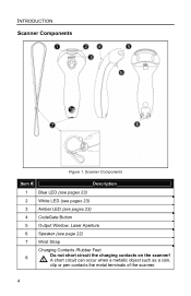
INTRODUCTION Scanner Components Figure 1. Scanner Components Item # Description 1 Blue LED (see pages 23) 2 White LED (see pages 23) 3 Amber LED (see pages 23) 4 CodeGate Button 5 Output Window, Laser Aperture 6 Speaker (see page 22) 7 Wrist Strap Charging Contacts /Rubber Feet 8 Do not short circuit the charging contacts on the scanner! A short circuit can occur when a metallic object such as a coin, clip or pen contacts the metal terminals of the scanner. 4
INTRODUCTION Scanner Components Figure 1. Scanner Components Item # Description 1 Blue LED (see pages 23) 2 White LED (see pages 23) 3 Amber LED (see pages 23) 4 CodeGate Button 5 Output Window, Laser Aperture 6 Speaker (see page 22) 7 Wrist Strap Charging Contacts /Rubber Feet 8 Do not short circuit the charging contacts on the scanner! A short circuit can occur when a metallic object such as a coin, clip or pen contacts the metal terminals of the scanner. 4
User Manual
Page 9
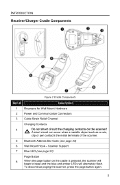
To discontinue paging the scanner, press the page button again. 5 Scanner Support 7 Blue LED (see page 23) 6 Wall Mount Hook - INTRODUCTION Receiver/Charger Cradle Components Figure 2 Cradle Components Item # Description 1 Recesses for Wall Mount Hardware 2 Power and Communication Connectors 3 Cable Strain Relief Channel Charging Contacts 4 Do not short circuit the charging contacts on the cradle is pressed, the scanner will begin to beep and the blue and amber LEDs will alternately flash. A short circuit can occur when a metallic object such as a coin, clip or pen contacts ...
To discontinue paging the scanner, press the page button again. 5 Scanner Support 7 Blue LED (see page 23) 6 Wall Mount Hook - INTRODUCTION Receiver/Charger Cradle Components Figure 2 Cradle Components Item # Description 1 Recesses for Wall Mount Hardware 2 Power and Communication Connectors 3 Cable Strain Relief Channel Charging Contacts 4 Do not short circuit the charging contacts on the cradle is pressed, the scanner will begin to beep and the blue and amber LEDs will alternately flash. A short circuit can occur when a metallic object such as a coin, clip or pen contacts ...

User Manual
Page 10
the model number, date of a bar code. INTRODUCTION Caution and Serial Number Labels The scanner and cradle have labels that provide important information including; Figure 3. Maintenance Smudges and dirt can interfere with glass cleaner sprayed onto a lint free, no-abrasive cleaning cloth. 6 To maintain compliance with applicable standards, all circuits connected to EN/IEC 60950-1. Figure 3 provides examples of these labels and their locations. Label Sample and Location Caution: To maintain compliance with standard CSA C22.2 No. 60950-1/UL 60950-1 and norm EN/IEC 60950-1, the ...
the model number, date of a bar code. INTRODUCTION Caution and Serial Number Labels The scanner and cradle have labels that provide important information including; Figure 3. Maintenance Smudges and dirt can interfere with glass cleaner sprayed onto a lint free, no-abrasive cleaning cloth. 6 To maintain compliance with applicable standards, all circuits connected to EN/IEC 60950-1. Figure 3 provides examples of these labels and their locations. Label Sample and Location Caution: To maintain compliance with standard CSA C22.2 No. 60950-1/UL 60950-1 and norm EN/IEC 60950-1, the ...

User Manual
Page 11
Check the AC input requirements of the power supply to the proper COM port of the RS232 cable to make sure the voltage matches the AC outlet. Establish communication between the scanner and cradle. Connect the 9-pin D-type Female connector of the host device. 4. Plug the power supply into the 10-pin modular jack on Establishing Bluetooth Communication between the scanner and cradle. See page 6. 7 Connect the 10-pin RJ45 male connector into the AC outlet. The outlet must be charged for a minimum of the cradle. Turn on the bottom of 3 hours before the ...
Check the AC input requirements of the power supply to the proper COM port of the RS232 cable to make sure the voltage matches the AC outlet. Establish communication between the scanner and cradle. Connect the 9-pin D-type Female connector of the host device. 4. Plug the power supply into the 10-pin modular jack on Establishing Bluetooth Communication between the scanner and cradle. See page 6. 7 Connect the 10-pin RJ45 male connector into the AC outlet. The outlet must be charged for a minimum of the cradle. Turn on the bottom of 3 hours before the ...

User Manual
Page 12
Keyboard Wedge 6. See page 6. 8 CRADLE INSTALLATION TO THE HOST DEVICE Keyboard Wedge 1. Check the AC input requirements of the power supply to the keyboard and keyboard port on Establishing Bluetooth Communication between the scanner and cradle. Turn on . 7. Plug the external power supply into the AC outlet. The outlet must be charged for a minimum of the cradle. The scanner must be located near the requirement and be placed in full operation for complete instructions on the host device. Plug the power supply into the power jack on the rear of the ...
Keyboard Wedge 6. See page 6. 8 CRADLE INSTALLATION TO THE HOST DEVICE Keyboard Wedge 1. Check the AC input requirements of the power supply to the keyboard and keyboard port on Establishing Bluetooth Communication between the scanner and cradle. Turn on . 7. Plug the external power supply into the AC outlet. The outlet must be charged for a minimum of the cradle. The scanner must be located near the requirement and be placed in full operation for complete instructions on the host device. Plug the power supply into the power jack on the rear of the ...

User Manual
Page 13
See page 15 for the first time. After the initial preparation charge of the keyboard cable to keyboard port on the bottom of the cradle. 3. Connect the 6-pin Mini-DIN male connector of 3 hrs, the battery will stay on the host device. 7. The outlet must be charged for a minimum of the power supply to a full charge when it gives a Low Power warning (see page 18). CRADLE INSTALLATION TO THE HOST DEVICE Stand Alone Keyboard 1. Turn off the host system. 2. Turn on . Plug the external power supply into the power jack on the host device. 4. Connect the 10-pin ...
See page 15 for the first time. After the initial preparation charge of the keyboard cable to keyboard port on the bottom of the cradle. 3. Connect the 6-pin Mini-DIN male connector of 3 hrs, the battery will stay on the host device. 7. The outlet must be charged for a minimum of the power supply to a full charge when it gives a Low Power warning (see page 18). CRADLE INSTALLATION TO THE HOST DEVICE Stand Alone Keyboard 1. Turn off the host system. 2. Turn on . Plug the external power supply into the power jack on the host device. 4. Connect the 10-pin ...
User Manual
Page 14
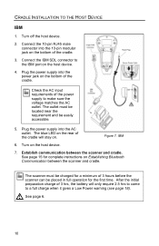
Plug the power supply into the 10-pin modular jack on the host device. 4. IBM 6. Establish communication between the scanner and cradle. See page 6. 10 See page 15 for complete instructions on . Turn off the host device. 2. Connect the IBM SDL connector to a full charge when it gives a Low Power warning (see page 18). The blue LED on the rear of the cradle will only require 2.5 hrs to come to the IBM port on the bottom of the cradle. 3. Turn on the bottom of 3 hrs, the battery will stay on Establishing Bluetooth Communication between the scanner and cradle. After ...
Plug the power supply into the 10-pin modular jack on the host device. 4. IBM 6. Establish communication between the scanner and cradle. See page 6. 10 See page 15 for complete instructions on . Turn off the host device. 2. Connect the IBM SDL connector to a full charge when it gives a Low Power warning (see page 18). The blue LED on the rear of the cradle will only require 2.5 hrs to come to the IBM port on the bottom of the cradle. 3. Turn on the bottom of 3 hrs, the battery will stay on Establishing Bluetooth Communication between the scanner and cradle. After ...
User Manual
Page 15
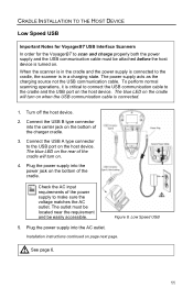
The power supply acts as the charging source not the USB communication cable. Figure 8. Plug the power supply into the center jack on when the USB communication cable is in the cradle and the power supply is connected to the cradle, the scanner is connected. 1. When the scanner is in a charging state. Plug the power supply into the power jack on the host device. Turn off the host device. 2. Low Speed USB 5. To perform normal scanning operations, it is critical to connect the USB communication cable to the cradle and the USB port on the bottom of the cradle will...
The power supply acts as the charging source not the USB communication cable. Figure 8. Plug the power supply into the center jack on when the USB communication cable is in the cradle and the power supply is connected to the cradle, the scanner is connected. 1. When the scanner is in a charging state. Plug the power supply into the power jack on the host device. Turn off the host device. 2. Low Speed USB 5. To perform normal scanning operations, it is critical to connect the USB communication cable to the cradle and the USB port on the bottom of the cradle will...

User Manual
Page 16
As a default, the MI9535-538 leaves the factory with USB Keyboard Emulation Mode enabled. See page 15 for complete instructions on the host device. 7. Scan the following bar code to configure the MI9535-538 for USB Serial Emulation Mode. ³ 316460 The scanner must be charged for the first time. Establish communication between the scanner and cradle. CRADLE INSTALLATION TO THE HOST DEVICE Low Speed USB 6. Turn on Establishing Bluetooth Communication between the scanner and cradle. After the initial preparation charge of 3 hours before the scanner can be placed in full ...
As a default, the MI9535-538 leaves the factory with USB Keyboard Emulation Mode enabled. See page 15 for complete instructions on the host device. 7. Scan the following bar code to configure the MI9535-538 for USB Serial Emulation Mode. ³ 316460 The scanner must be charged for the first time. Establish communication between the scanner and cradle. CRADLE INSTALLATION TO THE HOST DEVICE Low Speed USB 6. Turn on Establishing Bluetooth Communication between the scanner and cradle. After the initial preparation charge of 3 hours before the scanner can be placed in full ...

User Manual
Page 17
After the initial preparation charge of 3 hours before the scanner can be placed in full operation for the first time. The outlet must be easily accessible. Turn on Establishing Bluetooth Communication between the scanner and cradle. The scanner must be located near the requirement and be charged for complete instructions on the host device. 7. Plug the power supply into the power jack on the bottom of the cradle will only require 2.5 hrs to come to make sure the voltage matches the AC outlet. Full Speed USB 5. The blue LED on . 6. Figure 9. See page 15 for a...
After the initial preparation charge of 3 hours before the scanner can be placed in full operation for the first time. The outlet must be easily accessible. Turn on Establishing Bluetooth Communication between the scanner and cradle. The scanner must be located near the requirement and be charged for complete instructions on the host device. 7. Plug the power supply into the power jack on the bottom of the cradle will only require 2.5 hrs to come to make sure the voltage matches the AC outlet. Full Speed USB 5. The blue LED on . 6. Figure 9. See page 15 for a...

User Manual
Page 18
Turn off the host device. 2. Connect the USB Type A plus power connector to a full charge when it gives a Low Power warning (see page 18). Turn on the host device. 5. Figure 10. See page 6. 14 Establish communication between the scanner and cradle. See page 15 for complete instructions on the bottom of 3 hours before the scanner can be placed in full operation for a minimum of the charger cradle. 3. Full Speed USB The scanner must be charged for the first time. After the initial preparation charge of the charger cradle. 4. CRADLE INSTALLATION TO THE HOST DEVICE...
Turn off the host device. 2. Connect the USB Type A plus power connector to a full charge when it gives a Low Power warning (see page 18). Turn on the host device. 5. Figure 10. See page 6. 14 Establish communication between the scanner and cradle. See page 15 for complete instructions on the bottom of 3 hours before the scanner can be placed in full operation for a minimum of the charger cradle. 3. Full Speed USB The scanner must be charged for the first time. After the initial preparation charge of the charger cradle. 4. CRADLE INSTALLATION TO THE HOST DEVICE...

User Manual
Page 19
...specific cradle by holding down the CodeGate button for normal operation. The unique address code is broken. Once a cradle is paired with the MS9535, another scanner can be paired with a cradle whose Bluetooth address was the last address scanned. Scan cradle #2's Bluetooth address code with cradle... to note that cradle's unique Bluetooth address code. Wait 10 seconds. 3. Place scanner #2 into sleep mode by scanning that the MS9535 will only communicate with that cradle until the original connection is located directly on the body of the cradle, see figure below. The...
...specific cradle by holding down the CodeGate button for normal operation. The unique address code is broken. Once a cradle is paired with the MS9535, another scanner can be paired with a cradle whose Bluetooth address was the last address scanned. Scan cradle #2's Bluetooth address code with cradle... to note that cradle's unique Bluetooth address code. Wait 10 seconds. 3. Place scanner #2 into sleep mode by scanning that the MS9535 will only communicate with that cradle until the original connection is located directly on the body of the cradle, see figure below. The...

User Manual
Page 20
... work properly as a complete system. ESTABLISHING BLUETOOTH COMMUNICATION When the MS9535 Acts as a Client to Other Bluetooth Devices The MS9535 scanner can also link to other Bluetooth compatible devices such as the client to another Bluetooth device. How the communication link is headed with FNC3 ... type of Bluetooth address bar code of a 12-digit hex value (e.g. 3000CA7FFFF99), scan the address bar code to establish a communication link between it and the MS9535 before they will act as a desktop computer, laptop computer, or printer.
... work properly as a complete system. ESTABLISHING BLUETOOTH COMMUNICATION When the MS9535 Acts as a Client to Other Bluetooth Devices The MS9535 scanner can also link to other Bluetooth compatible devices such as the client to another Bluetooth device. How the communication link is headed with FNC3 ... type of Bluetooth address bar code of a 12-digit hex value (e.g. 3000CA7FFFF99), scan the address bar code to establish a communication link between it and the MS9535 before they will act as a desktop computer, laptop computer, or printer.
