User Guide
Page 2
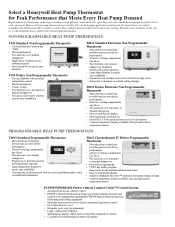
... heat/one cool; Y594 Deluxe Non-Programmable Thermostat • Proven reliability with optional outdoor temperature sensor. manual changeover eliminates unexpected system operation. • Large digital display for the installer and the homeowner. • Easy-to eliminate accidental setting changes. automatic or manual changeover. • Seven-day programming. • COPY key makes program- Honeywell heat pump thermostats...
... heat/one cool; Y594 Deluxe Non-Programmable Thermostat • Proven reliability with optional outdoor temperature sensor. manual changeover eliminates unexpected system operation. • Large digital display for the installer and the homeowner. • Easy-to eliminate accidental setting changes. automatic or manual changeover. • Seven-day programming. • COPY key makes program- Honeywell heat pump thermostats...
User Guide
Page 4
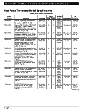
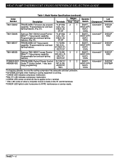
... Premier White™. Replaces Coleman/Evcon Y594G1377 (Fig. 21). Fixed anticipation. Manual heat HEAT-OFF- EM.HT., AUX. or cool AUX. Auto heat EM.HT., EM.HT. COOL 2 1 OFF- HEAT- HEAT PUMP THERMOSTAT CROSS REFERENCE/SELECTION GUIDE Heat Pump Thermostat Model Specifications Table 1. No auto fan in EM. Includes outdoor reset and fixed anticipation on stage 2 heat. for two-stage W2,W3,Y,G, heating and one -stage cooling...
... Premier White™. Replaces Coleman/Evcon Y594G1377 (Fig. 21). Fixed anticipation. Manual heat HEAT-OFF- EM.HT., AUX. or cool AUX. Auto heat EM.HT., EM.HT. COOL 2 1 OFF- HEAT- HEAT PUMP THERMOSTAT CROSS REFERENCE/SELECTION GUIDE Heat Pump Thermostat Model Specifications Table 1. No auto fan in EM. Includes outdoor reset and fixed anticipation on stage 2 heat. for two-stage W2,W3,Y,G, heating and one -stage cooling...
User Guide
Page 6
... Stages Systems Heat Cool Switch Changeover T8611G2002 TRADELINE®; OT,OT 1 EM.HT.- Automatica HEAT-OFF- Programmable fan and back W3,G,E,L, lighting features. AUTO- COOL ...HT.- COOL T8611G2028 Same as T8611M2017 except Premier Y1,Y2,W2, 3 White™, 7-day program capability. COOL T8611M2017 TRADELINE®; COOL T8611M2025 Same as T8611G2002 except Premier Y1,W1...COOL a In freezing climates, be sure the cooling compressor has adequate cold start protection. G,E,L,R,C, Programmable fan and back lighting O/B,X1,X2, features. (Fig. 31). HEAT PUMP THERMOSTAT...
... Stages Systems Heat Cool Switch Changeover T8611G2002 TRADELINE®; OT,OT 1 EM.HT.- Automatica HEAT-OFF- Programmable fan and back W3,G,E,L, lighting features. AUTO- COOL ...HT.- COOL T8611G2028 Same as T8611M2017 except Premier Y1,Y2,W2, 3 White™, 7-day program capability. COOL T8611M2017 TRADELINE®; COOL T8611M2025 Same as T8611G2002 except Premier Y1,W1...COOL a In freezing climates, be sure the cooling compressor has adequate cold start protection. G,E,L,R,C, Programmable fan and back lighting O/B,X1,X2, features. (Fig. 31). HEAT PUMP THERMOSTAT...
User Guide
Page 7
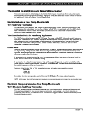
... a fairly large offset between the setpoint temperature and the room temperature. Select one -stage cool in the heater. Since heat pumps require thermostats with special features such as control of changeover valves, this section also explains some of the heat pump thermostats that Honeywell manufactures. Y594G models have automatic changeover; Accessories include tamper-resistant cover and locking...
... a fairly large offset between the setpoint temperature and the room temperature. Select one -stage cool in the heater. Since heat pumps require thermostats with special features such as control of changeover valves, this section also explains some of the heat pump thermostats that Honeywell manufactures. Y594G models have automatic changeover; Accessories include tamper-resistant cover and locking...
User Guide
Page 8
... multistage equipment is fixed; However, there is no jumper is a three-stage heat/two-stage cool thermostat used to control multistage heat pump equipment. The differential required between low-speed and high-speed in heat pump systems, using manual changeover. Using the T8611M on Two-Speed Heat Pump Compressor Equipment The T8611M is required. 70-6627 • 6 second...
... multistage equipment is fixed; However, there is no jumper is a three-stage heat/two-stage cool thermostat used to control multistage heat pump equipment. The differential required between low-speed and high-speed in heat pump systems, using manual changeover. Using the T8611M on Two-Speed Heat Pump Compressor Equipment The T8611M is required. 70-6627 • 6 second...

User Guide
Page 15
... makes on some heat pumps. The thermostat automatically changes between heat and cool modes as follows: Auto changeover-refers to HEAT (manual changeover) or by moving the system switch to the presence of the circuits from the transformer. HT.-HEAT-OFFCOOL switching). C1-Stage 1 Cooling. The reversing valve or relay is identified by function: H1-Stage 1 Heating. C3-Stage 3 Cooling. Manual changeover...
... makes on some heat pumps. The thermostat automatically changes between heat and cool modes as follows: Auto changeover-refers to HEAT (manual changeover) or by moving the system switch to the presence of the circuits from the transformer. HT.-HEAT-OFFCOOL switching). C1-Stage 1 Cooling. The reversing valve or relay is identified by function: H1-Stage 1 Heating. C3-Stage 3 Cooling. Manual changeover...

User Guide
Page 17
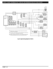
... (GREEN) E L EM. HEAT PUMP THERMOSTAT CROSS REFERENCE/SELECTION GUIDE Typical System Hookup Diagrams L1 L2 (HOT) RTD 1 1 ODT 1 H1 C1 FALL H1/C1 ANTICIPATOR FAN SWITCH AUTO ON G R EHR 1 RTD 2 ODT 2 EHR 2 RTD 3 FAN RELAY H2 ANTICIPATOR H2 FALL 2 EM. HT. RELAY SYSTEM MONITOR X LACO Y HEAT CHANGEOVER VALVE COMPRESSOR CONTACTOR O COOL CHANGEOVER VALVE CHP...
... (GREEN) E L EM. HEAT PUMP THERMOSTAT CROSS REFERENCE/SELECTION GUIDE Typical System Hookup Diagrams L1 L2 (HOT) RTD 1 1 ODT 1 H1 C1 FALL H1/C1 ANTICIPATOR FAN SWITCH AUTO ON G R EHR 1 RTD 2 ODT 2 EHR 2 RTD 3 FAN RELAY H2 ANTICIPATOR H2 FALL 2 EM. HT. RELAY SYSTEM MONITOR X LACO Y HEAT CHANGEOVER VALVE COMPRESSOR CONTACTOR O COOL CHANGEOVER VALVE CHP...
User Guide
Page 18
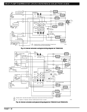
... and T841A1738. HT. HEAT LED (RED) W3 RELAY COOL CHANGEOVER RELAY G R E X AUX. HEAT RELAY B HEAT CHANGEOVER RELAY COMPRESSOR CONTACTOR Y Fig. 18. HEAT PUMP TH ERMOSTAT CROSS REFERENCE/SELECTION GUIDE 9 H1 C1 FALL 2 C ANTICIPATOR 3 H1/C ANTICIPATOR 5 FAN SWITCH AUTO ON G W U AUX. HEAT LED (GRN) W2 FAN RELAY EM. COMPRESSOR MONITOR R OUTDOOR THERMOSTAT X2 T OUTDOOR O THERMISTOR COOL CHANGEOVER RELAY COMPRESSOR...
... and T841A1738. HT. HEAT LED (RED) W3 RELAY COOL CHANGEOVER RELAY G R E X AUX. HEAT RELAY B HEAT CHANGEOVER RELAY COMPRESSOR CONTACTOR Y Fig. 18. HEAT PUMP TH ERMOSTAT CROSS REFERENCE/SELECTION GUIDE 9 H1 C1 FALL 2 C ANTICIPATOR 3 H1/C ANTICIPATOR 5 FAN SWITCH AUTO ON G W U AUX. HEAT LED (GRN) W2 FAN RELAY EM. COMPRESSOR MONITOR R OUTDOOR THERMOSTAT X2 T OUTDOOR O THERMISTOR COOL CHANGEOVER RELAY COMPRESSOR...
User Guide
Page 19
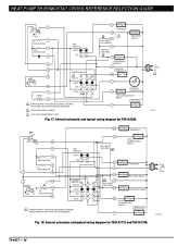
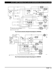
Internal schematic and typical wiring diagram for T841B1000. HEAT PUMP THERMOSTAT CROSS REFERENCE/SELECTION GUIDE H1/C1 ANTICIPATOR H1 C1 FALL FAN SWITCH AUTO ON W1 HEAT RELAY 1 W2 HEAT RELAY 2 B HEAT CHANGEOVER VALVE G FAN RELAY H2 ANTICIPATOR H2 FALL SYSTEM SWITCH HEAT OFF COOL 1 POWER SUPPLY. Internal schematic and typical wiring diagram for Y594G1161. HT. PROVIDE DISCONNECT...
Internal schematic and typical wiring diagram for T841B1000. HEAT PUMP THERMOSTAT CROSS REFERENCE/SELECTION GUIDE H1/C1 ANTICIPATOR H1 C1 FALL FAN SWITCH AUTO ON W1 HEAT RELAY 1 W2 HEAT RELAY 2 B HEAT CHANGEOVER VALVE G FAN RELAY H2 ANTICIPATOR H2 FALL SYSTEM SWITCH HEAT OFF COOL 1 POWER SUPPLY. Internal schematic and typical wiring diagram for Y594G1161. HT. PROVIDE DISCONNECT...
User Guide
Page 20
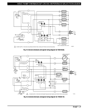
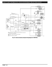
...W1 - COMPRESSOR CONTACTOR M8702 Fig. 21. Internal schematic and typical wiring diagram for Y594G1633. HEAT LED (GREEN) AUX. HT. LED (RED) X COOL CHANGEOVER VALVE O B W1 RELAY W1 HEAT CHANGEOVER VALVE 2 COMPRESSOR CONTACTOR Y1 1 POWER SUPPLY. REMOVE JUMPER WHEN W1 RELAY IS ...6 CHANGEOVER 8 (COOL) 9 RISE 10 C1 ANTICIPATOR C1 11 SYSTEM SWITCH OFF EM. LED (GREEN) X1 EM. Y1 JUMPER IS Y TERMINAL; HT. LED (RED) X AUX. PROVIDE DISCONNECT MEANS AND OVERLOAD PROTECTION AS REQUIRED. M8703 Fig. 22. HT. HEAT PUMP THERMOSTAT CROSS REFERENCE/SELECTION ...
...W1 - COMPRESSOR CONTACTOR M8702 Fig. 21. Internal schematic and typical wiring diagram for Y594G1633. HEAT LED (GREEN) AUX. HT. LED (RED) X COOL CHANGEOVER VALVE O B W1 RELAY W1 HEAT CHANGEOVER VALVE 2 COMPRESSOR CONTACTOR Y1 1 POWER SUPPLY. REMOVE JUMPER WHEN W1 RELAY IS ...6 CHANGEOVER 8 (COOL) 9 RISE 10 C1 ANTICIPATOR C1 11 SYSTEM SWITCH OFF EM. LED (GREEN) X1 EM. Y1 JUMPER IS Y TERMINAL; HT. LED (RED) X AUX. PROVIDE DISCONNECT MEANS AND OVERLOAD PROTECTION AS REQUIRED. M8703 Fig. 22. HT. HEAT PUMP THERMOSTAT CROSS REFERENCE/SELECTION ...
User Guide
Page 21
... REQUIRED. 2 FIELD REMOVABLE JUMPER. PROVIDE DISCONNECT MEANS AND OVERLOAD PROTECTION AS REQUIRED. HEAT PUMP THERMOSTAT CROSS REFERENCE/SELECTION GUIDE 1 2 H1 C1 FALL 3 4 H2 FALL 5 6 11 AUTO ON FAN SWITCH SYSTEM SWITCH EM. AUX. HT. HEAT RELAY W2 FAN RELAY G COOL CHANGEOVER VALVE O COOL E COMPRESSOR EM. Internal schematic and typical wiring diagram for Y594R1763. 2 H1 AND...
... REQUIRED. 2 FIELD REMOVABLE JUMPER. PROVIDE DISCONNECT MEANS AND OVERLOAD PROTECTION AS REQUIRED. HEAT PUMP THERMOSTAT CROSS REFERENCE/SELECTION GUIDE 1 2 H1 C1 FALL 3 4 H2 FALL 5 6 11 AUTO ON FAN SWITCH SYSTEM SWITCH EM. AUX. HT. HEAT RELAY W2 FAN RELAY G COOL CHANGEOVER VALVE O COOL E COMPRESSOR EM. Internal schematic and typical wiring diagram for Y594R1763. 2 H1 AND...
User Guide
Page 22
HT. HT. HT. HEAT OFF COOL 11 1 POWER SUPPLY. HT. LED (RED) AUX. LED (GRN) W2 AUX. RELAY X 3 X2 HEAT CHANGEOVER VALVE B W1 RELAY W1 2 COMPRESSOR CONTACTOR Y L1 (HOT) L2 1 M8713 Fig. 25. Internal schematic and typical wiring diagram for Y594R1425. 70-6627 • 20 HEAT PUMP THERMOSTAT CROSS REFERENCE/SELECTION GUIDE W3 W3 RELAY H1...
HT. HT. HT. HEAT OFF COOL 11 1 POWER SUPPLY. HT. LED (RED) AUX. LED (GRN) W2 AUX. RELAY X 3 X2 HEAT CHANGEOVER VALVE B W1 RELAY W1 2 COMPRESSOR CONTACTOR Y L1 (HOT) L2 1 M8713 Fig. 25. Internal schematic and typical wiring diagram for Y594R1425. 70-6627 • 20 HEAT PUMP THERMOSTAT CROSS REFERENCE/SELECTION GUIDE W3 W3 RELAY H1...
User Guide
Page 25
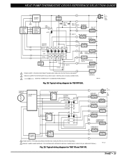
.... 70-6627 • 23 HEAT OFF COOL HIGH LIMIT HIGH LIMIT EM. HT. RELAY E STAGE 1 HEAT RELAY W1 FAN RELAY G COOL 1 HEAT 1 O 2 COOL CHANGEOVER VALVE B HEAT CHANGEOVER VALVE Y1 COMPRESSOR CONTACTOR P 1 POWER SUPPLY. M11333 Fig. 29. L1 (HOT) L2 1 THERMISTOR SENSOR THERMOSTAT LOGIC STAGE 2 RELAY STAGE 1 RELAY SYSTEM SWITCH EM. HEAT PUMP THERMOSTAT CROSS REFERENCE/SELECTION GUIDE POWER SUPPLY 3 THERMOSTAT LOGIC CIRCUIT SUBBASE LOGIC...
.... 70-6627 • 23 HEAT OFF COOL HIGH LIMIT HIGH LIMIT EM. HT. RELAY E STAGE 1 HEAT RELAY W1 FAN RELAY G COOL 1 HEAT 1 O 2 COOL CHANGEOVER VALVE B HEAT CHANGEOVER VALVE Y1 COMPRESSOR CONTACTOR P 1 POWER SUPPLY. M11333 Fig. 29. L1 (HOT) L2 1 THERMISTOR SENSOR THERMOSTAT LOGIC STAGE 2 RELAY STAGE 1 RELAY SYSTEM SWITCH EM. HEAT PUMP THERMOSTAT CROSS REFERENCE/SELECTION GUIDE POWER SUPPLY 3 THERMOSTAT LOGIC CIRCUIT SUBBASE LOGIC...
User Guide
Page 26
... REQUIRED. 2 O/B IS FIELD CONFIGURABLE TO SELECT ENERGIZED IN HEATING OR COOLING. (DEFAULT IS ENERGIZED IN HEATING). 3 REMOVE JUMPER, WHEN SUPPLIED, FOR SYSTEMS WITH SEPARATE HEATING COMPRESSOR CONTACTOR (W1 SEPARATE FROM Y1). CHECK LED (RED) L OT OT Fig. 30. HEAT PUMP THERMOSTAT CROSS REFERENCE/SELECTION GUIDE L1 1 (HOT) L2 R THERMOSTAT LOGIC POWER SUPPLY W2 W1 E Y1 G O/B W2 W1...
... REQUIRED. 2 O/B IS FIELD CONFIGURABLE TO SELECT ENERGIZED IN HEATING OR COOLING. (DEFAULT IS ENERGIZED IN HEATING). 3 REMOVE JUMPER, WHEN SUPPLIED, FOR SYSTEMS WITH SEPARATE HEATING COMPRESSOR CONTACTOR (W1 SEPARATE FROM Y1). CHECK LED (RED) L OT OT Fig. 30. HEAT PUMP THERMOSTAT CROSS REFERENCE/SELECTION GUIDE L1 1 (HOT) L2 R THERMOSTAT LOGIC POWER SUPPLY W2 W1 E Y1 G O/B W2 W1...
User Guide
Page 28
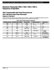
...) Sequences of Operation T8011 Programmable Heat Pump Thermostat and T8411 Electronic Heat Pump Thermostat Sequence of operations for Action Energize Terminals Cool Cool None Cooling O O, Y, G Display Icons None Auto Auto Heat Heat None Stage 1 Heat B B, W1, G None Auto Auto Auto Heat Em. Table 2 shows the sequence of Operation The Fan, Heat and Cool outputs are relay controlled. Ht. Stage 2 Heat None Stage 1 Heat B, W1, W2, G L L, E, G , Aux Ht indicator...
...) Sequences of Operation T8011 Programmable Heat Pump Thermostat and T8411 Electronic Heat Pump Thermostat Sequence of operations for Action Energize Terminals Cool Cool None Cooling O O, Y, G Display Icons None Auto Auto Heat Heat None Stage 1 Heat B B, W1, G None Auto Auto Auto Heat Em. Table 2 shows the sequence of Operation The Fan, Heat and Cool outputs are relay controlled. Ht. Stage 2 Heat None Stage 1 Heat B, W1, W2, G L L, E, G , Aux Ht indicator...
User Guide
Page 31
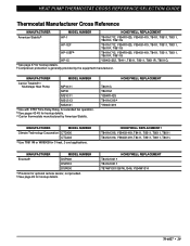
...b See page 49 for hookup details. c Carrier thermostats manufactured by the equipment manufacturer. HEAT PUMP THERMOSTAT CROSS REFERENCE/SELECTION GUIDE Thermostat Manufacturer Cross Reference MANUFACTURER MODEL NUMBER HONEYWELL REPLACEMENT American Stabilisa HP-1 T841A1712, Y594R1425, Y594G1419, ..., T8511, T8011, T8611, MANUFACTURER MODEL NUMBER Enerstatb DSP400 DSP410 DSP600 a Provision for 3 heat, 2 cool applications. HONEYWELL REPLACEMENT T8611G T8611M Y594R1425 T841A1316a Y594G1419 MANUFACTURER MODEL NUMBER Climate Technology Corporation CTC400 CTC403 a Use ...
...b See page 49 for hookup details. c Carrier thermostats manufactured by the equipment manufacturer. HEAT PUMP THERMOSTAT CROSS REFERENCE/SELECTION GUIDE Thermostat Manufacturer Cross Reference MANUFACTURER MODEL NUMBER HONEYWELL REPLACEMENT American Stabilisa HP-1 T841A1712, Y594R1425, Y594G1419, ..., T8511, T8011, T8611, MANUFACTURER MODEL NUMBER Enerstatb DSP400 DSP410 DSP600 a Provision for 3 heat, 2 cool applications. HONEYWELL REPLACEMENT T8611G T8611M Y594R1425 T841A1316a Y594G1419 MANUFACTURER MODEL NUMBER Climate Technology Corporation CTC400 CTC403 a Use ...
User Guide
Page 35
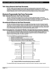
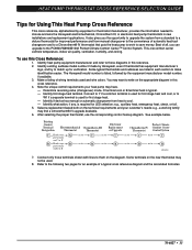
It also gives you can upgrade to the following two pages for first stage heat and cool, or to choose and wire the Honeywell electromechanical, Chronotherm III, or electronic heat pump thermostats in this Cross Reference: 1. Identify existing subbase model number if made by Honeywell, even if thermostat has equipment manufacturer's logo, and try to save money. You may...
It also gives you can upgrade to the following two pages for first stage heat and cool, or to choose and wire the Honeywell electromechanical, Chronotherm III, or electronic heat pump thermostats in this Cross Reference: 1. Identify existing subbase model number if made by Honeywell, even if thermostat has equipment manufacturer's logo, and try to save money. You may...
User Guide
Page 37
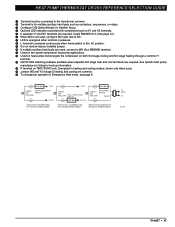
... when terminal is powered. º L terminal is powered continuously when thermostat is in Em. HEAT PUMP THERMOSTAT CROSS REFERENCE/SELECTION GUIDE ³ Terminal must be connected to the transformer common. · Terminal is for hookup information. ƹ P terminal on both first stage cooling and first stage heating through a common Y terminal. Ƹ Q674F1022 switching subbase available when separate...
... when terminal is powered. º L terminal is powered continuously when thermostat is in Em. HEAT PUMP THERMOSTAT CROSS REFERENCE/SELECTION GUIDE ³ Terminal must be connected to the transformer common. · Terminal is for hookup information. ƹ P terminal on both first stage cooling and first stage heating through a common Y terminal. Ƹ Q674F1022 switching subbase available when separate...
User Guide
Page 46
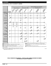
Heat 2nd Stage Compressor - ´ Y1 W1 - - - - Heat E 2nd Stg. M13149 TYPICAL THERMOSTATS AND SUBBASES - LED Indication - G G B B O ² X2 ² E Y2 ³ - Heat C/O Valve O Cool System Monitor/ L System Defrost EM. O µ L E Y2 ³ X1 X2 » G ¿ O/B ¿ O/B ¾ L E - - For system monitor LED indication, connect L to X2. ¶ Both first stage heat and cool are connected to Y or Y1/W1...
Heat 2nd Stage Compressor - ´ Y1 W1 - - - - Heat E 2nd Stg. M13149 TYPICAL THERMOSTATS AND SUBBASES - LED Indication - G G B B O ² X2 ² E Y2 ³ - Heat C/O Valve O Cool System Monitor/ L System Defrost EM. O µ L E Y2 ³ X1 X2 » G ¿ O/B ¿ O/B ¾ L E - - For system monitor LED indication, connect L to X2. ¶ Both first stage heat and cool are connected to Y or Y1/W1...
User Guide
Page 62
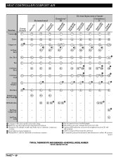
... X2 - - position. M13217 TYPICAL THERMOSTATS AND SUBBASES-HONEYWELL MODEL NUMBER T874G1469/Q674F1345 70-6627 • 60 W2 W2 W2 G G G ³ or B B O/B B ³ or O O O/B O W2 G ³ or B O/B ³ or O O/B ¶ Aux. E E E - - - º - Heat Aux. G ³ O/B ³ O/B µ ¾ µ ¾ ¾ L L L L L E E E W3 W3 - Heat W2 W2 Fan G G C/O Valve - X1 X2 - ¶ 2nd Stage - - - - - - - - - Cool - - - ³ Configure O/B (select...
... X2 - - position. M13217 TYPICAL THERMOSTATS AND SUBBASES-HONEYWELL MODEL NUMBER T874G1469/Q674F1345 70-6627 • 60 W2 W2 W2 G G G ³ or B B O/B B ³ or O O O/B O W2 G ³ or B O/B ³ or O O/B ¶ Aux. E E E - - - º - Heat Aux. G ³ O/B ³ O/B µ ¾ µ ¾ ¾ L L L L L E E E W3 W3 - Heat W2 W2 Fan G G C/O Valve - X1 X2 - ¶ 2nd Stage - - - - - - - - - Cool - - - ³ Configure O/B (select...


