
Owner's Manual
Page 1
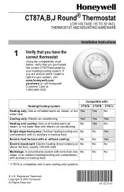
... right for your system, visit www.honeywell.com/ yourhome or call Honeywell Customer Care at 1-800-468-1502. Registered Trademark Copyright © 2002 Honeywell All Rights Reserved 69-0274-6 No ...compatibility chart below, verify that you are unsure which model is compatible with 2-wire cooling-only systems. ® U.S. If you purchased the correct CT87Thermostat for your heating/...cooling system. Installation Instructions Compatible with: Heating/Cooling system CT87A CT87B CT87J Heating only: Gas or oil fueled warm air, steam, or hot Yes...
... right for your system, visit www.honeywell.com/ yourhome or call Honeywell Customer Care at 1-800-468-1502. Registered Trademark Copyright © 2002 Honeywell All Rights Reserved 69-0274-6 No ...compatibility chart below, verify that you are unsure which model is compatible with 2-wire cooling-only systems. ® U.S. If you purchased the correct CT87Thermostat for your heating/...cooling system. Installation Instructions Compatible with: Heating/Cooling system CT87A CT87B CT87J Heating only: Gas or oil fueled warm air, steam, or hot Yes...
Owner's Manual
Page 2
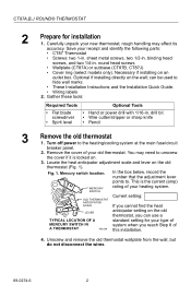
...rough handling may need to the heating/cooling system at the main fuse/circuit breaker panel. 2. round head screws • Wallplate (CT87A) or subbase (CT87B, CT87J) • Cover ring (select models only). You may affect its accuracy. Mercury switch location. sheet metal screws, two 1/2-in . can use... setting: If you cannot find the heat LEVER anticipator setting on the wall; Carefully unpack your old thermostat. drill bit • Wire cutter/stripper or sharp knife • Pencil 3 Remove the old thermostat 1. In the box below, record the number that the ...
...rough handling may need to the heating/cooling system at the main fuse/circuit breaker panel. 2. round head screws • Wallplate (CT87A) or subbase (CT87B, CT87J) • Cover ring (select models only). You may affect its accuracy. Mercury switch location. sheet metal screws, two 1/2-in . can use... setting: If you cannot find the heat LEVER anticipator setting on the wall; Carefully unpack your old thermostat. drill bit • Wire cutter/stripper or sharp knife • Pencil 3 Remove the old thermostat 1. In the box below, record the number that the ...
Owner's Manual
Page 3
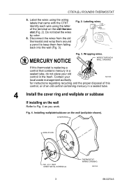
...If this control, or of an old control containing mercury in the trash. Do not label the wires by color. 6. M19086 MERCURY NOTICE Fig. 3. Identify each wire using the wiring labels that contains mercury in a sealed tube, do not place your old control in a sealed ...pencil to Fig. 4 as you work. Installing wallplate/subbase on the old thermo- CT87A,B,J ROUND® THERMOSTAT 5. Fig. 4. Labeling wires. Contact your M20133 local waste management authority for instructions regarding recycling and the proper disposal of the terminal on the wall (wallplate shown)....
...If this control, or of an old control containing mercury in the trash. Do not label the wires by color. 6. M19086 MERCURY NOTICE Fig. 3. Identify each wire using the wiring labels that contains mercury in a sealed tube, do not place your old control in a sealed ...pencil to Fig. 4 as you work. Installing wallplate/subbase on the old thermo- CT87A,B,J ROUND® THERMOSTAT 5. Fig. 4. Labeling wires. Contact your M20133 local waste management authority for instructions regarding recycling and the proper disposal of the terminal on the wall (wallplate shown)....
Owner's Manual
Page 4
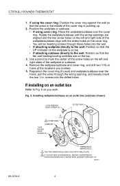
... Installing wallplate/subbase on the left and right side of the wallplate or subbase. 4. CT87A,B,J ROUND® THERMOSTAT 1. ROUND HEAD SCREW (2) A THERMOSTAT WIRING HOLE 1 THE TWO INNER HOLES ARE USED WITH WALLPLATE. 2 IF OUTLET BOX IS HORIZONTAL, MOUNT COVER RING IN POSITION SHOWN, BUT FASTEN WITH SCREWS ...THROUGH "A". holes at the locations you work. You will be inserting screws through the wiring opening, and loosely insert the two 1-in . Remove the wallplate/subbase and cover ring, and drill two 1/16-in . If installing ...
... Installing wallplate/subbase on the left and right side of the wallplate or subbase. 4. CT87A,B,J ROUND® THERMOSTAT 1. ROUND HEAD SCREW (2) A THERMOSTAT WIRING HOLE 1 THE TWO INNER HOLES ARE USED WITH WALLPLATE. 2 IF OUTLET BOX IS HORIZONTAL, MOUNT COVER RING IN POSITION SHOWN, BUT FASTEN WITH SCREWS ...THROUGH "A". holes at the locations you work. You will be inserting screws through the wiring opening, and loosely insert the two 1-in . Remove the wallplate/subbase and cover ring, and drill two 1/16-in . If installing ...
Owner's Manual
Page 5
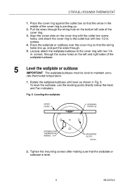
..., through . 5. Leveling the wallplate. SPIRIT LEVEL LEVELING POSTS (2) OPENING FOR THERMOSTAT WIRING MOUNTING SLOTS M3319A 2. Place the wallplate or subbase over the cover ring so that the wallplate or subbase is pointing up , and pull the wires through the screw holes on the left side of the cover ring. 3. Pull... the wires through the wiring hole on the cover ring with the outlet box screw holes, and attach the cover ...
..., through . 5. Leveling the wallplate. SPIRIT LEVEL LEVELING POSTS (2) OPENING FOR THERMOSTAT WIRING MOUNTING SLOTS M3319A 2. Place the wallplate or subbase over the cover ring so that the wallplate or subbase is pointing up , and pull the wires through the screw holes on the left side of the cover ring. 3. Pull... the wires through the wiring hole on the cover ring with the outlet box screw holes, and attach the cover ...
Owner's Manual
Page 6
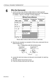
...-reference table below to fit the wires underneath the terminal screws (Fig. 7). Fitting wires under the terminal screws. See Fig. 8 through 13 wiring diagrams. Wiring Cross-reference Wire Label R, RH, 4, V Rc, R W, W1, H Y, Y1, M G, F B O See Fig. 13 Connect to CT87A R W Y See Fig. 9 Connect to Connect to CT87B CT87J RH R Rc W W Y Y G G B* O* P *Never attach wires to both the B and O terminals...
...-reference table below to fit the wires underneath the terminal screws (Fig. 7). Fitting wires under the terminal screws. See Fig. 8 through 13 wiring diagrams. Wiring Cross-reference Wire Label R, RH, 4, V Rc, R W, W1, H Y, Y1, M G, F B O See Fig. 13 Connect to CT87A R W Y See Fig. 9 Connect to Connect to CT87B CT87J RH R Rc W W Y Y G G B* O* P *Never attach wires to both the B and O terminals...
Owner's Manual
Page 7
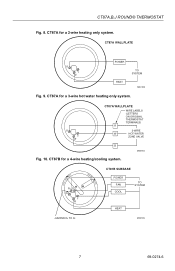
R Y W CT87A WALLPLATE WIRE LABELS (LETTERS ON ORIGINAL THERMOSTAT TERMINALS) R 3-WIRE W HOT WATER ZONE VALVE B M20184 Fig. 10. CT87A,B,J ROUND® THERMOSTAT Fig. 8. CT87A for a 4-wire heating/cooling system. CT87B for a 2-wire heating only system. CT87A WALLPLATE R Y W POWER HEAT TO SYSTEM M20183 Fig. 9. COOL • OFF • HEAT FAN ON RH G RC Y W AUTO • CT87B SUBBASE POWER FAN COOL TO SYSTEM HEAT JUMPER RH TO RC M20185 7 69-0274-6 CT87A for a 3-wire hot water heating only system.
R Y W CT87A WALLPLATE WIRE LABELS (LETTERS ON ORIGINAL THERMOSTAT TERMINALS) R 3-WIRE W HOT WATER ZONE VALVE B M20184 Fig. 10. CT87A,B,J ROUND® THERMOSTAT Fig. 8. CT87A for a 4-wire heating/cooling system. CT87B for a 2-wire heating only system. CT87A WALLPLATE R Y W POWER HEAT TO SYSTEM M20183 Fig. 9. COOL • OFF • HEAT FAN ON RH G RC Y W AUTO • CT87B SUBBASE POWER FAN COOL TO SYSTEM HEAT JUMPER RH TO RC M20185 7 69-0274-6 CT87A for a 3-wire hot water heating only system.
Owner's Manual
Page 8
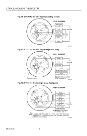
...REVERSING VALVE HEAT REVERSING VALVE DO NOT ATTACH WIRES TO BOTH B AND O M20186 Fig. 13. M20228 69-0274-6 8 CT87J for a 4-wire single stage heat pump. CT87A,B,J ROUND® THERMOSTAT Fig. 11. CT87J for 4-wire single stage heat pump. CT87B for a 5-wire heating/cooling system. CT87J SUBBASE HEAT FAN... PUMP COMPRESSOR DO NOT ATTACH WIRES TO BOTH B AND O 1 IF WIRES ARE ATTACHED TO Y OR W, AND P ON YOUR OLD THERMOSTAT, CONTACT YOUR LOCAL CONTRACTOR FOR FURTHER ASSISTANCE. COOL • OFF • HEAT FAN ON RH G RC Y W AUTO • CT87B SUBBASE HEATING POWER FAN TO ...
...REVERSING VALVE HEAT REVERSING VALVE DO NOT ATTACH WIRES TO BOTH B AND O M20186 Fig. 13. M20228 69-0274-6 8 CT87J for a 4-wire single stage heat pump. CT87A,B,J ROUND® THERMOSTAT Fig. 11. CT87J for 4-wire single stage heat pump. CT87B for a 5-wire heating/cooling system. CT87J SUBBASE HEAT FAN... PUMP COMPRESSOR DO NOT ATTACH WIRES TO BOTH B AND O 1 IF WIRES ARE ATTACHED TO Y OR W, AND P ON YOUR OLD THERMOSTAT, CONTACT YOUR LOCAL CONTRACTOR FOR FURTHER ASSISTANCE. COOL • OFF • HEAT FAN ON RH G RC Y W AUTO • CT87B SUBBASE HEATING POWER FAN TO ...


