
Owner's Manual
Page 1
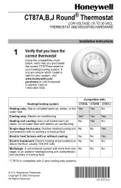
... thermostat Using the compatibility chart below, verify that you are unsure which model is compatible with 2-wire cooling-only systems. ® U.S. No Yes Electric heat furnace with or without cooling: No No Yes Electric baseboard: Electric heating strips located just No above the floor, usually 120-240 volts No No Multistage: A conventional system with more than one No stage, or an outdoor heating/cooling unit (compressor) with no auxiliary...
... thermostat Using the compatibility chart below, verify that you are unsure which model is compatible with 2-wire cooling-only systems. ® U.S. No Yes Electric heat furnace with or without cooling: No No Yes Electric baseboard: Electric heating strips located just No above the floor, usually 120-240 volts No No Multistage: A conventional system with more than one No stage, or an outdoor heating/cooling unit (compressor) with no auxiliary...
Owner's Manual
Page 2
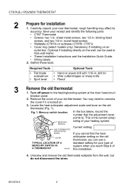
... old thermostat (Fig. 1). Unscrew and remove the old thermostat wallplate from the wall, but do not disconnect the wires. 69-0274-6 2 Locate the heat anticipator adjustment scale and lever on . 3. Mercury switch location. drill bit • Wire cutter/stripper or sharp knife • Pencil 3 Remove the old thermostat 1. You may affect its accuracy. can use a TYPICAL LOCATION OF A standard setting for installation 1. rough handling may need to unscrew the cover...
... old thermostat (Fig. 1). Unscrew and remove the old thermostat wallplate from the wall, but do not disconnect the wires. 69-0274-6 2 Locate the heat anticipator adjustment scale and lever on . 3. Mercury switch location. drill bit • Wire cutter/stripper or sharp knife • Pencil 3 Remove the old thermostat 1. You may affect its accuracy. can use a TYPICAL LOCATION OF A standard setting for installation 1. rough handling may need to unscrew the cover...
Owner's Manual
Page 3
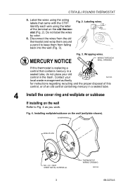
Label the wires using the letter of an old control containing mercury in the trash. WIRES THROUGH WALL OPENING If this thermostat is replacing a control that came with the CT87. stat (Fig. 2). Do not label the wires by color. 6. Wrapping wires. Installing wallplate/subbase on the wall Refer to keep them from falling back into the wall (Fig. 3). Fig. 2. COVER RING WALLPLATE NO. 4 X 1 INCH SHEET METAL SCREWS (2) 3 THERMOSTAT WIRING OPENING...
Label the wires using the letter of an old control containing mercury in the trash. WIRES THROUGH WALL OPENING If this thermostat is replacing a control that came with the CT87. stat (Fig. 2). Do not label the wires by color. 6. Wrapping wires. Installing wallplate/subbase on the wall Refer to keep them from falling back into the wall (Fig. 3). Fig. 2. COVER RING WALLPLATE NO. 4 X 1 INCH SHEET METAL SCREWS (2) 3 THERMOSTAT WIRING OPENING...
Owner's Manual
Page 4
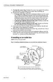
You will be inserting screws through the wiring opening, and loosely insert the two 1-in. If installing on an outlet box Refer to the wall: Position so that the fan and heating/cooling switches are aligned and the two screw holes on the left and right sides of the cover ring is on the top. 3. BINDING HEAD SCREW (2) OUTLET...
You will be inserting screws through the wiring opening, and loosely insert the two 1-in. If installing on an outlet box Refer to the wall: Position so that the fan and heating/cooling switches are aligned and the two screw holes on the left and right sides of the cover ring is on the top. 3. BINDING HEAD SCREW (2) OUTLET...
Owner's Manual
Page 5
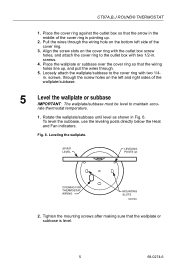
...the outlet box with two 1/4in. CT87A,B,J ROUND® THERMOSTAT 1. screws, through the wiring hole on the cover ring with the outlet box screw holes, and attach the cover ring to maintain accu- Fig. 6. screws. ...cover ring so that the wallplate or subbase is pointing up , and pull the wires through. 5. Align the screw slots on the bottom left and right sides of the cover ring. 3. To level the subbase, use the leveling posts directly below the Heat and Fan indicators. Loosely attach the wallplate/subbase to the cover ring with two 1/2-in. rate thermostat temperature...
...the outlet box with two 1/4in. CT87A,B,J ROUND® THERMOSTAT 1. screws, through the wiring hole on the cover ring with the outlet box screw holes, and attach the cover ring to maintain accu- Fig. 6. screws. ...cover ring so that the wallplate or subbase is pointing up , and pull the wires through. 5. Align the screw slots on the bottom left and right sides of the cover ring. 3. To level the subbase, use the leveling posts directly below the Heat and Fan indicators. Loosely attach the wallplate/subbase to the cover ring with two 1/2-in. rate thermostat temperature...
Owner's Manual
Page 6
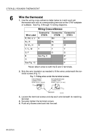
... the wire insulation as needed to both the B and O terminals. 2. Fig. 7. CT87A,B,J ROUND® THERMOSTAT 6 Wire the thermostat 1. FOR STRAIGHT CONNECTION- STRIP 7/16 in . [8 mm] FOR WRAPAROUND CONNECTION- See Fig. 8 through 13 wiring diagrams. Wiring Cross-reference Wire Label R, RH, 4, V Rc, R W, W1, H Y, Y1, M G, F B O See Fig. 13 Connect to CT87A R W Y See Fig. 9 Connect to Connect to CT87B CT87J RH R Rc W W Y Y G G B* O* P *Never attach wires to fit the wires underneath the terminal screws...
... the wire insulation as needed to both the B and O terminals. 2. Fig. 7. CT87A,B,J ROUND® THERMOSTAT 6 Wire the thermostat 1. FOR STRAIGHT CONNECTION- STRIP 7/16 in . [8 mm] FOR WRAPAROUND CONNECTION- See Fig. 8 through 13 wiring diagrams. Wiring Cross-reference Wire Label R, RH, 4, V Rc, R W, W1, H Y, Y1, M G, F B O See Fig. 13 Connect to CT87A R W Y See Fig. 9 Connect to Connect to CT87B CT87J RH R Rc W W Y Y G G B* O* P *Never attach wires to fit the wires underneath the terminal screws...
Owner's Manual
Page 7
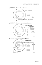
R Y W CT87A WALLPLATE WIRE LABELS (LETTERS ON ORIGINAL THERMOSTAT TERMINALS) R 3-WIRE W HOT WATER ZONE VALVE B M20184 Fig. 10. CT87B for a 3-wire hot water heating only system. CT87A for a 4-wire heating/cooling system. CT87A WALLPLATE R Y W POWER HEAT TO SYSTEM M20183 Fig. 9. CT87A for a 2-wire heating only system. COOL • OFF • HEAT FAN ON RH G RC Y W AUTO • CT87B SUBBASE POWER FAN COOL TO SYSTEM HEAT JUMPER RH TO RC M20185 7 69-0274-6 CT87A,B,J ROUND® THERMOSTAT Fig. 8.
R Y W CT87A WALLPLATE WIRE LABELS (LETTERS ON ORIGINAL THERMOSTAT TERMINALS) R 3-WIRE W HOT WATER ZONE VALVE B M20184 Fig. 10. CT87B for a 3-wire hot water heating only system. CT87A for a 4-wire heating/cooling system. CT87A WALLPLATE R Y W POWER HEAT TO SYSTEM M20183 Fig. 9. CT87A for a 2-wire heating only system. COOL • OFF • HEAT FAN ON RH G RC Y W AUTO • CT87B SUBBASE POWER FAN COOL TO SYSTEM HEAT JUMPER RH TO RC M20185 7 69-0274-6 CT87A,B,J ROUND® THERMOSTAT Fig. 8.
Owner's Manual
Page 8
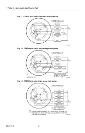
... P R B O HEAT REVERSING VALVE COOL REVERSING VALVE TO SYSTEM HEAT PUMP COMPRESSOR DO NOT ATTACH WIRES TO BOTH B AND O 1 IF WIRES ARE ATTACHED TO Y OR W, AND P ON YOUR OLD THERMOSTAT, CONTACT YOUR LOCAL CONTRACTOR FOR FURTHER ASSISTANCE. M20228 69-0274-6 8 CT87J for a 4-wire single stage heat pump. COOL • OFF • HEAT FAN ON RH G RC Y W AUTO • CT87B SUBBASE HEATING POWER FAN TO SYSTEM COOLING POWER TO SYSTEM COOL HEAT Fig. 12. CT87B for a 5-wire heating/cooling system. CT87A,B,J ROUND...
... P R B O HEAT REVERSING VALVE COOL REVERSING VALVE TO SYSTEM HEAT PUMP COMPRESSOR DO NOT ATTACH WIRES TO BOTH B AND O 1 IF WIRES ARE ATTACHED TO Y OR W, AND P ON YOUR OLD THERMOSTAT, CONTACT YOUR LOCAL CONTRACTOR FOR FURTHER ASSISTANCE. M20228 69-0274-6 8 CT87J for a 4-wire single stage heat pump. COOL • OFF • HEAT FAN ON RH G RC Y W AUTO • CT87B SUBBASE HEATING POWER FAN TO SYSTEM COOLING POWER TO SYSTEM COOL HEAT Fig. 12. CT87B for a 5-wire heating/cooling system. CT87A,B,J ROUND...
Owner's Manual
Page 9
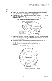
... SCREWS (3) M20227 9 69-0274-6 IMPORTANT: This prevents the thermostat from being damaged. HEAT ANTICIPATOR INDICATOR 1.2 .6 .5 .4 .3 .2 HOLE SUITABLE FOR PENCIL POINT TO MOVE INDICATOR .15 SCALE .12 .10 M20226 3. NOTE: These screws complete the installation of the thermostat. CT87A,B,J ROUND® THERMOSTAT 7 Mount the thermostat 1. Fig. 14. Pull off the thermostat cover and discard the red plastic insert that the three captive mounting screws...
... SCREWS (3) M20227 9 69-0274-6 IMPORTANT: This prevents the thermostat from being damaged. HEAT ANTICIPATOR INDICATOR 1.2 .6 .5 .4 .3 .2 HOLE SUITABLE FOR PENCIL POINT TO MOVE INDICATOR .15 SCALE .12 .10 M20226 3. NOTE: These screws complete the installation of the thermostat. CT87A,B,J ROUND® THERMOSTAT 7 Mount the thermostat 1. Fig. 14. Pull off the thermostat cover and discard the red plastic insert that the three captive mounting screws...
Owner's Manual
Page 10
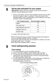
... before the set temperature, move the heat anticipator pointer to maintain accurate temperature control. 1. Snap on the old thermostat, use the setting for your system IMPORTANT: Setting the heat anticipator allows the thermostat to the number that you could not find the anticipator setting on the thermostat cover. SETTING SCALE 69-0274-6 THERMOMETER 10 M9656 The heating system should stop. Your heating system: Steam Hot water heat High-efficiency warm air Standard warm air Electric heat Heat anticipator setting: 1.2 0.8 0.8 0.4 0.3 2. Using a pencil...
... before the set temperature, move the heat anticipator pointer to maintain accurate temperature control. 1. Snap on the old thermostat, use the setting for your system IMPORTANT: Setting the heat anticipator allows the thermostat to the number that you could not find the anticipator setting on the thermostat cover. SETTING SCALE 69-0274-6 THERMOMETER 10 M9656 The heating system should stop. Your heating system: Steam Hot water heat High-efficiency warm air Standard warm air Electric heat Heat anticipator setting: 1.2 0.8 0.8 0.4 0.3 2. Using a pencil...
Owner's Manual
Page 11
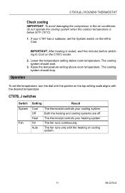
...,B,J ROUND® THERMOSTAT Check cooling IMPORTANT: To avoid damaging the compressor in the air conditioner, do not operate the cooling system when the outdoor temperature is tested, wait five minutes before switching to Cool. IMPORTANT: After heating is below room temperature. Lower the temperature setting below 50°F (10°C). 1. The cooling system should start. 3. The fan runs continuously. Operation To set the System switch on the left to Cool on the top setting...
...,B,J ROUND® THERMOSTAT Check cooling IMPORTANT: To avoid damaging the compressor in the air conditioner, do not operate the cooling system when the outdoor temperature is tested, wait five minutes before switching to Cool. IMPORTANT: After heating is below room temperature. Lower the temperature setting below 50°F (10°C). 1. The cooling system should start. 3. The fan runs continuously. Operation To set the System switch on the left to Cool on the top setting...
Owner's Manual
Page 12
... This warranty does not cover removal or reinstallation costs. THE DURATION OF ANY IMPLIED WARRANTIES, INCLUDING THE WARRANTIES OF MERCHANTABILITY AND FITNESS FOR A PARTICULAR PURPOSE, IS HEREBY LIMITED TO THE ONE YEAR DURATION OF THIS WARRANTY. CT87A,B,J ROUND® THERMOSTAT Limited One-Year Warranty Honeywell warrants this product, excluding battery, to be to repair or replace the product within a reasonable period of time. on...
... This warranty does not cover removal or reinstallation costs. THE DURATION OF ANY IMPLIED WARRANTIES, INCLUDING THE WARRANTIES OF MERCHANTABILITY AND FITNESS FOR A PARTICULAR PURPOSE, IS HEREBY LIMITED TO THE ONE YEAR DURATION OF THIS WARRANTY. CT87A,B,J ROUND® THERMOSTAT Limited One-Year Warranty Honeywell warrants this product, excluding battery, to be to repair or replace the product within a reasonable period of time. on...

