

Owner's Manual
Page 1
... ...17 Step 12. Table of Contents Step 1. Set Fan Operation Switch ...9 Step 7. Set the Clock ...14 Step 10. Programming ...14 Step 11. Remove Old Thermostat ...5 Step 3. Registered Trademark Copyright © 2004 Honeywell International Inc. Wire Wallplate Terminals ...7 Step 5. All Rights Reserved 69-1532-2 Honeywell CT8602 PROGRAMMABLE THERMOSTAT Seven Day Programmable Heat and/or Cool...
... ...17 Step 12. Table of Contents Step 1. Set Fan Operation Switch ...9 Step 7. Set the Clock ...14 Step 10. Programming ...14 Step 11. Remove Old Thermostat ...5 Step 3. Registered Trademark Copyright © 2004 Honeywell International Inc. Wire Wallplate Terminals ...7 Step 5. All Rights Reserved 69-1532-2 Honeywell CT8602 PROGRAMMABLE THERMOSTAT Seven Day Programmable Heat and/or Cool...

Owner's Manual
Page 3
... Current Day/Time Hold Temp Day Daylight Time Time Wake Heat/Cool Settings Copy Set Program Leave Return Sleep Heat Off Cool System On Auto Fan COPY ONE PROGRAMMED DAY TO ANOTHER DAY DECREASE TIME SETTING OR SCROLL BACKWARD THROUGH INSTALLER SETUP AND SYSTEM TEST INCREASE TEMPERATURE SETTING OR SCROLL FORWARD... TEMPERATURE SETTING OR SCROLL BACKWARD THROUGH INSTALLER SETUP OPTIONS DISPLAY INFORMATION SUCH AS PRESENT SETTINGS AND OUTDOOR TEMPERATURE SET SLEEP TIMES AND SETPOINTS SYSTEM SWITCH FAN SWITCH CHANGE BETWEEN HEATING AND COOLING SETPOINTS M14880 3 69-1532-2
... Current Day/Time Hold Temp Day Daylight Time Time Wake Heat/Cool Settings Copy Set Program Leave Return Sleep Heat Off Cool System On Auto Fan COPY ONE PROGRAMMED DAY TO ANOTHER DAY DECREASE TIME SETTING OR SCROLL BACKWARD THROUGH INSTALLER SETUP AND SYSTEM TEST INCREASE TEMPERATURE SETTING OR SCROLL FORWARD... TEMPERATURE SETTING OR SCROLL BACKWARD THROUGH INSTALLER SETUP OPTIONS DISPLAY INFORMATION SUCH AS PRESENT SETTINGS AND OUTDOOR TEMPERATURE SET SLEEP TIMES AND SETPOINTS SYSTEM SWITCH FAN SWITCH CHANGE BETWEEN HEATING AND COOLING SETPOINTS M14880 3 69-1532-2

Owner's Manual
Page 6
...cooling contractor. Your thermostat will work only if you install an isolating relay on these systems. For details, call your system, call Honeywell Customer Care at 1-800-468-1502. Remove wallplate from thermostat. WIRES THROUGH WALL holes in . Loosely insert mounting screws into WALL ... holes. Pull wires through wiring opening. Disconnect the wires and wrap them together. Use a pencil to touch, or you can operate the fan using electrical tape. M16427 For plaster or wood, drill 7/32 in. MOUNT THERMOSTAT WALLPLATE ! holes as shown. Level wallplate, if desired....
...cooling contractor. Your thermostat will work only if you install an isolating relay on these systems. For details, call your system, call Honeywell Customer Care at 1-800-468-1502. Remove wallplate from thermostat. WIRES THROUGH WALL holes in . Loosely insert mounting screws into WALL ... holes. Pull wires through wiring opening. Disconnect the wires and wrap them together. Use a pencil to touch, or you can operate the fan using electrical tape. M16427 For plaster or wood, drill 7/32 in. MOUNT THERMOSTAT WALLPLATE ! holes as shown. Level wallplate, if desired....

Owner's Manual
Page 8
... the thermostat and the heating/ cooling system. INSTALL THE BATTERIES IMPORTANT Three fresh AA alkaline batteries must be installed for cooling W, W1, H W Heat Y, Y1, M Y Cooling G, F G Fan O O Changeover in heat. (Single stage heat pump only). INSTALL 3 AA ALKALINE BATTERIES AS SHOWN, POSITIVE (+) TERMINALS TOWARD TOP. M10622 69-1532-2 8 Bb Bb Changeover in...
... the thermostat and the heating/ cooling system. INSTALL THE BATTERIES IMPORTANT Three fresh AA alkaline batteries must be installed for cooling W, W1, H W Heat Y, Y1, M Y Cooling G, F G Fan O O Changeover in heat. (Single stage heat pump only). INSTALL 3 AA ALKALINE BATTERIES AS SHOWN, POSITIVE (+) TERMINALS TOWARD TOP. M10622 69-1532-2 8 Bb Bb Changeover in...

Owner's Manual
Page 9
...90 change batteries before the batteries run out completely. Nonalkaline batteries do not last as possible once the message flashes. The E setting allows the fan to lack of power. Replace the batteries as soon as long and can leak, causing damage to lack of removing the old batteries, the system...the G terminal is factory set the switch to Step 9. As a precaution when leaving home for instructions. You must reset the time and day. SET FAN OPERATION SWITCH The thermostat fan operation switch, labeled FUEL SWITCH, is connected. 9 M16424 FUEL SWITCH M12676 69-1532-2
...90 change batteries before the batteries run out completely. Nonalkaline batteries do not last as possible once the message flashes. The E setting allows the fan to lack of power. Replace the batteries as soon as long and can leak, causing damage to lack of removing the old batteries, the system...the G terminal is factory set the switch to Step 9. As a precaution when leaving home for instructions. You must reset the time and day. SET FAN OPERATION SWITCH The thermostat fan operation switch, labeled FUEL SWITCH, is connected. 9 M16424 FUEL SWITCH M12676 69-1532-2
Owner's Manual
Page 14
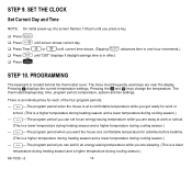
... effect. ! Press . Pressing the and keys change the temperature. Pressing displays the current temperature settings. The thermostat displays day, time, program period, temperature, system and fan settings. Return -The program period when you want the house at a comfortable temperature while you get ready for work or school. (This is a lower temperature...
... effect. ! Press . Pressing the and keys change the temperature. Pressing displays the current temperature settings. The thermostat displays day, time, program period, temperature, system and fan settings. Return -The program period when you want the house at a comfortable temperature while you get ready for work or school. (This is a lower temperature...

Owner's Manual
Page 19
...Use for improved air circulation or for more efficient central air cleaning. (In a heat-only system, fan runs continuously only if fan relay is connected to the G thermostat terminal.) Fan Auto: Normal setting for most homes. Cool: The thermostat controls your furnace filter, humidifier pad or ...replacing or cleaning your air conditioning system. SET THE FAN AND SYSTEM SWITCHES First set System switch. Heat: The thermostat controls your local contractor or visit www.honeywell.com/yourhome. Contact your heating system. Fan On: The fan runs continuously. Off: Both the heating and air ...
...Use for improved air circulation or for more efficient central air cleaning. (In a heat-only system, fan runs continuously only if fan relay is connected to the G thermostat terminal.) Fan Auto: Normal setting for most homes. Cool: The thermostat controls your furnace filter, humidifier pad or ...replacing or cleaning your air conditioning system. SET THE FAN AND SYSTEM SWITCHES First set System switch. Heat: The thermostat controls your local contractor or visit www.honeywell.com/yourhome. Contact your heating system. Fan On: The fan runs continuously. Off: Both the heating and air ...

Owner's Manual
Page 22
...SUPPLIED) CONNECT W TO Y. M12739 PROVIDE DISCONNECT MEANS AND OVERLOAD PROTECTION AS REQUIRED. 1 M10618 69-1532-2 HEATING COOLING FAN RELAY OR CONTACTOR RELAY 1 VALVE COIL COIL 1 POWER SUPPLY. PROVIDE DISCONNECT MEANS AND OVERLOAD PROTECTION AS REQUIRED. M10617... 4-WIRE SINGLE-STAGE HEAT PUMP (JUMPER INTACT) THERMOSTAT B RC O W Y R G 3 22 2 COMPRESSOR HEAT CHANGEOVER CONTACTOR 2 VALVE 1 COOL CHANGEOVER FAN VALVE RELAY 1 POWER SUPPLY. WIRING DIAGRAMS 2-WIRE HEAT-ONLY (JUMPER INTACT) THERMOSTAT B RC O W Y R G 4-WIRE HEAT/COOL (JUMPER INTACT) THERMOSTAT...
...SUPPLIED) CONNECT W TO Y. M12739 PROVIDE DISCONNECT MEANS AND OVERLOAD PROTECTION AS REQUIRED. 1 M10618 69-1532-2 HEATING COOLING FAN RELAY OR CONTACTOR RELAY 1 VALVE COIL COIL 1 POWER SUPPLY. PROVIDE DISCONNECT MEANS AND OVERLOAD PROTECTION AS REQUIRED. M10617... 4-WIRE SINGLE-STAGE HEAT PUMP (JUMPER INTACT) THERMOSTAT B RC O W Y R G 3 22 2 COMPRESSOR HEAT CHANGEOVER CONTACTOR 2 VALVE 1 COOL CHANGEOVER FAN VALVE RELAY 1 POWER SUPPLY. WIRING DIAGRAMS 2-WIRE HEAT-ONLY (JUMPER INTACT) THERMOSTAT B RC O W Y R G 4-WIRE HEAT/COOL (JUMPER INTACT) THERMOSTAT...

Owner's Manual
Page 23
... COOLING CONTACTOR COIL 1 1 POWER SUPPLY. PROVIDE DISCONNECT MEANS AND OVERLOAD PROTECTION AS REQUIRED. PROVIDE DISCONNECT MEANS AND OVERLOAD PROTECTION AS REQUIRED. FAN RELAY 1 M18738 Notice: This thermostat is a Class B digital apparatus that complies with Canadian Radio Interference Regulations, CRC c. 1374. 23 69-1532-2 M10619 HEAT DAMPER HEAT ...
... COOLING CONTACTOR COIL 1 1 POWER SUPPLY. PROVIDE DISCONNECT MEANS AND OVERLOAD PROTECTION AS REQUIRED. PROVIDE DISCONNECT MEANS AND OVERLOAD PROTECTION AS REQUIRED. FAN RELAY 1 M18738 Notice: This thermostat is a Class B digital apparatus that complies with Canadian Radio Interference Regulations, CRC c. 1374. 23 69-1532-2 M10619 HEAT DAMPER HEAT ...


