Installation Guide
Page 1
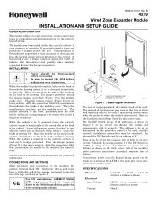
...points can exit from control's remote keypad connection points) 30mA Affix the connections label that control unit. CE For CE installations ADEMCO N6361 EMI suppression bead is used must be made via 4-terminal block TB2 or the 4-pin plug (wire color connections are ...(if room permits), or remotely. The method of programming each zone for a response time of the module's other similarly connected devices) has become inoperative. As shipped, it to the inside cover. N8924V1 5/01 Rev. B 4219 Wired Zone Expander Module INSTALLATION AND SETUP GUIDE GENERAL INFORMATION This module ...
...points can exit from control's remote keypad connection points) 30mA Affix the connections label that control unit. CE For CE installations ADEMCO N6361 EMI suppression bead is used must be made via 4-terminal block TB2 or the 4-pin plug (wire color connections are ...(if room permits), or remotely. The method of programming each zone for a response time of the module's other similarly connected devices) has become inoperative. As shipped, it to the inside cover. N8924V1 5/01 Rev. B 4219 Wired Zone Expander Module INSTALLATION AND SETUP GUIDE GENERAL INFORMATION This module ...
Installation Guide
Page 2
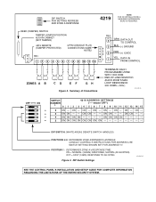
...ON ON ON ON ON ON ON ON DIP SWITCH: (WHITE AREAS DENOTE SWITCH HANDLES) POSITIONS 2-5: DETERMINE ZONE EXPANDER'S ADDRESS. ON - OFF = FAST (10MS) RESPONSE TO AN OPEN. 4219-001-V0 Figure 3. DIP Switch Settings SEE THE CONTROL PANEL'S INSTALLATION AND SETUP GUIDE FOR COMPLETE INFORMATION ... ZONES A B CD EF GH Figure 2. ON ON - - Summary of Connections TERMINATE EACH PROGRAMMED ZONE WITH 1000 OHM END-OF-LINE RESISTOR (EACH ZONE'S MAX. ON - ON - ON - 3 ON ON - - ON - SWITCH SETTING SHOWN SET FOR ADDRESS "0". DIP SWITCH FOR SETTING ADDRESS AND ZONE A RESPONSE 4219 ...
...ON ON ON ON ON ON ON ON DIP SWITCH: (WHITE AREAS DENOTE SWITCH HANDLES) POSITIONS 2-5: DETERMINE ZONE EXPANDER'S ADDRESS. ON - OFF = FAST (10MS) RESPONSE TO AN OPEN. 4219-001-V0 Figure 3. DIP Switch Settings SEE THE CONTROL PANEL'S INSTALLATION AND SETUP GUIDE FOR COMPLETE INFORMATION ... ZONES A B CD EF GH Figure 2. ON ON - - Summary of Connections TERMINATE EACH PROGRAMMED ZONE WITH 1000 OHM END-OF-LINE RESISTOR (EACH ZONE'S MAX. ON - ON - ON - 3 ON ON - - ON - SWITCH SETTING SHOWN SET FOR ADDRESS "0". DIP SWITCH FOR SETTING ADDRESS AND ZONE A RESPONSE 4219 ...


