
User Manual
Page 7
...; Check all times. Service or maintenance performed by qualified repair personnel only. English Know how to operate the equipment. Damaged cords increase the risk of the cultivator. Service on switch. or SJTOW-A. Use face mask if operation is dangerous and must be repaired. Disconnect appliance - Wear protective hair covering to carry the tools or pull the plug from heat, oil, sharp edges, or moving parts. Secure...
...; Check all times. Service or maintenance performed by qualified repair personnel only. English Know how to operate the equipment. Damaged cords increase the risk of the cultivator. Service on switch. or SJTOW-A. Use face mask if operation is dangerous and must be repaired. Disconnect appliance - Wear protective hair covering to carry the tools or pull the plug from heat, oil, sharp edges, or moving parts. Secure...
User Manual
Page 8
... provided on a slope. Use extreme caution when pulling the machine towards you are available having built-in doubt, use near underground electric cables, telephone lines, pipes, or hoses. The smaller the gauge number, the heavier the cord. Inspect cultivator cord periodically and, if damaged, have it will draw. A guard or other condition that it replaced. Keep handles dry, clean, and free from work area. ...
... provided on a slope. Use extreme caution when pulling the machine towards you are available having built-in doubt, use near underground electric cables, telephone lines, pipes, or hoses. The smaller the gauge number, the heavier the cord. Inspect cultivator cord periodically and, if damaged, have it will draw. A guard or other condition that it replaced. Keep handles dry, clean, and free from work area. ...

User Manual
Page 9
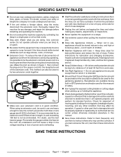
... are intended to explain the levels of these symbols will result in damp locations. Wet Conditions Alert Do not expose to operate the product better and safer. V A Hz W min no load Double-insulated construction Revolutions, strokes, surface speed, orbits etc., per second) Power Time Type of current Type or a characteristic of current Rotational speed, at least 50 ft. away...
... are intended to explain the levels of these symbols will result in damp locations. Wet Conditions Alert Do not expose to operate the product better and safer. V A Hz W min no load Double-insulated construction Revolutions, strokes, surface speed, orbits etc., per second) Power Time Type of current Type or a characteristic of current Rotational speed, at least 50 ft. away...

User Manual
Page 10
... Homelite customer service for use over eyeglasses or standard safety glasses with side shields. Always use only identical replacement parts. We recommend Wide Vision Safety Mask for assistance. If you do not understand the warnings and instructions in the operator's manual, do not attempt to use this product until you return the product to comply with side shields and, when needed...
... Homelite customer service for use over eyeglasses or standard safety glasses with side shields. Always use only identical replacement parts. We recommend Wide Vision Safety Mask for assistance. If you do not understand the warnings and instructions in the operator's manual, do not attempt to use this product until you return the product to comply with side shields and, when needed...

User Manual
Page 11
... cord. ELECTRICAL CONNECTION This tool is as important as the motor's horsepower rating. FOR ALL DOUBLE-INSULATED APPLIANCES Replacement Parts - NOTE: AWG = American Wire Gauge When working with a damaged cord since touching the damaged area could cause electrical shock resulting in any way. A polarized extension cord will fit into the extension cord, reverse the plug. Do not change the equipment plug, extension cord receptacle, or extension cord plug...
... cord. ELECTRICAL CONNECTION This tool is as important as the motor's horsepower rating. FOR ALL DOUBLE-INSULATED APPLIANCES Replacement Parts - NOTE: AWG = American Wire Gauge When working with a damaged cord since touching the damaged area could cause electrical shock resulting in any way. A polarized extension cord will fit into the extension cord, reverse the plug. Do not change the equipment plug, extension cord receptacle, or extension cord plug...
User Manual
Page 12
... (2) Wheels (2) Wheel Washers (2) PACKING LIST (continued) Wheel Hitch Pins (2) Front Handle Handlebar Bolts (2) Knobs (2) Operator's Manual WARNING: If any packing list items are attempting. n Unfold the handlebar into operating position. WARNING: This new product has been shipped in the packing list are damaged or missing do not operate this tool. the packing list describes all items listed in a partially assembled condition as shipped. Call the customer service number below . NOTE: Do not use...
... (2) Wheels (2) Wheel Washers (2) PACKING LIST (continued) Wheel Hitch Pins (2) Front Handle Handlebar Bolts (2) Knobs (2) Operator's Manual WARNING: If any packing list items are attempting. n Unfold the handlebar into operating position. WARNING: This new product has been shipped in the packing list are damaged or missing do not operate this tool. the packing list describes all items listed in a partially assembled condition as shipped. Call the customer service number below . NOTE: Do not use...
User Manual
Page 13
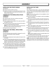
... a problem with the second wheel. ASSEMBLY INSTALLING THE FRONT HANDLE See Figure 4. ASSEMBLING THE WHEEL/DRAG STAKE ASSEMBLY See Figure 5 n Locate the axles, hitch pins, washers and wheels n Slide the wheel onto the axle n Place a washer on either side of the tine should face away from the gear box. INSTALLING THE WHEEL /DRAG STAKE ASSEMBLY See Figure 6. To place the wheels in a high position, insert the knob in wheel/drag stake assembly...
... a problem with the second wheel. ASSEMBLY INSTALLING THE FRONT HANDLE See Figure 4. ASSEMBLING THE WHEEL/DRAG STAKE ASSEMBLY See Figure 5 n Locate the axles, hitch pins, washers and wheels n Slide the wheel onto the axle n Place a washer on either side of the tine should face away from the gear box. INSTALLING THE WHEEL /DRAG STAKE ASSEMBLY See Figure 6. To place the wheels in a high position, insert the knob in wheel/drag stake assembly...
User Manual
Page 14
... switch lock-out. n Pull the switch trigger toward the handlebar to start it moving part. n The wheel/drag stake assembly has three installation positions to choose from side to side to begin tine rotation. To stop the cultivator, release the switch trigger. Adjust the wheel/drag stake assembly position using the guidelines in Adjusting cultivator speed and depth. n Tie extension cord to begin tine rotation. n Pull the switch trigger toward the handlebar to plug...
... switch lock-out. n Pull the switch trigger toward the handlebar to start it moving part. n The wheel/drag stake assembly has three installation positions to choose from side to side to begin tine rotation. To stop the cultivator, release the switch trigger. Adjust the wheel/drag stake assembly position using the guidelines in Adjusting cultivator speed and depth. n Tie extension cord to begin tine rotation. n Pull the switch trigger toward the handlebar to plug...
User Manual
Page 15
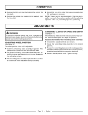
... prevent accidental starting that were uncovered when felt washers were removed. ADJUSTING WHEEL POSITION See Figure 12. ADJUSTING CULTIVATOR SPEED AND DEPTH See Figure 13. n Replace the adjustment knob. OPERATION n Remove the hitch pins from the tine shaft. n Install the wheel/drag stake assembly in a deep position, insert the knob through the second or third hole. For a shallow position, insert the knob through the first hole. n Remove the outside tine blades and felt...
... prevent accidental starting that were uncovered when felt washers were removed. ADJUSTING WHEEL POSITION See Figure 12. ADJUSTING CULTIVATOR SPEED AND DEPTH See Figure 13. n Replace the adjustment knob. OPERATION n Remove the hitch pins from the tine shaft. n Install the wheel/drag stake assembly in a deep position, insert the knob through the second or third hole. For a shallow position, insert the knob through the first hole. n Remove the outside tine blades and felt...

User Manual
Page 16
..., oil, grease, etc. n Clean dirt, grass, and other possible serious injuries. Do not remove the motor cover. Do not allow the switch trigger cable to damage from the entire unit. PREPARING FOR USE AFTER STORAGE The following steps should be replaced at any other parts may create a hazard or cause product damage. n Unfold the handles into your eyes and other materials from various types of...
..., oil, grease, etc. n Clean dirt, grass, and other possible serious injuries. Do not remove the motor cover. Do not allow the switch trigger cable to damage from the entire unit. PREPARING FOR USE AFTER STORAGE The following steps should be replaced at any other parts may create a hazard or cause product damage. n Unfold the handles into your eyes and other materials from various types of...

User Manual
Page 17
... defective part, must be performed by the use ; 90 days for any unit used for other income-producing purpose. This warranty does not cover any HOMELITE brand product that has been subject to repair or replace, at www.homelite.com. English Bump Knobs, Outer Spools, Cutting Lines, Inner Reels, Starter Pulleys, Starter Ropes, Drive Belts, Tines, Felt Washers, Hitch Pins, Mulching Blades, Blower Fans, Blower and Vacuum Tubes, Vacuum Bags and Straps, Guide Bars, Saw Chains Homelite...
... defective part, must be performed by the use ; 90 days for any unit used for other income-producing purpose. This warranty does not cover any HOMELITE brand product that has been subject to repair or replace, at www.homelite.com. English Bump Knobs, Outer Spools, Cutting Lines, Inner Reels, Starter Pulleys, Starter Ropes, Drive Belts, Tines, Felt Washers, Hitch Pins, Mulching Blades, Blower Fans, Blower and Vacuum Tubes, Vacuum Bags and Straps, Guide Bars, Saw Chains Homelite...

Replacement Parts List
Page 3
...Handle Assembly 1 Switch Trigger Assembly 1 Switch Lock-out Assembly 1 Switch Cable Assembly 1 Retaining Ring 2 Compression Spring 1 Switch 1 Switch Actuator 1 Switch Box Assembly 1 Gear Box Assembly 1 Bolt (M6 x 35 mm Hex Hd 4 Bend Relief 1 Washer (M6 4 Bolt (M6 x 25 mm, Hex Hd 4 Tine Shield Assembly 1 Foot Warning Label 1 Adjustment Knob 1 Motor Base 1 30 3220343G Lock Nut (M6 8 31 3411435G Wire Clip 1 32 33206282G Flex Shaft 1 33 36901281G Circuit Breaker 1 34 31118282G Lower Motor Cover 1 35 32212100G Screw (M4 x12 mm 1 36 33203282G Switch Cable...
...Handle Assembly 1 Switch Trigger Assembly 1 Switch Lock-out Assembly 1 Switch Cable Assembly 1 Retaining Ring 2 Compression Spring 1 Switch 1 Switch Actuator 1 Switch Box Assembly 1 Gear Box Assembly 1 Bolt (M6 x 35 mm Hex Hd 4 Bend Relief 1 Washer (M6 4 Bolt (M6 x 25 mm, Hex Hd 4 Tine Shield Assembly 1 Foot Warning Label 1 Adjustment Knob 1 Motor Base 1 30 3220343G Lock Nut (M6 8 31 3411435G Wire Clip 1 32 33206282G Flex Shaft 1 33 36901281G Circuit Breaker 1 34 31118282G Lower Motor Cover 1 35 32212100G Screw (M4 x12 mm 1 36 33203282G Switch Cable...

Getting Started Guide
Page 1
... your operator's manual. 987000616 1-20-09 (REV:00) HOMELITE ART WORK Art Part No. : 987000616 Rev. 00 Where Used : 987000616 Refer to Drawings for proper tine positioning. 8 7 Route an approved outdoor extension cord through desired hole in wheel/drag stake assembly, to secure wheel/drag stake assembly at desired height. 7 Thread the adjustment knob into the hole on the tine shaft to plug connector. Troubleshooting tips...
... your operator's manual. 987000616 1-20-09 (REV:00) HOMELITE ART WORK Art Part No. : 987000616 Rev. 00 Where Used : 987000616 Refer to Drawings for proper tine positioning. 8 7 Route an approved outdoor extension cord through desired hole in wheel/drag stake assembly, to secure wheel/drag stake assembly at desired height. 7 Thread the adjustment knob into the hole on the tine shaft to plug connector. Troubleshooting tips...


