

User Manual
Page 1
UT13120 Your lawn mower has been engineered and manufactured to our high standard for your purchase. SAVE THIS MANUAL FOR FUTURE REFERENCE OPERATOR'S MANUAL ELECTRIC LAWN MOWER 18 in . - WARNING: To reduce the risk of operation, and operator safety. Thank you years of rugged, trouble-free performance. UT13118 20 in . - Properly cared for, it will give you for dependability, ease of injury, the user must read and understand the operator's manual before using this product.
UT13120 Your lawn mower has been engineered and manufactured to our high standard for your purchase. SAVE THIS MANUAL FOR FUTURE REFERENCE OPERATOR'S MANUAL ELECTRIC LAWN MOWER 18 in . - WARNING: To reduce the risk of operation, and operator safety. Thank you years of rugged, trouble-free performance. UT13118 20 in . - Properly cared for, it will give you for dependability, ease of injury, the user must read and understand the operator's manual before using this product.

User Manual
Page 2
... Introduction ...2 General Safety Rules...3-4 Specific Safety Rules ...4 Symbols ...5-6 Electrical...7 Features...8-9 Assembly...9-11 Operation...12-13 Maintenance...14-16 Troubleshooting...17 Exploded View/Parts List ...18-19 Warranty ...20 Parts Ordering / Service ...Back Page INTRODUCTION This product has many features for making it easy to maintain and operate. Safety, performance, and dependability have...
... Introduction ...2 General Safety Rules...3-4 Specific Safety Rules ...4 Symbols ...5-6 Electrical...7 Features...8-9 Assembly...9-11 Operation...12-13 Maintenance...14-16 Troubleshooting...17 Exploded View/Parts List ...18-19 Warranty ...20 Parts Ordering / Service ...Back Page INTRODUCTION This product has many features for making it easy to maintain and operate. Safety, performance, and dependability have...
User Manual
Page 3
... the lawn mower, removing the grass catcher, or unclogging the discharge guard. When not in serious injury or death. Do not use the lawn mower for any way. Do not abuse the cord. If the plug does not fit fully into the wall outlet, reverse the plug. If the plug does not fit fully into the extension cord, reverse the plug. Do not change the equipment plug...
... the lawn mower, removing the grass catcher, or unclogging the discharge guard. When not in serious injury or death. Do not use the lawn mower for any way. Do not abuse the cord. If the plug does not fit fully into the wall outlet, reverse the plug. If the plug does not fit fully into the extension cord, reverse the plug. Do not change the equipment plug...
User Manual
Page 4
... not operate the mower without the entire grass catcher, discharge guard, rear guard, or other objects which may use them these steps: • Stop the lawn mower and release the switch control lever. • Disconnect the power cord. • Thoroughly inspect the mower for the lawn mower. Exercise extreme caution when changing direction on slopes. Plan your view. Do not pull the mower backward unless absolutely necessary. The cutting blade continues...
... not operate the mower without the entire grass catcher, discharge guard, rear guard, or other objects which may use them these steps: • Stop the lawn mower and release the switch control lever. • Disconnect the power cord. • Thoroughly inspect the mower for the lawn mower. Exercise extreme caution when changing direction on slopes. Plan your view. Do not pull the mower backward unless absolutely necessary. The cutting blade continues...
User Manual
Page 6
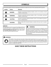
Call Homelite customer service for repair. Always use eye protection which is marked to comply with side shields. For service we suggest you do not understand the warnings and instructions in the operator's manual, do not attempt to use only identical replacement parts. SYMBOL SIGNAL MEANING DANGER: Indicates an imminently hazardous situation, which can result in severe eye damage. WARNING: The operation of...
Call Homelite customer service for repair. Always use eye protection which is marked to comply with side shields. For service we suggest you do not understand the warnings and instructions in the operator's manual, do not attempt to use only identical replacement parts. SYMBOL SIGNAL MEANING DANGER: Indicates an imminently hazardous situation, which can result in severe eye damage. WARNING: The operation of...
User Manual
Page 7
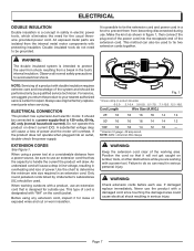
...-check the power supply. Failure to do not need for loose or exposed wires and cut or worn insulation. Make the knot as shown in an extension cord. ELECTRICAL DOUBLE INSULATION Double insulation is a concept in safety in electric power tools, which eliminates the need to be sure to use an...
...-check the power supply. Failure to do not need for loose or exposed wires and cut or worn insulation. Make the knot as shown in an extension cord. ELECTRICAL DOUBLE INSULATION Double insulation is a concept in safety in electric power tools, which eliminates the need to be sure to use an...

User Manual
Page 8
... 3-3/4 in . CORD RETAINER GRASS CATCHER (MODEL UT13120 ONLY) HEIGHT ADJUSTMENT LEVER MOTOR/BLADE CONTROL ASSEMBLY SIDE DISCHARGE DEFLECTOR MULCHING PLUG (MODEL UT13120 ONLY) Page 8 Fig. 2 to 3-3/4 in . UT13120 Input 120 V, 60 Hz, AC only, 12 Amps No-load Speed 3,600 r/min. (RPM) Cutting Path 20 in . front, 8 in . Height Adjustments 1-3/4 in . Weight 42 lb. Wheel Size 7 in . Wheel Size 7 in . rear Weight 53 lb. Height Adjustments 1-1/2 in . FEATURES PRODUCT SPECIFICATIONS UT13118 Input 120 V, 60...
... 3-3/4 in . CORD RETAINER GRASS CATCHER (MODEL UT13120 ONLY) HEIGHT ADJUSTMENT LEVER MOTOR/BLADE CONTROL ASSEMBLY SIDE DISCHARGE DEFLECTOR MULCHING PLUG (MODEL UT13120 ONLY) Page 8 Fig. 2 to 3-3/4 in . UT13120 Input 120 V, 60 Hz, AC only, 12 Amps No-load Speed 3,600 r/min. (RPM) Cutting Path 20 in . front, 8 in . Height Adjustments 1-3/4 in . Weight 42 lb. Wheel Size 7 in . Wheel Size 7 in . rear Weight 53 lb. Height Adjustments 1-1/2 in . FEATURES PRODUCT SPECIFICATIONS UT13118 Input 120 V, 60...
User Manual
Page 9
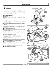
.... WARNING: Do not attempt to power supply until the parts are noticeably larger than those produced when using the side discharge deflector are replaced. WARNING: Do not connect to modify this product. Make sure that cuts and recuts the grass for assistance. HEIGHT ADJUSTMENT LEVER The height adjustment lever provides cutting height adjustments. MULCHING PLUG (MODEL UT13120 ONLY) Your mower is complete. Before use with a mulching plug that all operating features and safety rules. FE...
.... WARNING: Do not attempt to power supply until the parts are noticeably larger than those produced when using the side discharge deflector are replaced. WARNING: Do not connect to modify this product. Make sure that cuts and recuts the grass for assistance. HEIGHT ADJUSTMENT LEVER The height adjustment lever provides cutting height adjustments. MULCHING PLUG (MODEL UT13120 ONLY) Your mower is complete. Before use with a mulching plug that all operating features and safety rules. FE...
User Manual
Page 10
NOTE: When using the mulching plug, do not install either the side discharge deflector or the grass catcher. Lift the rear discharge door. Grasp the mulching plug by its handle and tilt at an approximate 15 degree angle. Insert the plug into operating position. INSTALLING THE MULCHING PLUG (MODEL UT13120 ONLY) See Figure 5. ASSEMBLY WARNING: Never operate the mower without the proper safety devices in serious personal injury. Never operate the mower with the...
NOTE: When using the mulching plug, do not install either the side discharge deflector or the grass catcher. Lift the rear discharge door. Grasp the mulching plug by its handle and tilt at an approximate 15 degree angle. Insert the plug into operating position. INSTALLING THE MULCHING PLUG (MODEL UT13120 ONLY) See Figure 5. ASSEMBLY WARNING: Never operate the mower without the proper safety devices in serious personal injury. Never operate the mower with the...
User Manual
Page 11
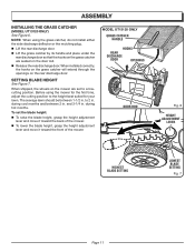
... height adjustment lever and move it toward the front of the mower. When shipped, the wheels on the mower are seated on the door rod. Release the rear discharge door. To set to a lowcutting position. ASSEMBLY INSTALLING THE GRASS CATCHER (MODEL UT13120 ONLY) See Figure 6. and 3-1/4 in . NOTE: When using the mower for your lawn. The average lawn should be between 2 in . MODEL UT13120 ONLY GRASS CATCHER HANDLE HOOKS REAR DISCHARGE DOOR OPENINGS DOOR ROD Fig. 6 HEIGHT ADJUSTMENT LEVER HIGHEST BLADE SETTING LOWEST BLADE SETTING...
... height adjustment lever and move it toward the front of the mower. When shipped, the wheels on the mower are seated on the door rod. Release the rear discharge door. To set to a lowcutting position. ASSEMBLY INSTALLING THE GRASS CATCHER (MODEL UT13120 ONLY) See Figure 6. and 3-1/4 in . NOTE: When using the mower for your lawn. The average lawn should be between 2 in . MODEL UT13120 ONLY GRASS CATCHER HANDLE HOOKS REAR DISCHARGE DOOR OPENINGS DOOR ROD Fig. 6 HEIGHT ADJUSTMENT LEVER HIGHEST BLADE SETTING LOWEST BLADE SETTING...
User Manual
Page 12
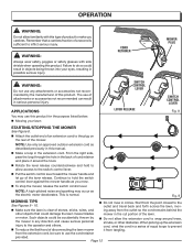
... injury. NOTE: A high-pitched noise and sparking may use of attachments or accessories not recommended can result in circles. This is sufficient to hold to allow the extension cord to the switch control lever. � Pull the switch control lever toward the mower handle and let go of the lever release. Such objects could damage the lawn mower blades mower in the extension cord. Fig. 9 MOWING TIPS See Figures...
... injury. NOTE: A high-pitched noise and sparking may use of attachments or accessories not recommended can result in circles. This is sufficient to hold to allow the extension cord to the switch control lever. � Pull the switch control lever toward the mower handle and let go of the lever release. Such objects could damage the lawn mower blades mower in the extension cord. Fig. 9 MOWING TIPS See Figures...
User Manual
Page 13
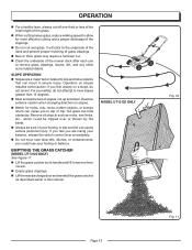
...; Lift the grass catcher by its handle and lift to remove from mower. Empty grass clippings. Lift the rear discharge door and reinstall the grass catcher as rocks, tree limbs, etc., which can hide obstacles. OPERATION For a healthy lawn, always cut off one-third or less of the total length of the grass. � When cutting heavy grass, reduce walking speed to allow for...
...; Lift the grass catcher by its handle and lift to remove from mower. Empty grass clippings. Lift the rear discharge door and reinstall the grass catcher as rocks, tree limbs, etc., which can hide obstacles. OPERATION For a healthy lawn, always cut off one-third or less of the total length of the grass. � When cutting heavy grass, reduce walking speed to allow for...
User Manual
Page 14
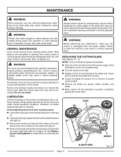
.... MAINTENANCE WARNING: When servicing, use identical replacement blades. Stop the motor and disconnect the power supply. See Replacing the Cutting Blade for proper tightness to remove dirt, dust, oil, grease, etc. Do not use . Use of the unit under normal operating conditions. Use clean cloths to ensure safe operation of wood between the blade and mower deck to a complete stop. Turn the mower on removing the blade. Periodically check all nuts and bolts for instructions on...
.... MAINTENANCE WARNING: When servicing, use identical replacement blades. Stop the motor and disconnect the power supply. See Replacing the Cutting Blade for proper tightness to remove dirt, dust, oil, grease, etc. Do not use . Use of the unit under normal operating conditions. Use clean cloths to ensure safe operation of wood between the blade and mower deck to a complete stop. Turn the mower on removing the blade. Periodically check all nuts and bolts for instructions on...
User Manual
Page 15
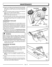
... Cutting Blade section, remove the mower blade. Failure to replace a bent or damaged blade could cause an accident resulting in which they were removed. Torque the blade nut down toward the mower deck and not down using a torque wrench (not provided) to the mower. SHARPENING THE BLADE See Figure 14. NOTE: If a vise is balanced. A dull blade does not cut grass evenly and overloads the motor. However, if your lawn...
... Cutting Blade section, remove the mower blade. Failure to replace a bent or damaged blade could cause an accident resulting in which they were removed. Torque the blade nut down toward the mower deck and not down using a torque wrench (not provided) to the mower. SHARPENING THE BLADE See Figure 14. NOTE: If a vise is balanced. A dull blade does not cut grass evenly and overloads the motor. However, if your lawn...
User Manual
Page 16
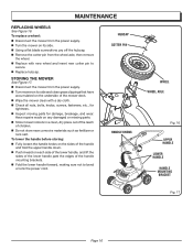
... grass clippings that have accumulated on its side. Using a flat blade screwdriver, pry off the hubcap. Remove the cotter pin from the power supply. � Turn the mower on the underside of the mower deck. Wipe the mower clean with new wheel and insert new cotter pin to bend or kink the power cord. To replace a wheel: Disconnect the mower from the wheel...
... grass clippings that have accumulated on its side. Using a flat blade screwdriver, pry off the hubcap. Remove the cotter pin from the power supply. � Turn the mower on the underside of the mower deck. Wipe the mower clean with new wheel and insert new cotter pin to bend or kink the power cord. To replace a wheel: Disconnect the mower from the wheel...
User Manual
Page 17
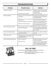
... seated properly. Reset house circuit breaker. Wet grass clippings sticking to push. mowing. Blade is rough or uneven or cutting height not set properly. Balance the blade by an authorized service center. Extension cord not connected to cut evenly. All wheels must be placed in heavy grass, or cutting height too low. Adjust the height of mower housing and blade dragging in the same cutting height for damage. Have motor control switch replaced by grinding each cutting edge equally. Lawn...
... seated properly. Reset house circuit breaker. Wet grass clippings sticking to push. mowing. Blade is rough or uneven or cutting height not set properly. Balance the blade by an authorized service center. Extension cord not connected to cut evenly. All wheels must be placed in heavy grass, or cutting height too low. Adjust the height of mower housing and blade dragging in the same cutting height for damage. Have motor control switch replaced by grinding each cutting edge equally. Lawn...
User Manual
Page 18
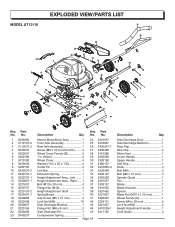
... Key Part Qty. Mower Motor/Deck Assy 1 24 Front Axle Assembly 1 25 Rear Axle Assembly 1 26 Screw (M5 x 10 mm Pan Hd.)......... 4 27 Wheel Cover Ferrule (B 3 28 7 in. No. Side Discharge Door 1 Side Discharge Deflector 1 Rear Flap 1 Wire Clip 2 Motor Vent 1 Lower Handle 1 Upper Handle 1 Soft Grip 1 Knob 4 Bolt (M8 2 Bolt (M6 x 12 mm 3 Spindle Guard 1 Fan 1 Blade 1 Blade Insulator 1 Spacer 1 Blade Nut (M10 x 1.25 mm 1 Wheel Ferrule (A 1 Screw (M4 x 20 mm 2 Lock Nut (M4 2 Height Adjustment Handle 1 Cord Guide...
... Key Part Qty. Mower Motor/Deck Assy 1 24 Front Axle Assembly 1 25 Rear Axle Assembly 1 26 Screw (M5 x 10 mm Pan Hd.)......... 4 27 Wheel Cover Ferrule (B 3 28 7 in. No. Side Discharge Door 1 Side Discharge Deflector 1 Rear Flap 1 Wire Clip 2 Motor Vent 1 Lower Handle 1 Upper Handle 1 Soft Grip 1 Knob 4 Bolt (M8 2 Bolt (M6 x 12 mm 3 Spindle Guard 1 Fan 1 Blade 1 Blade Insulator 1 Spacer 1 Blade Nut (M10 x 1.25 mm 1 Wheel Ferrule (A 1 Screw (M4 x 20 mm 2 Lock Nut (M4 2 Height Adjustment Handle 1 Cord Guide...
User Manual
Page 19
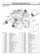
... 42 48 47 Key Part No. Wire Clip 2 Side Discharge Bracket 1 Flange Nut (M6 x 8 mm 2 Side Discharge Pin 1 Side Compression Spring 1 Side Discharge Door 1 Side Discharge Deflector 1 Motor Vent 1 Flange Nut (M6 x 12 mm 3 Spindle Guard 1 Fan 1 Blade Insulator 1 Spacer 1 Blade 1 Blade Nut (M10 x 1.25 mm 1 Upper Handle 1 Lower Handle 1 Soft Grip 1 Bolt (M8 2 Screw (M4 x 20 mm pan hd 2 Grass Catcher Frame 1 Knob 4 Lock Nut (M4 2 Grass Catcher 1 Cord Guide 3 "O" ring 2 No. 1 3130191...
... 42 48 47 Key Part No. Wire Clip 2 Side Discharge Bracket 1 Flange Nut (M6 x 8 mm 2 Side Discharge Pin 1 Side Compression Spring 1 Side Discharge Door 1 Side Discharge Deflector 1 Motor Vent 1 Flange Nut (M6 x 12 mm 3 Spindle Guard 1 Fan 1 Blade Insulator 1 Spacer 1 Blade 1 Blade Nut (M10 x 1.25 mm 1 Upper Handle 1 Lower Handle 1 Soft Grip 1 Bolt (M8 2 Screw (M4 x 20 mm pan hd 2 Grass Catcher Frame 1 Knob 4 Lock Nut (M4 2 Grass Catcher 1 Cord Guide 3 "O" ring 2 No. 1 3130191...

User Manual
Page 20
... operator's manual. Damage or liability caused by shipping, improper handling, improper installation, incorrect voltage or improper wiring, improper maintenance, improper modification, or the use of accessories and/or attachments not specifically recommended. Repairs necessary because of operator abuse or negligence, or the failure to install, operate, maintain, and store the product according to the instructions in material and workmanship and agrees to repair or replace...
... operator's manual. Damage or liability caused by shipping, improper handling, improper installation, incorrect voltage or improper wiring, improper maintenance, improper modification, or the use of accessories and/or attachments not specifically recommended. Repairs necessary because of operator abuse or negligence, or the failure to install, operate, maintain, and store the product according to the instructions in material and workmanship and agrees to repair or replace...

User Manual
Page 22
UT13120 SERVICE For parts or service, contact your nearest Homelite authorized service dealer. OPERATOR'S MANUAL ELECTRIC LAWN MOWER 18 in . - Be sure to the housing. UT13118 20 in . - REPAIR PARTS The model number of the authorized service dealer nearest you call 1-866-457-5888 or visit us online at www.homelite.com. For the location of this tool is found on a plate or label attached to provide all relevant information when you...
UT13120 SERVICE For parts or service, contact your nearest Homelite authorized service dealer. OPERATOR'S MANUAL ELECTRIC LAWN MOWER 18 in . - Be sure to the housing. UT13118 20 in . - REPAIR PARTS The model number of the authorized service dealer nearest you call 1-866-457-5888 or visit us online at www.homelite.com. For the location of this tool is found on a plate or label attached to provide all relevant information when you...


