
Specifications
Page 4
... possible that this publication may contain reference to, or information about this product is subject to the information herein; these patents. ©Copyright Hitachi Globlal Storage Technologies Note to U.S. Changes are periodically made to restrictions set forth in your country. This publication could include technical inaccuracies or typographical errors. Technical information about...
... possible that this publication may contain reference to, or information about this product is subject to the information herein; these patents. ©Copyright Hitachi Globlal Storage Technologies Note to U.S. Changes are periodically made to restrictions set forth in your country. This publication could include technical inaccuracies or typographical errors. Technical information about...

Specifications
Page 5
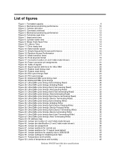
Table of contents List of registers 38 6.2.6 Cabling 38 6.3 Jumper settings 39 6.3.1 Jumper pin location 39 6.3.2 Jumper pin identification 39 6.3.3 Jumper pin assignment 40 6.3.4 Jumper positions 41 6.4 Environment 45 6.4.1 Temperature and humidity 45 6.4.2 Corrosion test 46 6.5 DC power requirements 47 Deskstar 180GXP hard disk drive specifications v Functional specification 5 3.0 Fixed disk subsystem description 7 3.1 Control Electronics 7 3.2 Head...
Table of contents List of registers 38 6.2.6 Cabling 38 6.3 Jumper settings 39 6.3.1 Jumper pin location 39 6.3.2 Jumper pin identification 39 6.3.3 Jumper pin assignment 40 6.3.4 Jumper positions 41 6.4 Environment 45 6.4.1 Temperature and humidity 45 6.4.2 Corrosion test 46 6.5 DC power requirements 47 Deskstar 180GXP hard disk drive specifications v Functional specification 5 3.0 Fixed disk subsystem description 7 3.1 Control Electronics 7 3.2 Head...

Specifications
Page 7
... 91 9.15.1 Enable/Disable Address Offset Mode 91 9.15.2 Identify Device Data 92 9.15.3 Exceptions in Address Offset Mode 92 9.16 48-bit Address Feature Set 93 10.0 Command Protocol 95 10.1 PIO Data In commands 96 10.2 PIO Data Out commands 98 10.3 Non-data commands 100 10.4 DMA commands... 11.2.1 DEVICE CONFIGURATION RESTORE (subcommand C0h 110 11.2.2 DEVICE CONFIGURATION FREEZE LOCK (subcommand C1h 111 11.2.3 DEVICE CONFIGURATION IDENTIFY (subcommand C2h 111 11.2.4 DEVICE CONFIGURATION SET (subcommand C3h 111 Deskstar 180GXP hard disk drive specifications vii
... 91 9.15.1 Enable/Disable Address Offset Mode 91 9.15.2 Identify Device Data 92 9.15.3 Exceptions in Address Offset Mode 92 9.16 48-bit Address Feature Set 93 10.0 Command Protocol 95 10.1 PIO Data In commands 96 10.2 PIO Data Out commands 98 10.3 Non-data commands 100 10.4 DMA commands... 11.2.1 DEVICE CONFIGURATION RESTORE (subcommand C0h 110 11.2.2 DEVICE CONFIGURATION FREEZE LOCK (subcommand C1h 111 11.2.3 DEVICE CONFIGURATION IDENTIFY (subcommand C2h 111 11.2.4 DEVICE CONFIGURATION SET (subcommand C3h 111 Deskstar 180GXP hard disk drive specifications vii
Specifications
Page 11
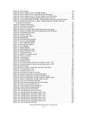
...36. Ultra DMA cycle timing chart (Device Terminating Write 36 Figure 40. and 3-disk model shown 39 Figure 45. Jumper settings for Ultra DMA 22 Figure 21. Head switch time 13 Figure 8. Connector location (2- Ultra DMA cycle timing chart (Device ... Terminating Read 33 Figure 35. Latency Time 14 Figure 11. Jumper pin location (2- List of temperature and humidity 46 Deskstar 180GXP hard disk drive specifications xi Mechanical positioning performance 10 Figure 3. Cylinder allocation 11 Figure 4. Command overhead 12 Figure 5. PList physical format ...
...36. Ultra DMA cycle timing chart (Device Terminating Write 36 Figure 40. and 3-disk model shown 39 Figure 45. Jumper settings for Ultra DMA 22 Figure 21. Head switch time 13 Figure 8. Connector location (2- Ultra DMA cycle timing chart (Device ... Terminating Read 33 Figure 35. Latency Time 14 Figure 11. Jumper pin location (2- List of temperature and humidity 46 Deskstar 180GXP hard disk drive specifications xi Mechanical positioning performance 10 Figure 3. Cylinder allocation 11 Figure 4. Command overhead 12 Figure 5. PList physical format ...
Specifications
Page 12
...56 Figure 66. Diagnostic Codes 72 Figure 78. Usual Operation 82 Figure 82. Seek overlap 88 Figure 86. Command set (1 of 60 GB, 40GB, and 30 GB models 48 Figure 57. Device Configuration Overlay Data structure 112 Figure 94. Identify Device Information (part 1 of 6 122... Device Information (part 4 of 2 106 Figure 89. Idle Command (E3h/97h 127 Deskstar 180GXP hard disk drive specifications xii Command set (2 of 6 124 Figure 105. Identify Device Information (part 6 of 180 GB models 47 Figure 55. Power supply current of 6 126 Figure 107. Device/Head Register...
...56 Figure 66. Diagnostic Codes 72 Figure 78. Usual Operation 82 Figure 82. Seek overlap 88 Figure 86. Command set (1 of 60 GB, 40GB, and 30 GB models 48 Figure 57. Device Configuration Overlay Data structure 112 Figure 94. Identify Device Information (part 1 of 6 122... Device Information (part 4 of 2 106 Figure 89. Idle Command (E3h/97h 127 Deskstar 180GXP hard disk drive specifications xii Command set (2 of 6 124 Figure 105. Identify Device Information (part 6 of 180 GB models 47 Figure 55. Power supply current of 6 126 Figure 107. Device/Head Register...

Specifications
Page 13
...Command (F3h 165 Figure 138. Security Unlock Information 172 Figure 145. Service Command (A2h 174 Figure 147. Set Max Set Password data contents 181 Figure 151. Set Max Freeze Lock (F9h 184 Figure 154. Sleep Command (E6h/99h 188 Figure 157. S.M.A.R.T. Device Attributes ... structure 145 Figure 124. Security Unlock Command (F2h 171 Figure 144. Set Multiple Command (C6h 187 Figure 156. Log sector addresses 192 Figure 159. SMART Log Directory 199 Deskstar 180GXP hard disk drive specifications xiii Initialize Device Parameters Command (91h 129 Figure 110. Read Buffer...
...Command (F3h 165 Figure 138. Security Unlock Information 172 Figure 145. Service Command (A2h 174 Figure 147. Set Max Set Password data contents 181 Figure 151. Set Max Freeze Lock (F9h 184 Figure 154. Sleep Command (E6h/99h 188 Figure 157. S.M.A.R.T. Device Attributes ... structure 145 Figure 124. Security Unlock Command (F2h 171 Figure 144. Set Multiple Command (C6h 187 Figure 156. Log sector addresses 192 Figure 159. SMART Log Directory 199 Deskstar 180GXP hard disk drive specifications xiii Initialize Device Parameters Command (91h 129 Figure 110. Read Buffer...

Specifications
Page 23
The default setting can be obtained by issuing an IDENTIFY DEVICE command Deskstar 180GXP hard disk drive specifications 9 Description IC35L030AVV207 IC35L060AVV207 IC35L060AVV207 Optimized 40 GB Physical Layout Label capacity (GB) 30 40 40 Bytes per Sector 512 512 512 Sectors per Track 536-1092 536-1092 630-1008 Number of Heads 1 2 2 Number of ... of Cylinders2 16,383 16,383 16,383 Number of Sectors 60,036,480 80,418,240 80,418,240 Total Logical Data Bytes 30,738,677,760 41,174,138,880 41,174,138,880 IC35L060AVV207 60 512 536-1092 2 1 1072-2184 857-4481 16 63 ...
The default setting can be obtained by issuing an IDENTIFY DEVICE command Deskstar 180GXP hard disk drive specifications 9 Description IC35L030AVV207 IC35L060AVV207 IC35L060AVV207 Optimized 40 GB Physical Layout Label capacity (GB) 30 40 40 Bytes per Sector 512 512 512 Sectors per Track 536-1092 536-1092 630-1008 Number of Heads 1 2 2 Number of ... of Cylinders2 16,383 16,383 16,383 Number of Sectors 60,036,480 80,418,240 80,418,240 Total Logical Data Bytes 30,738,677,760 41,174,138,880 41,174,138,880 IC35L060AVV207 60 512 536-1092 2 1 1072-2184 857-4481 16 63 ...

Specifications
Page 37
... device 1 has passed its own status immediately after RESET- If device 1 is busy). The interrupt is set by Device 1 within 1 ms to indicate to indicate that it is in the drive. DASP- to indicate that it is no later than after negation of the IRQ bit. PDIAG- no...present. Following the receipt of the status register or a write to 5 volts in the Device Control Reg. CSEL (Cable Select) (Optional) Deskstar 180GXP hard disk drive specifications 23 CS1RESETDIOW- When active one of the Control Block Registers (Alternate Status {Device Control when written} and...
... device 1 has passed its own status immediately after RESET- If device 1 is busy). The interrupt is set by Device 1 within 1 ms to indicate to indicate that it is in the drive. DASP- to indicate that it is no later than after negation of the IRQ bit. PDIAG- no...present. Following the receipt of the status register or a write to 5 volts in the Device Control Reg. CSEL (Cable Select) (Optional) Deskstar 180GXP hard disk drive specifications 23 CS1RESETDIOW- When active one of the Control Block Registers (Alternate Status {Device Control when written} and...

Specifications
Page 41
... 3.8 µs is inserted from the end of negation of the DRQ bit until setting of the ATA/ATAPI-6 description. recovery time t3 DIOW- data setup t6 DIOR- data hold t5 DIOR- MAX (ns) 35 1250 Figure 24. Deskstar 180GXP hard disk drive specifications 27 setup t2 DIOR-/DIOW- pulse width t2i DIOR-/DIOW- CS... t2i t3 t4 t5 t6 tA tB (*) Up to ATA-2 (mode-0,1,2) PARAMETER DESCRIPTION t0 Cycle time t1 Address valid to address valid hold tA IORDY set up time tB IORDY pulse width MIN (ns) 120 25 70 25 20 10 20 5 10 - -
... 3.8 µs is inserted from the end of negation of the DRQ bit until setting of the ATA/ATAPI-6 description. recovery time t3 DIOW- data setup t6 DIOR- data hold t5 DIOR- MAX (ns) 35 1250 Figure 24. Deskstar 180GXP hard disk drive specifications 27 setup t2 DIOR-/DIOW- pulse width t2i DIOR-/DIOW- CS... t2i t3 t4 t5 t6 tA tB (*) Up to ATA-2 (mode-0,1,2) PARAMETER DESCRIPTION t0 Cycle time t1 Address valid to address valid hold tA IORDY set up time tB IORDY pulse width MIN (ns) 120 25 70 25 20 10 20 5 10 - -

Specifications
Page 42
6.2.2.2 Read DRQ interval time For read sectors and read multiple operations the interval from the end of negation of the DRQ bit until setting of the next DRQ bit is as follows: y In the event that a host reads the status register only before the sector or block transfer DRQ interval, the DRQ interval 4.2 µs y In the event that a host reads the status register after or both before and after the sector or block transfer, the DRQ interval is 11.5 µs Deskstar 180GXP hard disk drive specifications 28
6.2.2.2 Read DRQ interval time For read sectors and read multiple operations the interval from the end of negation of the DRQ bit until setting of the next DRQ bit is as follows: y In the event that a host reads the status register only before the sector or block transfer DRQ interval, the DRQ interval 4.2 µs y In the event that a host reads the status register after or both before and after the sector or block transfer, the DRQ interval is 11.5 µs Deskstar 180GXP hard disk drive specifications 28

Specifications
Page 52
... register contents before interrupt (the value is invalid). 6.2.6 Cabling The maximum cable length from writing to select one of registers called the Task File. Deskstar 180GXP hard disk drive specifications 38 is shown as a shorter cable, bus termination, or a shielded cable. is recommended to address Command Block registers. DA2 0 1 0 0 1 0 0 1 0 0 1 0 0 1 ...Sector number Reg. 0 Cylinder low Reg. Cylinder high Reg. 0 Drive/Head Reg. 6.2.5 Addressing of registers The host addresses the drive through a set of these registers, while a DIOR- and CS1-) and three ...
... register contents before interrupt (the value is invalid). 6.2.6 Cabling The maximum cable length from writing to select one of registers called the Task File. Deskstar 180GXP hard disk drive specifications 38 is shown as a shorter cable, bus termination, or a shielded cable. is recommended to address Command Block registers. DA2 0 1 0 0 1 0 0 1 0 0 1 0 0 1 ...Sector number Reg. 0 Cylinder low Reg. Cylinder high Reg. 0 Drive/Head Reg. 6.2.5 Addressing of registers The host addresses the drive through a set of these registers, while a DIOR- and CS1-) and three ...

Specifications
Page 54
... that does not comply with the ATA specification. Jumper pin assignment Deskstar 180GXP hard disk drive specifications 40 6.3.3 Jumper pin assignment There are four jumper settings as shown in the following sections: y 16 logical head default (normal use) y 15 logical head default y 2 GB/32 GB clip y Power up in standby Within each of these four jumper...
... that does not comply with the ATA specification. Jumper pin assignment Deskstar 180GXP hard disk drive specifications 40 6.3.3 Jumper pin assignment There are four jumper settings as shown in the following sections: y 16 logical head default (normal use) y 15 logical head default y 2 GB/32 GB clip y Power up in standby Within each of these four jumper...

Specifications
Page 56
... head default The figure below shows the jumper positions used to select Device 0, Device 1, Cable Selection, or Device 1 (Slave) Present setting 15 logical heads instead of Device or Cable Selection mode. To enable the CSEL mode (Cable Selection mode) the jumper block must be ...installed at a high level, the drive address is open or at E-F. I GECA HFDB DEVICE 0 (Master) I GECA HF DB DEVICE 1 (Slave) IGECA HFDB CABLE SEL I GECA HFDB DEVICE 1 (Slave) Present Figure 48. Deskstar 180GXP hard disk drive specifications 42 y When CSEL is 1 (Device 1). 2. Jumper...
... head default The figure below shows the jumper positions used to select Device 0, Device 1, Cable Selection, or Device 1 (Slave) Present setting 15 logical heads instead of Device or Cable Selection mode. To enable the CSEL mode (Cable Selection mode) the jumper block must be ...installed at a high level, the drive address is open or at E-F. I GECA HFDB DEVICE 0 (Master) I GECA HF DB DEVICE 1 (Slave) IGECA HFDB CABLE SEL I GECA HFDB DEVICE 1 (Slave) Present Figure 48. Deskstar 180GXP hard disk drive specifications 42 y When CSEL is 1 (Device 1). 2. Jumper...
Specifications
Page 57
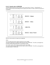
...default setting (dependent on the particular model). Deskstar 180GXP hard disk drive specifications 43 The CHS is unchanged from the factory default of compatibility. Jumper positions for the purpose of 16383/16/63. For all other models (factory default capacities greater than 32GB): The jumper setting ...1, Cable Selection, or Device 1 (Slave) Present while setting the drive capacity down either to 2 GB or 32 GB for capacity clip to 2GB/32GB Notes: For the 30-GB model (factory default capacities less than 32GB): The jumper setting acts as a 2GB clip which clips the LBA to ...
...default setting (dependent on the particular model). Deskstar 180GXP hard disk drive specifications 43 The CHS is unchanged from the factory default of compatibility. Jumper positions for the purpose of 16383/16/63. For all other models (factory default capacities greater than 32GB): The jumper setting ...1, Cable Selection, or Device 1 (Slave) Present while setting the drive capacity down either to 2 GB or 32 GB for capacity clip to 2GB/32GB Notes: For the 30-GB model (factory default capacities less than 32GB): The jumper setting acts as a 2GB clip which clips the LBA to ...

Specifications
Page 58
Deskstar 180GXP hard disk drive specifications 44 These jumper settings are used for Disabling Auto Spin Notes: 1. Refer to spin up is SET FEATURES (subcommand 07h). To enable the CSEL mode (Cable Selection mode) the jumper block must be installed at a low level, the drive address is 1 (Device 1). y When CSEL is open or at a high level, the...
Deskstar 180GXP hard disk drive specifications 44 These jumper settings are used for Disabling Auto Spin Notes: 1. Refer to spin up is SET FEATURES (subcommand 07h). To enable the CSEL mode (Cable Selection mode) the jumper block must be installed at a low level, the drive address is 1 (Device 1). y When CSEL is open or at a high level, the...

Specifications
Page 64
... performance throughput or error rate when the interface cable is active, the data in extreme temperature or humidity within the operating range. Deskstar 180GXP hard disk drive specifications 50 Standby Standby immediate Sleep Note: Do not use the Flush Cache command for removing power from the... common mode noise or voltage level difference between the system frame and power cable ground or AT interface cable ground should be issued after setting the write cache off sequence because this command does not invoke Unload Step 2: Wait until the Command Complete status is disabled. In a...
... performance throughput or error rate when the interface cable is active, the data in extreme temperature or humidity within the operating range. Deskstar 180GXP hard disk drive specifications 50 Standby Standby immediate Sleep Note: Do not use the Flush Cache command for removing power from the... common mode noise or voltage level difference between the system frame and power cable ground or AT interface cable ground should be issued after setting the write cache off sequence because this command does not invoke Unload Step 2: Wait until the Command Complete status is disabled. In a...

Specifications
Page 79
Register Set Communication to or from the device is through an I/ O Register that routes the input or output data to the device or posting status from the host (CS0-, CS1-, DA2, DA1, DA0, DIOR- and DIOW-). 8.0 Registers Addresses Functions CS0- Deskstar 180GXP hard disk drive specifications 65 CS1- The Command Block Registers are used for...
Register Set Communication to or from the device is through an I/ O Register that routes the input or output data to the device or posting status from the host (CS0-, CS1-, DA2, DA1, DA0, DIOR- and DIOW-). 8.0 Registers Addresses Functions CS0- Deskstar 180GXP hard disk drive specifications 65 CS1- The Command Block Registers are used for...

Specifications
Page 80
.... In LBA Mode this register contains Bits 8-15. The cylinder number may range from zero to reflect the current cylinder number. Deskstar 180GXP hard disk drive specifications 66 See 8.13, "Status Register" on page 93. 8.4 Cylinder Low Register This register contains the low order bits of... recently written" content contains LBA Bits 16-23 and the "previous content" contains Bits 40-47. The 48-bit Address feature set is updated to the device. Alternate Status Register This register contains the same information as the Status Register. Command execution begins immediately after...
.... In LBA Mode this register contains Bits 8-15. The cylinder number may range from zero to reflect the current cylinder number. Deskstar 180GXP hard disk drive specifications 66 See 8.13, "Status Register" on page 93. 8.4 Cylinder Low Register This register contains the low order bits of... recently written" content contains LBA Bits 16-23 and the "previous content" contains Bits 40-47. The 48-bit Address feature set is updated to the device. Alternate Status Register This register contains the same information as the Status Register. Command execution begins immediately after...

Specifications
Page 81
.... It is also the register through which are PIO only. SRST (RST) Software Reset. Setting RST=0 re-enables the device. Drive Address Register This register contains the inverted drive select and head select addresses of the currently selected drive. This bit is zero when writing to the disk device is used to the host... and will be in the Status Register. 8.6 Device Control Register Device Control Register 7 6 5 4 3 2 1 0 HOB - - - 1 SRST -IEN 0 Figure 70. This bit is held reset when RST=1. Deskstar 180GXP hard disk drive specifications 67
.... It is also the register through which are PIO only. SRST (RST) Software Reset. Setting RST=0 re-enables the device. Drive Address Register This register contains the inverted drive select and head select addresses of the currently selected drive. This bit is zero when writing to the disk device is used to the host... and will be in the Status Register. 8.6 Device Control Register Device Control Register 7 6 5 4 3 2 1 0 HOB - - - 1 SRST -IEN 0 Figure 70. This bit is held reset when RST=1. Deskstar 180GXP hard disk drive specifications 67

Specifications
Page 83
...and the device. AMN=1 indicates that data address mark has not been found after finding the correct ID field for the subsequent command. Function Set command, and Format Unit command. 8.11 Sector Count Register This register contains the number of sectors of data requested to a device status error... indicates the ID field of 256 sectors (in 28-bit addressing) or 65,536 sectors (in order to reflect the current LBA Bits 0-7. Deskstar 180GXP hard disk drive specifications 69 AMNF (AMN) Address Mark Not Found. The sector number is from one to 0, a count of the requested sector could not ...
...and the device. AMN=1 indicates that data address mark has not been found after finding the correct ID field for the subsequent command. Function Set command, and Format Unit command. 8.11 Sector Count Register This register contains the number of sectors of data requested to a device status error... indicates the ID field of 256 sectors (in 28-bit addressing) or 65,536 sectors (in order to reflect the current LBA Bits 0-7. Deskstar 180GXP hard disk drive specifications 69 AMNF (AMN) Address Mark Not Found. The sector number is from one to 0, a count of the requested sector could not ...


