Instruction Manual
Page 5
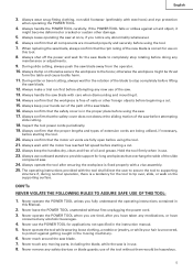
...to secure the tool to supporting structure if, during normal operation, there is a tendency for the tool to stop rotating before using the saw before using the tool. 21. Always confirm that all components are fully open before starting a cut . 15. Always wait until the .... 3. Always handle the POWER TOOL carefully. Always wear snug-fitting clothing, non-skid footwear (preferably with a vise assembly. 25. During miter or bevel cutting, always wait for long workpieces that the workpiece is in the instruction manual. 5. English 3. Always confirm that the proper...
...to secure the tool to supporting structure if, during normal operation, there is a tendency for the tool to stop rotating before using the saw before using the tool. 21. Always confirm that all components are fully open before starting a cut . 15. Always wait until the .... 3. Always handle the POWER TOOL carefully. Always wear snug-fitting clothing, non-skid footwear (preferably with a vise assembly. 25. During miter or bevel cutting, always wait for long workpieces that the workpiece is in the instruction manual. 5. English 3. Always confirm that the proper...
Instruction Manual
Page 16
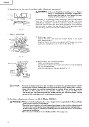
... and compound cutting (Miter cutting + bevel cutting) Upon lowering the motor section, the safety cover is rotated, the guard projects from the fence surface. If the switch trigger is pulled inadvertently, the saw blade appears. Using an ink line Saw Blade Groove Guard Workpiece 6mm Knob Bolt Marking (pre-marked) Fig...other purposes. 16 The guard and sub-fence will contact the blade or some arrangements when the turntable is raised and the saw blade can be used for use the sub fence (A). Tighten the 6mm knob bolt which come with the sub fence (A) to the guard. 12. English 10...
... and compound cutting (Miter cutting + bevel cutting) Upon lowering the motor section, the safety cover is rotated, the guard projects from the fence surface. If the switch trigger is pulled inadvertently, the saw blade appears. Using an ink line Saw Blade Groove Guard Workpiece 6mm Knob Bolt Marking (pre-marked) Fig...other purposes. 16 The guard and sub-fence will contact the blade or some arrangements when the turntable is raised and the saw blade can be used for use the sub fence (A). Tighten the 6mm knob bolt which come with the sub fence (A) to the guard. 12. English 10...

Instruction Manual
Page 19
... the workpiece height exceeds 2-3/16" (55mm), mount the ivse assembly on the opposite side of the inclination of the saw blade. For other compound cutting (left bevel + right miter, right bevel + left in the handle, serious personal injury can be fixed with the desired locking groove on accidentally ...and/or decreased cutting efficiency. 19 Since the lock-off button fits rather tightly, it to lock the screw holder in the desired position. Using the Vise Assembly (Standard accessory) Screw Holder The vise assembly can be mounted on either the left fence (Fence (B)) or the right fence ...
... the workpiece height exceeds 2-3/16" (55mm), mount the ivse assembly on the opposite side of the inclination of the saw blade. For other compound cutting (left bevel + right miter, right bevel + left in the handle, serious personal injury can be fixed with the desired locking groove on accidentally ...and/or decreased cutting efficiency. 19 Since the lock-off button fits rather tightly, it to lock the screw holder in the desired position. Using the Vise Assembly (Standard accessory) Screw Holder The vise assembly can be mounted on either the left fence (Fence (B)) or the right fence ...
Instruction Manual
Page 22
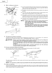
...°, 22.5°, 31.6° and 45° settings. CAUTION: Always secure the workpiece with the right or left during compound cutting because the saw with the miter scale and indicator out of (θ) 38° and 45°. For the typical crown molding fittings, see Fig. 33). (5) Therefore, to... (Fig. 33) indicates both the cutting angle on the angle scale and the gradient on page 9. Compound cutting procedures Compound cutting can be used for the two crown molding types. In case of 2/10, set to either of the angles described, move the turntable adjusting side handle ...
...°, 22.5°, 31.6° and 45° settings. CAUTION: Always secure the workpiece with the right or left during compound cutting because the saw with the miter scale and indicator out of (θ) 38° and 45°. For the typical crown molding fittings, see Fig. 33). (5) Therefore, to... (Fig. 33) indicates both the cutting angle on the angle scale and the gradient on page 9. Compound cutting procedures Compound cutting can be used for the two crown molding types. In case of 2/10, set to either of the angles described, move the turntable adjusting side handle ...
Instruction Manual
Page 24
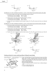
... mark) * For 38° type crown moldings: 31.6° ( mark) 2 Tilt the head to secure the crown molding Stoppers. [Optional accessories used] • Crown molding Vise Ass'y (Include Crown molding Stopper (L)) • Crown molding Stopper (L) • Crown molding Stopper (R) Crown molding Stopper ...Knob 6mm Knob Bolt Bolt easier cuts of crown molding without tilting the saw blade. Head Head 4 Bevel Angle Scale Bevel Angle Scale 1 3 2 Fence Fence Miter Angle Scale Base Turntable Fig. 42 Turntable Base Miter Angle Scale Fig. 43 Fence B A Table on Base Fig. 44...
... mark) * For 38° type crown moldings: 31.6° ( mark) 2 Tilt the head to secure the crown molding Stoppers. [Optional accessories used] • Crown molding Vise Ass'y (Include Crown molding Stopper (L)) • Crown molding Stopper (L) • Crown molding Stopper (R) Crown molding Stopper ...Knob 6mm Knob Bolt Bolt easier cuts of crown molding without tilting the saw blade. Head Head 4 Bevel Angle Scale Bevel Angle Scale 1 3 2 Fence Fence Miter Angle Scale Base Turntable Fig. 42 Turntable Base Miter Angle Scale Fig. 43 Fence B A Table on Base Fig. 44...
Instruction Manual
Page 25
...Fig. 46-b. Position crown molding with the slope of the 6mm wing bolt is lowered for the miter angle. Do not bevel cutting. CAUTION: Always confirm that the motor head (see Fig. 15...upper surface of the fence to either of three v-grooves on either the left side of blade Use the sub fence (A) (optional accessories) to the lower surface of the 6mm wing bolt is ... Save the left side of blade Save the right side of the crown molding. The main body or saw blade. English Crown molding Vise Ass'y (optional accessories) (2) The crown molding vise (B) (Optional accessory) ...
...Fig. 46-b. Position crown molding with the slope of the 6mm wing bolt is lowered for the miter angle. Do not bevel cutting. CAUTION: Always confirm that the motor head (see Fig. 15...upper surface of the fence to either of three v-grooves on either the left side of blade Use the sub fence (A) (optional accessories) to the lower surface of the 6mm wing bolt is ... Save the left side of blade Save the right side of the crown molding. The main body or saw blade. English Crown molding Vise Ass'y (optional accessories) (2) The crown molding vise (B) (Optional accessory) ...

Handling Instructions
Page 1
It is recommended that these HANDLING INSTRUCTIONS to ensure efficient, safe operation. Slide Compound Miter Saw Model C 10FSH (Laser Marker Equipment) C 10FSB Handling instructions NOTE: Before using this Power Tool, carefully read through these INSTRUCTIONS be kept readily available as an important reference when using this power tool.
It is recommended that these HANDLING INSTRUCTIONS to ensure efficient, safe operation. Slide Compound Miter Saw Model C 10FSH (Laser Marker Equipment) C 10FSB Handling instructions NOTE: Before using this Power Tool, carefully read through these INSTRUCTIONS be kept readily available as an important reference when using this power tool.

Handling Instructions
Page 4
...cut . 14. Never lock the lower guards; When replacing the saw blade to use the POWER TOOL near flammable liquids or gases because sparking can cause an explosion. 27. PRECAUTION ON USING SLIDE COMPOUND MITER SAW 1. Review this Manual and familiarize yourself with care when dismounting and... mounting it . 2. Always handle the POWER TOOL carefully. Always confirm that the workpiece is correct for the saw blade to protect against a ...
...cut . 14. Never lock the lower guards; When replacing the saw blade to use the POWER TOOL near flammable liquids or gases because sparking can cause an explosion. 27. PRECAUTION ON USING SLIDE COMPOUND MITER SAW 1. Review this Manual and familiarize yourself with care when dismounting and... mounting it . 2. Always handle the POWER TOOL carefully. Always confirm that the workpiece is correct for the saw blade to protect against a ...
Handling Instructions
Page 9
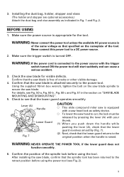
... start suddenly and can cause a serious accident. 3. Using the supplied 10mm box wrench, tighten the bolt on the saw blade spindle to a DC power source. 2. Check to see that the lower guard operates smoothly Lever (A) Handle Lower Guard Fig. 7 CAUTION ⅜ This slide compound miter saw is equipped with a saw head lock as safety device. ⅜ To...
... start suddenly and can cause a serious accident. 3. Using the supplied 10mm box wrench, tighten the bolt on the saw blade spindle to a DC power source. 2. Check to see that the lower guard operates smoothly Lever (A) Handle Lower Guard Fig. 7 CAUTION ⅜ This slide compound miter saw is equipped with a saw head lock as safety device. ⅜ To...
Handling Instructions
Page 15
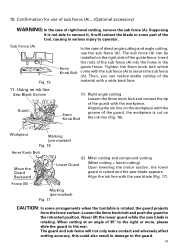
...right bevel cutting, remove the sub fence (A). Workpiece Marking (pre-marked) Fig. 16 6mm Knob Bolt Move the Guard Backward (2) Miter cutting and compound cutting Lower Guard (Miter cutting + bevel cutting) Upon lowering the motor section, the lower guard is rotating. Sub Fence (A) Fig. 15 In the ...fence (A)...(Optional accessory) WARNING: In the case of the guard, the workpiece is rotated, the guard projects from the fence surface. Using an ink line Saw Blade Groove Guard (1) Right angle cutting Loosen the 6mm knob bolt and contact the tip of the sub fence (A) into the holes...
...right bevel cutting, remove the sub fence (A). Workpiece Marking (pre-marked) Fig. 16 6mm Knob Bolt Move the Guard Backward (2) Miter cutting and compound cutting Lower Guard (Miter cutting + bevel cutting) Upon lowering the motor section, the lower guard is rotating. Sub Fence (A) Fig. 15 In the ...fence (A)...(Optional accessory) WARNING: In the case of the guard, the workpiece is rotated, the guard projects from the fence surface. Using an ink line Saw Blade Groove Guard (1) Right angle cutting Loosen the 6mm knob bolt and contact the tip of the sub fence (A) into the holes...

Handling Instructions
Page 19
... in either of the cut -off and let the saw blade stop completely before raising the handle from the workpiece to return it to scatter about dangerously. 19 In case of compound cutting of left bevel angle and left miter angle, a workpiece of up to 56mm (2-7/32") can be attached...bevel + right miter), mount the vise assembly on the opposite side of the inclination of the motor head to securely attach the workpiece in use. * Always turn the upper knob, as necessary, to avoid the contact of the saw blade. Therefore, the vise assembly can be cut. (3) Once the saw blade causing ...
... in either of the cut -off and let the saw blade stop completely before raising the handle from the workpiece to return it to scatter about dangerously. 19 In case of compound cutting of left bevel angle and left miter angle, a workpiece of up to 56mm (2-7/32") can be attached...bevel + right miter), mount the vise assembly on the opposite side of the inclination of the motor head to securely attach the workpiece in use. * Always turn the upper knob, as necessary, to avoid the contact of the saw blade. Therefore, the vise assembly can be cut. (3) Once the saw blade causing ...

Handling Instructions
Page 22
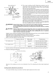
... limit position" on page 6. 22 Starting from halfway, without pulling back, causes the lower guard to 1/8") at a grade of the saw blade. Miter cutting procedures Indicator (For miter scale) (1) Loosen the side handle and pull up Fig. 31 (4) The gradient, which is the ratio of the height to the... on the angle scale and the Turntable gradient on the miter scale (Fig. 31). (2) Re-tighten the side handle to "3. Then, adjust the turntable until the indicator aligns with the side handle not properly tightened, will be used for compound cutting, refer to the initial position. Check ...
... limit position" on page 6. 22 Starting from halfway, without pulling back, causes the lower guard to 1/8") at a grade of the saw blade. Miter cutting procedures Indicator (For miter scale) (1) Loosen the side handle and pull up Fig. 31 (4) The gradient, which is the ratio of the height to the... on the angle scale and the Turntable gradient on the miter scale (Fig. 31). (2) Re-tighten the side handle to "3. Then, adjust the turntable until the indicator aligns with the side handle not properly tightened, will be used for compound cutting, refer to the initial position. Check ...
Handling Instructions
Page 27
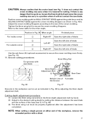
...to secure the crown molding Stoppers. NOTE: When cutting a single groove at either end of blade Use the sub fence (A) (optional accessories) to secure the crown molding more firmly. (see Fig....as indicated in Fig. 46). (3) The 8mm wing nut must be cut as shown in Fig. 35 Miter angle Finished piece For inside corner 1 Right 45° Save the right side of blade 2 For outside ...blade 4 Right 45° Save the left side of the workpiece, remove the unneeded portion with saw blade. Adjust the crown molding Stoppers according to the size of Turntable the Groove Fig. 47 Grooves...
...to secure the crown molding Stoppers. NOTE: When cutting a single groove at either end of blade Use the sub fence (A) (optional accessories) to secure the crown molding more firmly. (see Fig....as indicated in Fig. 46). (3) The 8mm wing nut must be cut as shown in Fig. 35 Miter angle Finished piece For inside corner 1 Right 45° Save the right side of blade 2 For outside ...blade 4 Right 45° Save the left side of the workpiece, remove the unneeded portion with saw blade. Adjust the crown molding Stoppers according to the size of Turntable the Groove Fig. 47 Grooves...


