
Instruction Manual
Page 6
...handle can cause hearing loss. 3. ALWAYS wear ear protectors when using the tool for the screw diameter. 4. Employ a driver bit appropriate for extended periods. NEVER operate without all screws, bolts and covers tightly in proper working order. Don't force small tool or attachment to ... and in place. Blades and accessories must be sure to electric shock. Prevent potential injuries to a screw head when driving a screw. 5. NEVER operate this tool without all screws, bolts, and plates tightly mounted. Operate the tool according to the tool. If maintenance or servicing ...
...handle can cause hearing loss. 3. ALWAYS wear ear protectors when using the tool for the screw diameter. 4. Employ a driver bit appropriate for extended periods. NEVER operate without all screws, bolts and covers tightly in proper working order. Don't force small tool or attachment to ... and in place. Blades and accessories must be sure to electric shock. Prevent potential injuries to a screw head when driving a screw. 5. NEVER operate this tool without all screws, bolts, and plates tightly mounted. Operate the tool according to the tool. If maintenance or servicing ...

Instruction Manual
Page 9
...-Load Speed 0-6000/min. 0-4500/min. 0-3000/min. 0-2600/min. 0-1700/min. NEVER operate, or attempt any maintenance on your own power tool. Capacity Drywall screw 3/16" (5 mm) Self-drilling screw 1/4" (6 mm) 1/4" (6 mm) 5/16" (8 mm) Weight 3.1 lbs (1.4 kg) 3.3 lbs (1.5 kg) 9
...-Load Speed 0-6000/min. 0-4500/min. 0-3000/min. 0-2600/min. 0-1700/min. NEVER operate, or attempt any maintenance on your own power tool. Capacity Drywall screw 3/16" (5 mm) Self-drilling screw 1/4" (6 mm) 1/4" (6 mm) 5/16" (8 mm) Weight 3.1 lbs (1.4 kg) 3.3 lbs (1.5 kg) 9
Instruction Manual
Page 10
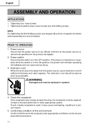
.... 3. Power source Ensure that the work area is used, it may cause overheating, resulting in a serious hazard. 5. head screws ⅜ Tightening Drywall screws, wood screws and self-drilling screws NOTE: For tightening the Self-drilling screws, sub-stopper (B) and non-magnetic bit holder (sold separately) are recommended. PRIOR TO OPERATION 1. WARNING: Damaged cord must be...
.... 3. Power source Ensure that the work area is used, it may cause overheating, resulting in a serious hazard. 5. head screws ⅜ Tightening Drywall screws, wood screws and self-drilling screws NOTE: For tightening the Self-drilling screws, sub-stopper (B) and non-magnetic bit holder (sold separately) are recommended. PRIOR TO OPERATION 1. WARNING: Damaged cord must be...

Instruction Manual
Page 11
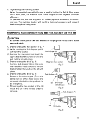
...left with click feeling. (1) For hex-head screws (Fig. 4) Mount a hex-head screw on the hexsocket and set the distance between the sub-stopper end and the screw head neck to 0.04" - 0.06" (1 - 1.5 mm). (2) For drywall screws (Fig. 5) Mount a drywall screw on the bit, and set the distance between... the sub-stopper end and the screw head to 0.06" - 0.07" (1.5 - 2 mm). (3) For cross-recessed self-drilling screws (Fig. 6) Mount a self-drilling screw on the bit, and set to the "L" side position, the bit rotates counterclockwise and can be used to 0.04" - 0.06...
...left with click feeling. (1) For hex-head screws (Fig. 4) Mount a hex-head screw on the hexsocket and set the distance between the sub-stopper end and the screw head neck to 0.04" - 0.06" (1 - 1.5 mm). (2) For drywall screws (Fig. 5) Mount a drywall screw on the bit, and set the distance between... the sub-stopper end and the screw head to 0.06" - 0.07" (1.5 - 2 mm). (3) For cross-recessed self-drilling screws (Fig. 6) Mount a self-drilling screw on the bit, and set to the "L" side position, the bit rotates counterclockwise and can be used to 0.04" - 0.06...

Instruction Manual
Page 12
... trigger switch is held at an angle, the driving force will then remain ON even when the finger is set to the "R" side position. English 8. Screw Driver operation When the switch is running. Attach the hex-socket to run but the hex-socket (or the bit) does not rotate. The hex...-socket then rotates and tightens the screw. To facilitate continuous operation, pull the trigger switch and depress the switch stopper. Direction of hex-socket (or bit holder) rotation while the motor is...
... trigger switch is held at an angle, the driving force will then remain ON even when the finger is set to the "R" side position. English 8. Screw Driver operation When the switch is running. Attach the hex-socket to run but the hex-socket (or the bit) does not rotate. The hex...-socket then rotates and tightens the screw. To facilitate continuous operation, pull the trigger switch and depress the switch stopper. Direction of hex-socket (or bit holder) rotation while the motor is...
Instruction Manual
Page 13
...Mounting the hex-socket or the bit Install the bit in the magnet bit will prevent the bushing from being worn. Tightening Self-drilling screw When the supplied magnet bit holder is recommended. MOUNTING AND DISMOUNTING THE HEX-SOCKET OR THE BIT CAUTION Be sure to Bit Bit holder...9 13 The stainless locator with pliers. 4. To prevent this, the non-magnetic bit holder (optional accessory) is used to tighten the Self-drilling screw into a steel plate, cut material stuck in the reverse order to switch power OFF and disconnect the plug from the locator. English 4. Dismounting the...
...Mounting the hex-socket or the bit Install the bit in the magnet bit will prevent the bushing from being worn. Tightening Self-drilling screw When the supplied magnet bit holder is recommended. MOUNTING AND DISMOUNTING THE HEX-SOCKET OR THE BIT CAUTION Be sure to Bit Bit holder...9 13 The stainless locator with pliers. 4. To prevent this, the non-magnetic bit holder (optional accessory) is used to tighten the Self-drilling screw into a steel plate, cut material stuck in the reverse order to switch power OFF and disconnect the plug from the locator. English 4. Dismounting the...

Instruction Manual
Page 14
...from the receptacle during maintenance and inspection. 1. Cleaning the unit exterior Wipe off oil and stain on this screw driver with the tool to the Hitachi Authorized Service Center when requesting repair or other maintenance. To assure that they are properly tightened. B: Code... this tool should ONLY be performed by a Hitachi Authorized Service Center. Used D: Remarks CAUTION: Repair, modification and inspection of Hitachi Power Tools must be performed by a Hitachi Authorized Service Center. 6. This Parts List will damage screw heads, replace the hex. English MAINTENANCE AND ...
...from the receptacle during maintenance and inspection. 1. Cleaning the unit exterior Wipe off oil and stain on this screw driver with the tool to the Hitachi Authorized Service Center when requesting repair or other maintenance. To assure that they are properly tightened. B: Code... this tool should ONLY be performed by a Hitachi Authorized Service Center. Used D: Remarks CAUTION: Repair, modification and inspection of Hitachi Power Tools must be performed by a Hitachi Authorized Service Center. 6. This Parts List will damage screw heads, replace the hex. English MAINTENANCE AND ...

Instruction Manual
Page 16
English OPTIONAL ACCESSORIES ...........sold separately 1. For other screws Screw head Type Bit Size No.1 No.2 No.3 No.1 No.2 No.1 No.2 No.3 No.1 No.2 Code No. 985333 971511Z 971512Z 985334 985335 985336 985337 985338...bit bolder (Code No. 982563Z) 3. H 1/4 985328 H 5/16 985327 H 3/8 985326 Size H 1/4 H 5/16 H 3/8 2. H 1/4 985332 H 5/16 985322 H 3/8 985330 Non magnetic type Size Code No. For hex-head screws Hex-socket Sub-Stopper (B) Magnetic type Size Code No. Plastic case (Code No. 310504) Code No. 317827 317671 317670 Sub-Stopper Sub-Stopper (G) (Code No...
English OPTIONAL ACCESSORIES ...........sold separately 1. For other screws Screw head Type Bit Size No.1 No.2 No.3 No.1 No.2 No.1 No.2 No.3 No.1 No.2 Code No. 985333 971511Z 971512Z 985334 985335 985336 985337 985338...bit bolder (Code No. 982563Z) 3. H 1/4 985328 H 5/16 985327 H 3/8 985326 Size H 1/4 H 5/16 H 3/8 2. H 1/4 985332 H 5/16 985322 H 3/8 985330 Non magnetic type Size Code No. For hex-head screws Hex-socket Sub-Stopper (B) Magnetic type Size Code No. Plastic case (Code No. 310504) Code No. 317827 317671 317670 Sub-Stopper Sub-Stopper (G) (Code No...
Parts List
Page 1
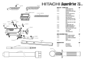
... LIST - 75 SERIES TOOL QTY 725414 MODULE (GREEN DOT) 1 725415 SPRING (GREEN) 1.7mm 1 725413 NOSEPIECE FLAT HEAD SCREW M4x10mm 1 725470 NOSEPIECE SUBFLOOR AND METAL-TO-METAL 1 725471 NOSEPIECE DECK/DRYWALL 1 725425 END PLATE FOR 75 1 725424 WING... SCREW FOR END PLATE 1 725423 BODY HEX SOCKET CAP SCREW M4x8 1 725422 BODY HEX SOCKET CAP SCREW M4x10 2 725416 RETAINER SCREW - M3x6 2 725416 RETAINER FOR MODULE 3mm 2 725427 BRACKET FOR FEEDTRACK 2 725428 FEED TRACK...
... LIST - 75 SERIES TOOL QTY 725414 MODULE (GREEN DOT) 1 725415 SPRING (GREEN) 1.7mm 1 725413 NOSEPIECE FLAT HEAD SCREW M4x10mm 1 725470 NOSEPIECE SUBFLOOR AND METAL-TO-METAL 1 725471 NOSEPIECE DECK/DRYWALL 1 725425 END PLATE FOR 75 1 725424 WING... SCREW FOR END PLATE 1 725423 BODY HEX SOCKET CAP SCREW M4x8 1 725422 BODY HEX SOCKET CAP SCREW M4x10 2 725416 RETAINER SCREW - M3x6 2 725416 RETAINER FOR MODULE 3mm 2 725427 BRACKET FOR FEEDTRACK 2 725428 FEED TRACK...
Operating Instructions
Page 1
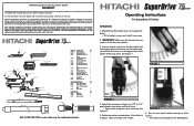
... END PLATE 1 725423 BODY HEX SOCKET CAP SCREW M4x8 1 725422 BODY HEX SOCKET CAP SCREW M4x10 2 725416 RETAINER SCREW - Appx. 1/4" FIGURE 1. 4. Adjust the nosepiece so there is in the forward position. 3. SuperDrive makes no responsibility whatsoever for replacement parts. IMPORTANT! See Figure 2. 5. HITACHI SuperDrive Auto-feed Screw System WARRANTY HITACHI SuperDrive tools and system components are made. FIGURE 2. No other warranties...
... END PLATE 1 725423 BODY HEX SOCKET CAP SCREW M4x8 1 725422 BODY HEX SOCKET CAP SCREW M4x10 2 725416 RETAINER SCREW - Appx. 1/4" FIGURE 1. 4. Adjust the nosepiece so there is in the forward position. 3. SuperDrive makes no responsibility whatsoever for replacement parts. IMPORTANT! See Figure 2. 5. HITACHI SuperDrive Auto-feed Screw System WARRANTY HITACHI SuperDrive tools and system components are made. FIGURE 2. No other warranties...

Operating Instructions
Page 2
...to electric tools should be performed only by loosening the screws and pushing in the tool. Screws are turning but not driving at all . 1. Be sure the screwgun is worn and must be pushed back and taken out. 2. Operating the SuperDrive too fast. 3. Strip is broken and the end...the feed track. 7. If damaged have the tool serviced by first unplugging screwgun from LOX, Phillips or Square Drive fasteners. 2. Screws are being skipped. Not lifting the SuperDrive off before starting . Do not use if parts stick. 3. Be sure switch is worn and must be replaced. A wrench or...
...to electric tools should be performed only by loosening the screws and pushing in the tool. Screws are turning but not driving at all . 1. Be sure the screwgun is worn and must be pushed back and taken out. 2. Operating the SuperDrive too fast. 3. Strip is broken and the end...the feed track. 7. If damaged have the tool serviced by first unplugging screwgun from LOX, Phillips or Square Drive fasteners. 2. Screws are being skipped. Not lifting the SuperDrive off before starting . Do not use if parts stick. 3. Be sure switch is worn and must be replaced. A wrench or...