Owners Manual
Page 3
...damages caused by other product, such as EMC standard EN55022 (corresponding to FCC part 15 Class B, etc.). Hitachi's liability may be responsible for a complete statement of warranty rights, remedies and limitation of data stored on ...meets the following cases require a system side improvement for products which have been changed by anyone else. HITACHIɹSHALL NOT BE LIABLE FOR ANY SPECIAL, INCIDENTAL OR CONSEQUENTIAL DAMAGES, EVEN IF INFORMED OF THE ...950-M95 - However, anything other than this product, such as an interface cable, is sold with its sales contact.
...damages caused by other product, such as EMC standard EN55022 (corresponding to FCC part 15 Class B, etc.). Hitachi's liability may be responsible for a complete statement of warranty rights, remedies and limitation of data stored on ...meets the following cases require a system side improvement for products which have been changed by anyone else. HITACHIɹSHALL NOT BE LIABLE FOR ANY SPECIAL, INCIDENTAL OR CONSEQUENTIAL DAMAGES, EVEN IF INFORMED OF THE ...950-M95 - However, anything other than this product, such as an interface cable, is sold with its sales contact.
Owners Manual
Page 4
... occur. 8. It may cause bodily injury. K6602705 Rev.3 08.20.01 - 4 - Do not make contact with care. 6. Handle with the interface connector pins. Safety Instructions Caution 1. Do not hit the interface connector pins against other applications that pose a significant risk of the HDD may cause catastrophic failures. 17. Since reliability and product...
... occur. 8. It may cause bodily injury. K6602705 Rev.3 08.20.01 - 4 - Do not make contact with care. 6. Handle with the interface connector pins. Safety Instructions Caution 1. Do not hit the interface connector pins against other applications that pose a significant risk of the HDD may cause catastrophic failures. 17. Since reliability and product...
Owners Manual
Page 6
... 4.2.2 Single HDD Test Condition 4.2.3 Attention for HDD Installation 4.3 Drive Address Setting(DRIVE 0/DRIVE 1) 4.4 Dimensions 5.0 Packing and Handling 5.1 Packing 5.2 Handling 6.0 Interface 6.1 Power Interface 6.2 Physical Interface 6.2.1 Connector 6.2.2 Connector Pin Assignment 6.2.3 Description of the Interface Signals 6.3 Logical Interface 6.3.1 I/O Registers 6.3.1.1 Data Register 6.3.1.2 Error Register 6.3.1.3 Features Register 6.3.1.4 Sector Count Register 6.3.1.5 Sector Number Register 6.3.1.6 Cylinder Low Register 6.3.1.7 Cylinder High Register 6.3.1.8 Device...
... 4.2.2 Single HDD Test Condition 4.2.3 Attention for HDD Installation 4.3 Drive Address Setting(DRIVE 0/DRIVE 1) 4.4 Dimensions 5.0 Packing and Handling 5.1 Packing 5.2 Handling 6.0 Interface 6.1 Power Interface 6.2 Physical Interface 6.2.1 Connector 6.2.2 Connector Pin Assignment 6.2.3 Description of the Interface Signals 6.3 Logical Interface 6.3.1 I/O Registers 6.3.1.1 Data Register 6.3.1.2 Error Register 6.3.1.3 Features Register 6.3.1.4 Sector Count Register 6.3.1.5 Sector Number Register 6.3.1.6 Cylinder Low Register 6.3.1.7 Cylinder High Register 6.3.1.8 Device...

Owners Manual
Page 8
... 6.3.2.11.3 Device Configuration Identify [B1h, Sub 02h] 89 6.3.2.11.4 Device Configuration Set [B1h, Sub 03h] 91 6.3.2.12 Note for Write Cache and Auto Reallocation 95 6.4 Interface Signal Timing 96 6.4.1 Data Transfer Timing 96 6.4.2 Ultra DMA Data Transfer Timing 99 6.4.3 Power On and Hardware Reset Timing 109 < Glossary > 110 < Reference > 111 K6602705...
... 6.3.2.11.3 Device Configuration Identify [B1h, Sub 02h] 89 6.3.2.11.4 Device Configuration Set [B1h, Sub 03h] 91 6.3.2.12 Note for Write Cache and Auto Reallocation 95 6.4 Interface Signal Timing 96 6.4.1 Data Transfer Timing 96 6.4.2 Ultra DMA Data Transfer Timing 99 6.4.3 Power On and Hardware Reset Timing 109 < Glossary > 110 < Reference > 111 K6602705...

Owners Manual
Page 9
...type form factor by applying the latest high-density recording technology. Read-ahead Cache/Write Cache - Load/Unload Mechanism - 95 grams(DK23DA-40F/30F)/91 grams(DK23DA-20F/10F) - Word 60Ŋ61 Total LBA 78140160 (04A85300h) 58605120 (037E3E40h) 39070080 (02542980h) 19640880 (012BB230h) K6602705 Rev.3 08...fly ECC Correction - GMR Head - Non-operating Shock 7,840m/S2(800G, 1ms, half-sine wave) - Capacity Model (Formatted) Height Interface DK23DA-40F DK23DA-30F DK23DA-20F DK23DA-10F 40.007 GB 30.005 GB 20.003 GB 10.056 GB 9.5 mm 9.5 mm 9.5 mm 9.5 mm ATA-5(IDE) ATA...
...type form factor by applying the latest high-density recording technology. Read-ahead Cache/Write Cache - Load/Unload Mechanism - 95 grams(DK23DA-40F/30F)/91 grams(DK23DA-20F/10F) - Word 60Ŋ61 Total LBA 78140160 (04A85300h) 58605120 (037E3E40h) 39070080 (02542980h) 19640880 (012BB230h) K6602705 Rev.3 08...fly ECC Correction - GMR Head - Non-operating Shock 7,840m/S2(800G, 1ms, half-sine wave) - Capacity Model (Formatted) Height Interface DK23DA-40F DK23DA-30F DK23DA-20F DK23DA-10F 40.007 GB 30.005 GB 20.003 GB 10.056 GB 9.5 mm 9.5 mm 9.5 mm 9.5 mm ATA-5(IDE) ATA...

Owners Manual
Page 13
...Sleep/Standby - DK23DA- 40F 30F 20F 10F 1 Capacity per drive (Formatted) Capacity per sector Disks Heads Cylinders 2 Seek time Average (Nominal Maximum value) Minimum 3 Average latency Disk rotational speed 4 Recording density Track density Recording method 5 Interface Data transfer rate ...Low Power Active *7 0.33 A(1.65W) -Seek *8 0.45 A(2.25W) - Start up *5 0.90 A(4.5W) - Read/Write *9 0.40/0.40 A(2.0/2.0W) - DK23DA- DK23DA- Ready *2 7 DimensionsʢWʷHʷD) Max. 100 (Ultra DMA mode 5) 2,048 5 (Typical) *3 3 (Typical) *3 70Wʷ9.5Hʷ100D ...
...Sleep/Standby - DK23DA- 40F 30F 20F 10F 1 Capacity per drive (Formatted) Capacity per sector Disks Heads Cylinders 2 Seek time Average (Nominal Maximum value) Minimum 3 Average latency Disk rotational speed 4 Recording density Track density Recording method 5 Interface Data transfer rate ...Low Power Active *7 0.33 A(1.65W) -Seek *8 0.45 A(2.25W) - Start up *5 0.90 A(4.5W) - Read/Write *9 0.40/0.40 A(2.0/2.0W) - DK23DA- DK23DA- Ready *2 7 DimensionsʢWʷHʷD) Max. 100 (Ultra DMA mode 5) 2,048 5 (Typical) *3 3 (Typical) *3 70Wʷ9.5Hʷ100D ...
Owners Manual
Page 16
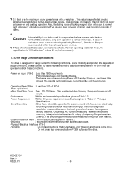
... be less than 50 mAp-p (Frequency Range: less than 500mVp-p. *4 :3.9 Bels are the maximum sound power levels with recommended screws and regular torque. -Physical/Electrical Interface: ATA-5 -Handling : Do not add Electrical Static Discharge, and Vibration and Shock to compromise the host system data backup. This value is not recommended. In...
... be less than 50 mAp-p (Frequency Range: less than 500mVp-p. *4 :3.9 Bels are the maximum sound power levels with recommended screws and regular torque. -Physical/Electrical Interface: ATA-5 -Handling : Do not add Electrical Static Discharge, and Vibration and Shock to compromise the host system data backup. This value is not recommended. In...

Owners Manual
Page 21
... If all of pins A,B, D are open, the drive is DRIVE 0(or single). 4.2.3 Attention for HDD Installation Caution (1) In case of steel plate installation on the interface connector by the condition of CSEL signal (pin# 28). (Recommended type of jumper socket) Vender: IRISO ELECTRONICS CO., LTD. If the insulation is determined by...
... If all of pins A,B, D are open, the drive is DRIVE 0(or single). 4.2.3 Attention for HDD Installation Caution (1) In case of steel plate installation on the interface connector by the condition of CSEL signal (pin# 28). (Recommended type of jumper socket) Vender: IRISO ELECTRONICS CO., LTD. If the insulation is determined by...

Owners Manual
Page 25
6.0 Interface 6.1 Power Interface Only +5VDC power is applied to this Device. Figures 6-1 and 6-2 show power current transitions after turning on the power. Typical Spin-up Current Transition 1.6 Current ...
6.0 Interface 6.1 Power Interface Only +5VDC power is applied to this Device. Figures 6-1 and 6-2 show power current transitions after turning on the power. Typical Spin-up Current Transition 1.6 Current ...

Owners Manual
Page 26
6.2 Physical Interface 6.2.1 Connector This device has a 2mm pitch interface connector which contains a power line. Interface cable side Drive side Table 6.1 Connector Parts List Name Signal Connector Receptacle Parts number of recommended type Molex 87259-4413 or equivalent Cable Signal Connector Plug AWG#28 or equivalent Molex 87400-5005 or equivalent 3.86 mm 2 mm K6602705 Rev.3 08.20.01 2 mm PIN1 PINS REMOVED(KEY) PIN44 PIN20 REMOVED(KEY) Figure 6-3 Connector Location - 26 - The connector location is shown in Figure 6-3.
6.2 Physical Interface 6.2.1 Connector This device has a 2mm pitch interface connector which contains a power line. Interface cable side Drive side Table 6.1 Connector Parts List Name Signal Connector Receptacle Parts number of recommended type Molex 87259-4413 or equivalent Cable Signal Connector Plug AWG#28 or equivalent Molex 87400-5005 or equivalent 3.86 mm 2 mm K6602705 Rev.3 08.20.01 2 mm PIN1 PINS REMOVED(KEY) PIN44 PIN20 REMOVED(KEY) Figure 6-3 Connector Location - 26 - The connector location is shown in Figure 6-3.

Owners Manual
Page 28
...not ready to respond to be left unconnected. O This signal is used for register access other than data register. 6.2.3 Description of the Interface Signals The interface is a flow control signal for Ultra DMA Write. "I" of I The rising edge of this Write Strobe signal clocks data from a ... D rive address GND 0 OPEN 1 ççç*1: Signal name in Figure 6-4 and Table 6.2. This signal is a flow control signal for interface logic circuit. Both the rising and falling edge latch the data from DD(15:0) into the host. This signal is Write data strobe signal from...
...not ready to respond to be left unconnected. O This signal is used for register access other than data register. 6.2.3 Description of the Interface Signals The interface is a flow control signal for Ultra DMA Write. "I" of I The rising edge of this Write Strobe signal clocks data from a ... D rive address GND 0 OPEN 1 ççç*1: Signal name in Figure 6-4 and Table 6.2. This signal is a flow control signal for interface logic circuit. Both the rising and falling edge latch the data from DD(15:0) into the host. This signal is Write data strobe signal from...

Owners Manual
Page 31
6.3 Logical Interface 6.3.1 I /O registers. The registers are used for transferring data blocks between the host system and the device is done through I /O Registers Communication between the HDD's data ...
6.3 Logical Interface 6.3.1 I /O registers. The registers are used for transferring data blocks between the host system and the device is done through I /O Registers Communication between the HDD's data ...

Owners Manual
Page 32
...Aborted Command): This bit indicates that execution of the Recalibrate command. e) UNC(Uncorrectable Data Error): This bit indicates that an interface CRC error was occurred. This bit is not applied for any disk access. When a command has been completed and the ...contains the starting cylinder address for any disk access. IDNF - In LBA mode, this register displays the currently specified cylinder number. f) ICRC(Interface CRC Error): This bit indicates that an uncorrectable error has occurred. This definition cannot be from 1 to all commands. For more information on...
...Aborted Command): This bit indicates that execution of the Recalibrate command. e) UNC(Uncorrectable Data Error): This bit indicates that an interface CRC error was occurred. This bit is not applied for any disk access. When a command has been completed and the ...contains the starting cylinder address for any disk access. IDNF - In LBA mode, this register displays the currently specified cylinder number. f) ICRC(Interface CRC Error): This bit indicates that an uncorrectable error has occurred. This definition cannot be from 1 to all commands. For more information on...

Owners Manual
Page 40
... Number Bit 15 - 6 Reserved for ATA-6 - 14 Bit 5 1 = Supports ATA-5 Bit 4 1 = Supports ATA-4 Bit 3 1 = Supports ATA-3 Bit 2 1 = Supports ATA-2 Bit 1 Obsolete Bit 0 Reserved 81 ATA Interface Minor Version Number 82 Command Set Supported 0000h or FFFFh = Command set notification not supported Bit 15 0 = Reserved Bit 14 1 = NOP command supported Bit 13...
... Number Bit 15 - 6 Reserved for ATA-6 - 14 Bit 5 1 = Supports ATA-5 Bit 4 1 = Supports ATA-4 Bit 3 1 = Supports ATA-3 Bit 2 1 = Supports ATA-2 Bit 1 Obsolete Bit 0 Reserved 81 ATA Interface Minor Version Number 82 Command Set Supported 0000h or FFFFh = Command set notification not supported Bit 15 0 = Reserved Bit 14 1 = NOP command supported Bit 13...
Owners Manual
Page 54
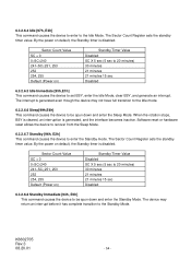
The Sector Count Register sets the standby timer value. By the power on default, the Standby timer is disabled. Sector Count Value SC = 0 0 6.3.2.6.4 Idle [97h, E3h] This command causes the device to enter to the Idle Mode.
The Sector Count Register sets the standby timer value. By the power on default, the Standby timer is disabled. Sector Count Value SC = 0 0 6.3.2.6.4 Idle [97h, E3h] This command causes the device to enter to the Idle Mode.
Owners Manual
Page 96
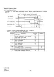
... To IOCS16- Data Hold 5 t6Z DIOR- Negation (MAX) t9 DIOR-/DIOW- to DIOR-/DIOW- Setup 25 t2 DIOR-/DIOW- 6.4 Interface Signal Timing 6.4.1 Data Transfer Timing Figures 6-4, 6-5, and 6-7 show the timing for asserting interface signals for transferring 16-bit and 8-bit data. Recovery 25 t3 DIOW- Data Setup 20 t6 DIOR- Figure 6-4 PIO...
... To IOCS16- Data Hold 5 t6Z DIOR- Negation (MAX) t9 DIOR-/DIOW- to DIOR-/DIOW- Setup 25 t2 DIOR-/DIOW- 6.4 Interface Signal Timing 6.4.1 Data Transfer Timing Figures 6-4, 6-5, and 6-7 show the timing for asserting interface signals for transferring 16-bit and 8-bit data. Recovery 25 t3 DIOW- Data Setup 20 t6 DIOR- Figure 6-4 PIO...
Owners Manual
Page 110
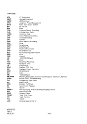
... Drive Seek Complete Drive Write Fault Error Checking and Correction Error Ground 1000,000,000 bytes Head Head/Disk Assembly Hard Disk Drive Input/Output Interface CRC Error Intelligent Device Electronics ID Not Found Index 1000,000 bytes Modified, Extended, Extended Partial Response Maximum Likelihood Printed Circuit Board Assembly Programmed Input...
... Drive Seek Complete Drive Write Fault Error Checking and Correction Error Ground 1000,000,000 bytes Head Head/Disk Assembly Hard Disk Drive Input/Output Interface CRC Error Intelligent Device Electronics ID Not Found Index 1000,000 bytes Modified, Extended, Extended Partial Response Maximum Likelihood Printed Circuit Board Assembly Programmed Input...