Owners Manual
Page 4
... to this manual. Voltage rise time 5 - 100 ms at power off. 11. Prevent shocks, which is required for the disk platter, opening of the HDD may cause catastrophic failures. 17. Dropping of Metal Head Disk Assembly (HDA) may contact to the connector insertion or jumper setting can damage the drive. Handle with any material, it may occur. 8. Since the drive uses glass media for power supply. Label or...
... to this manual. Voltage rise time 5 - 100 ms at power off. 11. Prevent shocks, which is required for the disk platter, opening of the HDD may cause catastrophic failures. 17. Dropping of Metal Head Disk Assembly (HDA) may contact to the connector insertion or jumper setting can damage the drive. Handle with any material, it may occur. 8. Since the drive uses glass media for power supply. Label or...

Owners Manual
Page 8
...13 SMART Write Log Sector [B0h, Sub D6h] 70 6.3.2.9 Security Mode Feature 71 6.3.2.9.1 Security Mode Default Setting 71 6.3.2.9.2 Initial Setting of the User Password 72 6.3.2.9.3 Security Mode Operation from Power-on or Hardware Reset 72 6.3.2.9.4 User Password Lost 73 6.3.2.9.5 Security Set Password [F1h] 74 6.3.2.9.6 Security Unlock [F2h] 75 6.3.2.9.7 Security Erase Prepare [F3h] 76 6.3.2.9.8 Security Erase Unit [F4h] 76 6.3.2.9.9 Security Freeze Lock [F5h] 77 6.3.2.9.10 Security Disable Password [F6h] 77 6.3.2.9.11 Security Mode Command Action...
...13 SMART Write Log Sector [B0h, Sub D6h] 70 6.3.2.9 Security Mode Feature 71 6.3.2.9.1 Security Mode Default Setting 71 6.3.2.9.2 Initial Setting of the User Password 72 6.3.2.9.3 Security Mode Operation from Power-on or Hardware Reset 72 6.3.2.9.4 User Password Lost 73 6.3.2.9.5 Security Set Password [F1h] 74 6.3.2.9.6 Security Unlock [F2h] 75 6.3.2.9.7 Security Erase Prepare [F3h] 76 6.3.2.9.8 Security Erase Unit [F4h] 76 6.3.2.9.9 Security Freeze Lock [F5h] 77 6.3.2.9.10 Security Disable Password [F6h] 77 6.3.2.9.11 Security Mode Command Action...

Owners Manual
Page 9
...) DK23DA-20F 16383 (*1) (3FFFh) 16 (0010h) 63 (3Fh) DK23DA-10F 16383 (*1) (3FFFh) 16 (0010h) 63 (3Fh) *1. Data Transfer Rate (Host-Device) -16.6 MB/sec: PIO mode-4/Multiword DMA mode-2 - 100 MB/sec: Ultra DMA mode-5 (Device-Buffer) - 18.7 to 34.7 MB/sec - Maximum capacity in a 2.5 type form factor by applying the latest high-density recording technology. Auto Read Reassign/Auto Write Reassign - GMR Head - Read-ahead Cache/Write Cache - FDB...
...) DK23DA-20F 16383 (*1) (3FFFh) 16 (0010h) 63 (3Fh) DK23DA-10F 16383 (*1) (3FFFh) 16 (0010h) 63 (3Fh) *1. Data Transfer Rate (Host-Device) -16.6 MB/sec: PIO mode-4/Multiword DMA mode-2 - 100 MB/sec: Ultra DMA mode-5 (Device-Buffer) - 18.7 to 34.7 MB/sec - Maximum capacity in a 2.5 type form factor by applying the latest high-density recording technology. Auto Read Reassign/Auto Write Reassign - GMR Head - Read-ahead Cache/Write Cache - FDB...
Owners Manual
Page 17
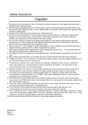
... Host system at Power off the drive Above sequence is performed by the following commands. - Note: The head is unload by the sequence #1 command, and the command completion normally takes about 400 ms. Considering the error retries, BIOS timer should be performed by the software control after power off . [Sequence #1]: Execute one of following BIOS sequence is automatically performed by control software, during Idle mode. Sleep Also, the normal...
... Host system at Power off the drive Above sequence is performed by the following commands. - Note: The head is unload by the sequence #1 command, and the command completion normally takes about 400 ms. Considering the error retries, BIOS timer should be performed by the software control after power off . [Sequence #1]: Execute one of following BIOS sequence is automatically performed by control software, during Idle mode. Sleep Also, the normal...

Owners Manual
Page 35
...V V V Write Commands Write Buffer PO 2 E8h D Write Sectors PO 2 30h, 31h V V V V Write Long PO 2 32h, 33h V V V V Write Multiple PO 3 C5h V V V V Write DMA DM 3 CAh,CBh V V V V Format Track PO 2 50h V VV Flush Cache ND 1 E7h D Seek Commands Recalibrate ND 1 1Xh D Seek ND 1 7Xh V V V Mode Set/Check, Diagnostic Execute Device Diagnostic ND 1 90h D Initialize Device Parameters ND 1 91h V V Identify Device PI 1 ECh D Set Features ND 1 EFh V D Set Multiple Mode ND 1 C6h V D Power Control Check Power Mode ND...
...V V V Write Commands Write Buffer PO 2 E8h D Write Sectors PO 2 30h, 31h V V V V Write Long PO 2 32h, 33h V V V V Write Multiple PO 3 C5h V V V V Write DMA DM 3 CAh,CBh V V V V Format Track PO 2 50h V VV Flush Cache ND 1 E7h D Seek Commands Recalibrate ND 1 1Xh D Seek ND 1 7Xh V V V Mode Set/Check, Diagnostic Execute Device Diagnostic ND 1 90h D Initialize Device Parameters ND 1 91h V V Identify Device PI 1 ECh D Set Features ND 1 EFh V D Set Multiple Mode ND 1 C6h V D Power Control Check Power Mode ND...

Owners Manual
Page 40
... NOP command supported Bit 13 1 = READ BUFFER command supported Bit 12 1 = WRITE BUFFER command supported Bit 11 0 = Reserved Bit 10 1 = Host Protected Area feature set supported Bit 9 1 = DEVICE RESET command supported Bit 8 1 = SERVICE interrupt supported Bit 7 1 = Release interrupt supported Bit 6 1 = Look-ahead supported Bit 5 1 = Write cache supported Bit 4 1 = Supports PACKET command feature set Bit 3 1 = Supports power management feature set Bit 2 1 = Supports removable feature set Bit 1 1 = Supports security feature set Bit 0 1 = Supports SMART feature set 83 Command set...
... NOP command supported Bit 13 1 = READ BUFFER command supported Bit 12 1 = WRITE BUFFER command supported Bit 11 0 = Reserved Bit 10 1 = Host Protected Area feature set supported Bit 9 1 = DEVICE RESET command supported Bit 8 1 = SERVICE interrupt supported Bit 7 1 = Release interrupt supported Bit 6 1 = Look-ahead supported Bit 5 1 = Write cache supported Bit 4 1 = Supports PACKET command feature set Bit 3 1 = Supports power management feature set Bit 2 1 = Supports removable feature set Bit 1 1 = Supports security feature set Bit 0 1 = Supports SMART feature set 83 Command set...

Owners Manual
Page 41
..., the SMART feature set to one, the Security Mode feature has been enabled via SECURITY SET PASSWORD command. Bit 4 1 = Supports PACKET command feature set Bit 3 1 = Supports power management feature set Bit 2 1 = Supports removable feature set Bit 1 1 = Supports Security Mode feature enabled If word 85 bit 1 is set has been enabled via SMART ENABLE OPERATIONS command. Bit 5 1 = Write cache enabled If word 85 bit 5 is set to one, read look-ahead has been enabled via SET FEATURE command. Word Table 6.5 Identify Device Information (Continued) Description 84 Command set/feature...
..., the SMART feature set to one, the Security Mode feature has been enabled via SECURITY SET PASSWORD command. Bit 4 1 = Supports PACKET command feature set Bit 3 1 = Supports power management feature set Bit 2 1 = Supports removable feature set Bit 1 1 = Supports Security Mode feature enabled If word 85 bit 1 is set has been enabled via SMART ENABLE OPERATIONS command. Bit 5 1 = Write cache enabled If word 85 bit 5 is set to one, read look-ahead has been enabled via SET FEATURE command. Word Table 6.5 Identify Device Information (Continued) Description 84 Command set/feature...

Owners Manual
Page 44
Bit 7 - 0 Signature Code "A5h" Value (HEX.) 0000h 0XXXh 0000h XXA5h Model DK23DA-40F DK23DA-30F DK23DA-20F DK23DA-10F Table 6.6 Identify Device information (Addressing) Word 1 Word 2 Word 3 Number of user addressable sectors in word 255. Maximum capacity in CHS mode is the two's complement of the sum of all bytes in word 0 through 254 and the byte consisting of bit 7:0 in LBA mode. *2. K6602705 Rev.3 08.20...
Bit 7 - 0 Signature Code "A5h" Value (HEX.) 0000h 0XXXh 0000h XXA5h Model DK23DA-40F DK23DA-30F DK23DA-20F DK23DA-10F Table 6.6 Identify Device information (Addressing) Word 1 Word 2 Word 3 Number of user addressable sectors in word 255. Maximum capacity in CHS mode is the two's complement of the sum of all bytes in word 0 through 254 and the byte consisting of bit 7:0 in LBA mode. *2. K6602705 Rev.3 08.20...

Owners Manual
Page 45
... number of corrupted data, if any. The Command Block Registers contain the cylinder, head, and sector numbers where the error occurred. 6.3.2.3.4 Read Long [22h, 23h] The Read Long command performs similarly to the Read Sectors command except that contained the error. When the Read Multiple command is still set and the data transfer should be transferred. 6.3.2.3.5 Read Multiple [C4h] This command is set prior to be 4 Bytes (Default). Subsequent blocks or partial blocks are supported. Only single sector read...
... number of corrupted data, if any. The Command Block Registers contain the cylinder, head, and sector numbers where the error occurred. 6.3.2.3.4 Read Long [22h, 23h] The Read Long command performs similarly to the Read Sectors command except that contained the error. When the Read Multiple command is still set and the data transfer should be transferred. 6.3.2.3.5 Read Multiple [C4h] This command is set prior to be 4 Bytes (Default). Subsequent blocks or partial blocks are supported. Only single sector read...

Owners Manual
Page 46
... transfer. 7) After detecting INTRQ, the host reads the Status Register. 8) The device clears the interrupt. 9) If another sector(block) is similar to the Write Sectors command, except that it writes the data and the ECC bytes directly from the host to the device. 1) The host writes any required parameters to the Features, Sector Count, Sector Number, Cylinder Low, Cylinder High, and Device/Head Registers. 2) The host writes the command code to the Command...
... transfer. 7) After detecting INTRQ, the host reads the Status Register. 8) The device clears the interrupt. 9) If another sector(block) is similar to the Write Sectors command, except that it writes the data and the ECC bytes directly from the host to the device. 1) The host writes any required parameters to the Features, Sector Count, Sector Number, Cylinder Low, Cylinder High, and Device/Head Registers. 2) The host writes the command code to the Command...

Owners Manual
Page 47
... the sector in error, regardless of the position in the Physical mode, but the Physical mode is specified in the event of an error. When the Write Multiple command is not in the Physical mode, the device executes a vendor specific operation. 6.3.2.5 Non-Data Commands Execution of these commands does not involve any data transfer. 1) The host writes any required parameters to the registers. 2) The host writes the command code to the Command...
... the sector in error, regardless of the position in the Physical mode, but the Physical mode is specified in the event of an error. When the Write Multiple command is not in the Physical mode, the device executes a vendor specific operation. 6.3.2.5 Non-Data Commands Execution of these commands does not involve any data transfer. 1) The host writes any required parameters to the registers. 2) The host writes the command code to the Command...

Owners Manual
Page 48
... Description Set transfer mode based on value in Sector Count register *2 Enable Advanced Power management *3 Enable Address Offset Mode *4 Disable retries Enable Vendor Unique ECC Byte Length(24 bytes) transfer Disable read look-ahead feature Disable reverting to power on defaults Disable ECC Disable Advanced Power management *3 Enable ECC Disable Address Offset Mode *4 Enable retries Enable read look-ahead feature Enable 4 bytes ECC transfer Enable reverting to power on defaults Enable write cache Disable write cache Default Ö Ö *1: If the code is posted. 6.3.2.5.4 Seek [7Xh...
... Description Set transfer mode based on value in Sector Count register *2 Enable Advanced Power management *3 Enable Address Offset Mode *4 Disable retries Enable Vendor Unique ECC Byte Length(24 bytes) transfer Disable read look-ahead feature Disable reverting to power on defaults Disable ECC Disable Advanced Power management *3 Enable ECC Disable Address Offset Mode *4 Enable retries Enable read look-ahead feature Enable 4 bytes ECC transfer Enable reverting to power on defaults Enable write cache Disable write cache Default Ö Ö *1: If the code is posted. 6.3.2.5.4 Seek [7Xh...

Owners Manual
Page 49
... the default mode at power on or after a hardware reset. 6.3.2.5.7 Execute device diagnostic [90h] This command allows the device to perform Read Multiple and Write Multiple operations. Table 6.9 Diagnostic Codes Code Contents 01 No Error 02 Controller error 03 Sector buffer error 05 CPU error 8X DRV1 error K6602705 Rev.3 08.20.01 - 49 - Table 6.8 Transfer mode code definition SC Transfer Mode 2Xh Multi-Word DMA Mode (X: 0, 1, 2): Mode 0: 4.1 MB/sec Mode 1: 13.3 MB/sec Mode 2: 16.6 MB/sec 4Xh Ultra DMA Mode (X: 0, 1, 2, 3, 4, 5): Mode...
... the default mode at power on or after a hardware reset. 6.3.2.5.7 Execute device diagnostic [90h] This command allows the device to perform Read Multiple and Write Multiple operations. Table 6.9 Diagnostic Codes Code Contents 01 No Error 02 Controller error 03 Sector buffer error 05 CPU error 8X DRV1 error K6602705 Rev.3 08.20.01 - 49 - Table 6.8 Transfer mode code definition SC Transfer Mode 2Xh Multi-Word DMA Mode (X: 0, 1, 2): Mode 0: 4.1 MB/sec Mode 1: 13.3 MB/sec Mode 2: 16.6 MB/sec 4Xh Ultra DMA Mode (X: 0, 1, 2, 3, 4, 5): Mode...
Owners Manual
Page 57
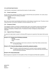
... diagnostic information on device that device reported are gathered at all error log data will be reset to the existing SMART Read Logging Sectors. 6.3.2.8.2 SMART Device Error Log Reporting The intent of an IDLE IMMEDIATE, STANDBY IMMEDIATE, or SLEEP command. X - If SMART is to augment the SMART feature set , a SMART enabled device automatically saves its attribute values upon receipt of SMART Device Error Log Reporting feature is disabled by client software "Download Utility". 6.3.2.8.3 SMART Operation with Power Management Modes When used in reduced power modes...
... diagnostic information on device that device reported are gathered at all error log data will be reset to the existing SMART Read Logging Sectors. 6.3.2.8.2 SMART Device Error Log Reporting The intent of an IDLE IMMEDIATE, STANDBY IMMEDIATE, or SLEEP command. X - If SMART is to augment the SMART feature set , a SMART enabled device automatically saves its attribute values upon receipt of SMART Device Error Log Reporting feature is disabled by client software "Download Utility". 6.3.2.8.3 SMART Operation with Power Management Modes When used in reduced power modes...

Owners Manual
Page 74
... of this command. Master password revision code set master password shall then unlock the device. The device shall then be saved as the new user password. The lock function shall be saved as the new user password. Identifier User User Master Security Level High Maximum High or Maximum Command Result The password supplied with the command shall be unlocked by only the user password. 6.3.2.9.5 Security Set Password [F1h] This command requests a transfer of a single sector of data from the next power-on or hardware reset. The following...
... of this command. Master password revision code set master password shall then unlock the device. The device shall then be saved as the new user password. The lock function shall be saved as the new user password. Identifier User User Master Security Level High Maximum High or Maximum Command Result The password supplied with the command shall be unlocked by only the user password. 6.3.2.9.5 Security Set Password [F1h] This command requests a transfer of a single sector of data from the next power-on or hardware reset. The following...

Owners Manual
Page 76
... data from the host. DK23DA-40F - DK23DA-20F - If the device receives a Security Erase Unit command without an immediately prior Security Erase Prepare command, the device aborts the Security Erase unit command This command disables the device lock function, however, the master password is still stored internally within the device and may be issued immediately before the Security Erase Unit command to enable device erasing and unlocking. DK23DA-30F - 6.3.2.9.7 Security Erase Prepare [F3h] The Security Erase Prepare command shall be reactivated later when a new user password...
... data from the host. DK23DA-40F - DK23DA-20F - If the device receives a Security Erase Unit command without an immediately prior Security Erase Prepare command, the device aborts the Security Erase unit command This command disables the device lock function, however, the master password is still stored internally within the device and may be issued immediately before the Security Erase Unit command to enable device erasing and unlocking. DK23DA-30F - 6.3.2.9.7 Security Erase Prepare [F3h] The Security Erase Prepare command shall be reactivated later when a new user password...

Owners Manual
Page 78
... Security Erase Unit Executable Executable Security Freeze Lock Aborted Executable Security Set Password Aborted Executable Security Unlock Executable Executable Seek Executable Executable Set Features Executable Executable Set Multiple Mode Executable Executable Sleep Executable Executable SMART Automatic Enable/Disable Executable Executable Off-line SMART Execute Off-line Immediate Executable Executable SMART Disable Operations Executable Executable SMART Enable/Disable AUTOSAVE Executable Executable SMART Enable Operations Executable Executable SMART...
... Security Erase Unit Executable Executable Security Freeze Lock Aborted Executable Security Set Password Aborted Executable Security Unlock Executable Executable Seek Executable Executable Set Features Executable Executable Set Multiple Mode Executable Executable Sleep Executable Executable SMART Automatic Enable/Disable Executable Executable Off-line SMART Execute Off-line Immediate Executable Executable SMART Disable Operations Executable Executable SMART Enable/Disable AUTOSAVE Executable Executable SMART Enable Operations Executable Executable SMART...

Owners Manual
Page 80
... be removed by the Identify Device command back to exist in the Identify Device data is in the Set Max Frozen mode. 6.3.2.10.2 Address Offset Feature Computer systems perform initial code booting by Set Feature Command Subcommand 89h "Disable Address Offset Mode", Software Reset, Hardware Reset or Power on Reset. A subsequent Set Max Address Command using the Set Max Address Command. The Set Max Unlock command changes the device from a predefined address on a disk drive. When this command is accepted the device is the size of the drive returned...
... be removed by the Identify Device command back to exist in the Identify Device data is in the Set Max Frozen mode. 6.3.2.10.2 Address Offset Feature Computer systems perform initial code booting by Set Feature Command Subcommand 89h "Disable Address Offset Mode", Software Reset, Hardware Reset or Power on Reset. A subsequent Set Max Address Command using the Set Max Address Command. The Set Max Unlock command changes the device from a predefined address on a disk drive. When this command is accepted the device is the size of the drive returned...

Owners Manual
Page 87
...over power-down and powered-up , the DEVICE CONFIGURATION RESTORE command returns command aborted. A DEVICE CONFIGURATION IDENTIFY command indicates the selectable commands, modes, capacity, and feature sets that the device is supported and enabled can be cleared by a DEVICE CONFIGURATION SET command. A DEVICE CONFIGURATION RESTORE command disables an overlay that a command, mode, capacity, or feature set is capable of DEVICE CONFIGURATION SET command this information is powered-down and power-up. A device always powers-up , the DEVICE CONFIGURATION RESTORE SET command returns command...
...over power-down and powered-up , the DEVICE CONFIGURATION RESTORE command returns command aborted. A DEVICE CONFIGURATION IDENTIFY command indicates the selectable commands, modes, capacity, and feature sets that the device is supported and enabled can be cleared by a DEVICE CONFIGURATION SET command. A DEVICE CONFIGURATION RESTORE command disables an overlay that a command, mode, capacity, or feature set is capable of DEVICE CONFIGURATION SET command this information is powered-down and power-up. A device always powers-up , the DEVICE CONFIGURATION RESTORE SET command returns command...

Owners Manual
Page 88
... by a SET MAX ADDRESS command, the device returns command aborted. 6.3.2.11.2 Device Configuration Freeze Lock [B1h, Sub 01h] Task File Registers Command Cylinder High Cylinder Low Device/Head Sector Number Sector Count Features DRV : Device selection bit 76543210 B1h XX XX - 6.3.2.11.1 Device Configuration Restore [B1h, Sub 00h] Task File Registers Command Cylinder High Cylinder Low Device/Head Sector Number Sector Count Features DRV : Device selection bit 76543210 B1h XX XX - If DEVICE CONFIGURATION FREEZE LOCK is not cleared by hardware or software reset. DRV XX...
... by a SET MAX ADDRESS command, the device returns command aborted. 6.3.2.11.2 Device Configuration Freeze Lock [B1h, Sub 01h] Task File Registers Command Cylinder High Cylinder Low Device/Head Sector Number Sector Count Features DRV : Device selection bit 76543210 B1h XX XX - 6.3.2.11.1 Device Configuration Restore [B1h, Sub 00h] Task File Registers Command Cylinder High Cylinder Low Device/Head Sector Number Sector Count Features DRV : Device selection bit 76543210 B1h XX XX - If DEVICE CONFIGURATION FREEZE LOCK is not cleared by hardware or software reset. DRV XX...


