
Owners Manual
Page 9
Capacity Model (Formatted) Height Interface DK23DA-40F DK23DA-30F DK23DA-20F DK23DA-10F 40.007 GB 30.005 GB 20.003 GB 10.056 GB 9.5 mm 9.5 mm 9.5 mm 9.5 mm ATA-5(IDE) ATA-5(IDE) ATA-5(IDE) ATA-5(IDE) [Features] - Auto Read Reassign/Auto ... DMA mode-5 (Device-Buffer) - 18.7 to 34.7 MB/sec - Read-ahead Cache/Write Cache - FDB(Fruid Brting) Motor - Load/Unload Mechanism - 95 grams(DK23DA-40F/30F)/91 grams(DK23DA-20F/10F) - Rotary Actuator - MCC 2.5 inch Small Form Factor(9.5mm height) [Identify Device Information for 9.5mm height) in CHS mode is 8,455MB. Word 60...
Capacity Model (Formatted) Height Interface DK23DA-40F DK23DA-30F DK23DA-20F DK23DA-10F 40.007 GB 30.005 GB 20.003 GB 10.056 GB 9.5 mm 9.5 mm 9.5 mm 9.5 mm ATA-5(IDE) ATA-5(IDE) ATA-5(IDE) ATA-5(IDE) [Features] - Auto Read Reassign/Auto ... DMA mode-5 (Device-Buffer) - 18.7 to 34.7 MB/sec - Read-ahead Cache/Write Cache - FDB(Fruid Brting) Motor - Load/Unload Mechanism - 95 grams(DK23DA-40F/30F)/91 grams(DK23DA-20F/10F) - Rotary Actuator - MCC 2.5 inch Small Form Factor(9.5mm height) [Identify Device Information for 9.5mm height) in CHS mode is 8,455MB. Word 60...

Owners Manual
Page 13
...DK23DA- DK23DA- 40F 30F 20F 10F 1 Capacity per drive (Formatted) Capacity per sector Disks Heads Cylinders 2 Seek time Average (Nominal Maximum value) Minimum 3 Average latency Disk rotational speed 4 Recording density Track density Recording method 5 Interface Data transfer rate (Disk-Buffer) Data transfer rate (Host-Buffer) 40.007 30...33 A(1.65W) -Seek *8 0.45 A(2.25W) - Ready *2 Sleep/Standby - DK23DA- Start up *5 0.90 A(4.5W) - Standby 0.050 A(0.25W) - 3.0 Specification Summary 3.1 Principal Specifications Table 3.1 Principal Specifications ...
...DK23DA- DK23DA- 40F 30F 20F 10F 1 Capacity per drive (Formatted) Capacity per sector Disks Heads Cylinders 2 Seek time Average (Nominal Maximum value) Minimum 3 Average latency Disk rotational speed 4 Recording density Track density Recording method 5 Interface Data transfer rate (Disk-Buffer) Data transfer rate (Host-Buffer) 40.007 30...33 A(1.65W) -Seek *8 0.45 A(2.25W) - Ready *2 Sleep/Standby - DK23DA- Start up *5 0.90 A(4.5W) - Standby 0.050 A(0.25W) - 3.0 Specification Summary 3.1 Principal Specifications Table 3.1 Principal Specifications ...
Owners Manual
Page 17
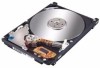
... number of emergency unload is defined separately. 3.4.3 Required Power Off Sequence To operate the load/unload normally, the following BIOS sequence is limited to over 30 sec by the Host side. [Sequence #3]: Power off the drive Above sequence is required for the Host system at Power off, Suspend and Hibernation operations...
... number of emergency unload is defined separately. 3.4.3 Required Power Off Sequence To operate the load/unload normally, the following BIOS sequence is limited to over 30 sec by the Host side. [Sequence #3]: Power off the drive Above sequence is required for the Host system at Power off, Suspend and Hibernation operations...
Owners Manual
Page 27
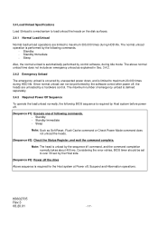
...) 2 GND 4 DD8 6 DD9 8 DD10 10 DD11 12 DD12 14 DD13 16 DD14 18 DD15 20 KEY(Removed) 22 GND 24 GND 26 GND 28 CSEL 30 GND 32 IOCS16- 34 PDIAG- 36 DA2 38 CS1- 40 GND(Motor) 42 5VDC(Motor) 44 Reserved PCB K6602705 Rev.3 08.20.01 - 27 -
...) 2 GND 4 DD8 6 DD9 8 DD10 10 DD11 12 DD12 14 DD13 16 DD14 18 DD15 20 KEY(Removed) 22 GND 24 GND 26 GND 28 CSEL 30 GND 32 IOCS16- 34 PDIAG- 36 DA2 38 CS1- 40 GND(Motor) 42 5VDC(Motor) 44 Reserved PCB K6602705 Rev.3 08.20.01 - 27 -
Owners Manual
Page 30
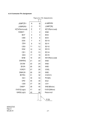
... present when the power is received from the host, the device asserts this signal. The host in the host system. K6602705 Rev.3 08.20.01 - 30 - The device shall assert this signal, used for the detail. The I/O signal levels are as follows. (1) Input signal High level +2.0V to Vcc+0.5V Low...
... present when the power is received from the host, the device asserts this signal. The host in the host system. K6602705 Rev.3 08.20.01 - 30 - The device shall assert this signal, used for the detail. The I/O signal levels are as follows. (1) Input signal High level +2.0V to Vcc+0.5V Low...

Owners Manual
Page 38
... = DMA supported Bit 7 - 0 Vendor Specific Value (HEX.) 045Ah See table 6.6 C837h See table 6.6 0000h See table 6.6 0003h DK23DA-20F/ 10F: 0400h DK23DA-40F/ 30F: 1000h 0004h 8010h 0000h 0B00h K6602705 Rev.3 08.20.01 - 38 - The host then reads the information from the device... READ/WRITE LONG commands 23-26 Firmware revision(8 ASCII Characters) 27-46 Model number(40 ASCII Characters) DK23DA-40F: "HITACHI_DK23DA-40" DK23DA-30F: "HITACHI_DK23DA-30" DK23DA-20F: "HITACHI_DK23DA-20" DK23DA-10F: "HITACHI_DK23DA-10" 47 Number of sectors on multiple commands Bit 15 - 8 80h (fixed) ...
... = DMA supported Bit 7 - 0 Vendor Specific Value (HEX.) 045Ah See table 6.6 C837h See table 6.6 0000h See table 6.6 0003h DK23DA-20F/ 10F: 0400h DK23DA-40F/ 30F: 1000h 0004h 8010h 0000h 0B00h K6602705 Rev.3 08.20.01 - 38 - The host then reads the information from the device... READ/WRITE LONG commands 23-26 Firmware revision(8 ASCII Characters) 27-46 Model number(40 ASCII Characters) DK23DA-40F: "HITACHI_DK23DA-40" DK23DA-30F: "HITACHI_DK23DA-30" DK23DA-20F: "HITACHI_DK23DA-20" DK23DA-10F: "HITACHI_DK23DA-10" 47 Number of sectors on multiple commands Bit 15 - 8 80h (fixed) ...
Owners Manual
Page 50
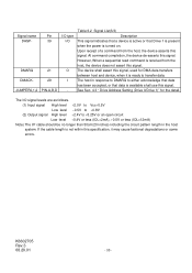
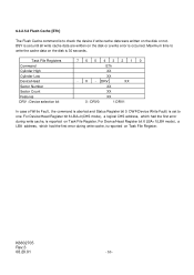
... written on the disk or a write error is reported on Task File Register. BSY is set to write the cache data on the disk is 30 seconds. For Device/Head Register bit 6 LBA=0(CHS mode), a logical CHS address, which had the first error during write cache, is to check the device...
... written on the disk or a write error is reported on Task File Register. BSY is set to write the cache data on the disk is 30 seconds. For Device/Head Register bit 6 LBA=0(CHS mode), a logical CHS address, which had the first error during write cache, is to check the device...

Owners Manual
Page 52
... Management sub-command disables the APM operation. The device automatically moves to 01h, the power consumption is getting worse. The timer can be set to 30 minutes. 6.3.2.6.2 Advanced Power Management The host can be set the mode and reset the mode. - The device has five levels of APM operation mode(APM...
... Management sub-command disables the APM operation. The device automatically moves to 01h, the power consumption is getting worse. The timer can be set to 30 minutes. 6.3.2.6.2 Advanced Power Management The host can be set the mode and reset the mode. - The device has five levels of APM operation mode(APM...
Owners Manual
Page 54
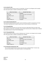
Sector Count Value SC = 0 0 The Sector Count Register sets the standby timer value. 6.3.2.6.4 Idle [97h, E3h] This command causes the device to enter to the Idle Mode. By the power on default, the Standby timer is disabled.
Sector Count Value SC = 0 0 The Sector Count Register sets the standby timer value. 6.3.2.6.4 Idle [97h, E3h] This command causes the device to enter to the Idle Mode. By the power on default, the Standby timer is disabled.
Owners Manual
Page 96
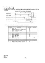
... DD0-15(16 bit) or DD0-7(8 bit) SYMBOL Description MIN(ns) t0 Cycle Time 120 t1 Address Valid to Address Valid Hold 10 MAX(ns) 30 40 30 K6602705 Rev.3 08.20.01 - 96 - Data Setup 20 t6 DIOR- Negation (MAX) t9 DIOR-/DIOW- Data Setup 20 t4 DIOW- Data tristate t7...
... DD0-15(16 bit) or DD0-7(8 bit) SYMBOL Description MIN(ns) t0 Cycle Time 120 t1 Address Valid to Address Valid Hold 10 MAX(ns) 30 40 30 K6602705 Rev.3 08.20.01 - 96 - Data Setup 20 t6 DIOR- Negation (MAX) t9 DIOR-/DIOW- Data Setup 20 t4 DIOW- Data tristate t7...
Owners Manual
Page 109
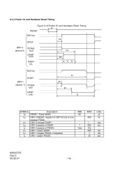
... DASP-- tN1 DRV 1 negate PDIAG- tR0 DRV 0 sample of DASP- 1 tS DRV 0 sample of PDIAG- 1ms tR1 DRV 1 assert DASP- MAX 400 1 450 31s 400 1 30 Units ms ns ms ms ms ms sec K6602705 Rev.3 08.20.01 - 109 -
... DASP-- tN1 DRV 1 negate PDIAG- tR0 DRV 0 sample of DASP- 1 tS DRV 0 sample of PDIAG- 1ms tR1 DRV 1 assert DASP- MAX 400 1 450 31s 400 1 30 Units ms ns ms ms ms ms sec K6602705 Rev.3 08.20.01 - 109 -