Owners Manual
Page 1
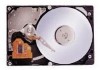
Keep this manual with care. K6610007 Rev.5 02.14.'03 H I T A C H I All Rights Reserved, Copyright ©2002-2003 Hitachi, Ltd. (Total 113 pages) - 1 - Read and recommend drive usage cautions to your end user. OEM Manual DK23FB-60/40/20 Disk Drive Specifications REV.5 Caution for Safety Read Safety descriptions carefully.
Keep this manual with care. K6610007 Rev.5 02.14.'03 H I T A C H I All Rights Reserved, Copyright ©2002-2003 Hitachi, Ltd. (Total 113 pages) - 1 - Read and recommend drive usage cautions to your end user. OEM Manual DK23FB-60/40/20 Disk Drive Specifications REV.5 Caution for Safety Read Safety descriptions carefully.

Owners Manual
Page 7
... D9h] 58 6.3.2.8.7 SMART Return Status [B0h, Sub DAh] 59 6.3.2.8.8 SMART Enable/Disable Attribute AUTOSAVE [B0h, Sub D2h 59 6.3.2.8.9 SMART Save Attribute Values [B0h, Sub D3h] 60 6.3.2.8.10 SMART Enable/Disable Automatic Off-line [B0h, Sub DBh 61 6.3.2.8.11 SMART Execute Off-line Immediate [B0h, Sub D4h 62 K6610007 Rev.5 02.14...
... D9h] 58 6.3.2.8.7 SMART Return Status [B0h, Sub DAh] 59 6.3.2.8.8 SMART Enable/Disable Attribute AUTOSAVE [B0h, Sub D2h 59 6.3.2.8.9 SMART Save Attribute Values [B0h, Sub D3h] 60 6.3.2.8.10 SMART Enable/Disable Automatic Off-line [B0h, Sub DBh 61 6.3.2.8.11 SMART Execute Off-line Immediate [B0h, Sub D4h 62 K6610007 Rev.5 02.14...
Owners Manual
Page 9
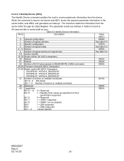
... DK23FB series disk drives reach high capacities (60/40/20GB for Setup] Table 1.1 Identify Device information (Addressing) Model Word 1 Word 3 Word 6 Number of SPT DK23FB-60 16383 (*1) 16 63 (3FFFh) (0010h) (3Fh) DK23FB-40 16383 (*1) 16 63 (3FFFh) (0010h) (3Fh) DK23FB-20 16383 (*1) 16 ... Maximum capacity in a 2.5 type form factor by applying the latest high-density recording technology. Model DK23FB-60 DK23FB-40 DK23FB-20 Capacity (Formatted) 60.011 GB 40.007 GB 20.003 GB Height 9.5 mm 9.5 mm 9.5 mm Interface ATA-5(IDE) ATA-5(IDE) ATA-5(IDE) [Features] - ...
... DK23FB series disk drives reach high capacities (60/40/20GB for Setup] Table 1.1 Identify Device information (Addressing) Model Word 1 Word 3 Word 6 Number of SPT DK23FB-60 16383 (*1) 16 63 (3FFFh) (0010h) (3Fh) DK23FB-40 16383 (*1) 16 63 (3FFFh) (0010h) (3Fh) DK23FB-20 16383 (*1) 16 ... Maximum capacity in a 2.5 type form factor by applying the latest high-density recording technology. Model DK23FB-60 DK23FB-40 DK23FB-20 Capacity (Formatted) 60.011 GB 40.007 GB 20.003 GB Height 9.5 mm 9.5 mm 9.5 mm Interface ATA-5(IDE) ATA-5(IDE) ATA-5(IDE) [Features] - ...
Owners Manual
Page 12
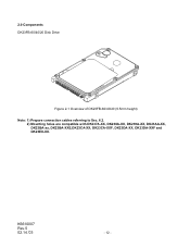
2.0 Components DK23FB-60/40/20 Disk Drive Figure 2-1 Overview of DK23FB-60/40/20 (9.5mm height) Note: 1) Prepare connection cables referring to Sec. 6.2. 2) Mounting holes are compatible with DK237A-XX, DK238A-XX, DK239A-XX, DK23AA-XX, DK23BA-xx, DK23BA-XXE,DK23CA-XX, DK23CA-XXF, DK23DA-XX, DK23DA-XXF and DK23EX-XX. K6610007 Rev.5 02.14.'03 - 12 -
2.0 Components DK23FB-60/40/20 Disk Drive Figure 2-1 Overview of DK23FB-60/40/20 (9.5mm height) Note: 1) Prepare connection cables referring to Sec. 6.2. 2) Mounting holes are compatible with DK237A-XX, DK238A-XX, DK239A-XX, DK23AA-XX, DK23BA-xx, DK23BA-XXE,DK23CA-XX, DK23CA-XXF, DK23DA-XX, DK23DA-XXF and DK23EX-XX. K6610007 Rev.5 02.14.'03 - 12 -

Owners Manual
Page 13
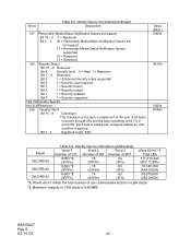
... Table 3.1 Principal Specifications Specifications No. Idle *6 91 100mvp-p or less 0.9 A(4.5W) 0.17 A(0.85W) grams - Standby 0.03 A(0.15W) - Item DK23FB-60 DK23FB-40 DK23FB-20 Units 1 Capacity per drive (Formatted) 60.011 40.007 20.003 GB Capacity per sector 512 Bytes Disks 2 1 Heads 4 3 2 Cylinders 42518 2 Seek time Average 13 *1 ms (Nominal Maximum 24 *1 ms value) Minimum...
... Table 3.1 Principal Specifications Specifications No. Idle *6 91 100mvp-p or less 0.9 A(4.5W) 0.17 A(0.85W) grams - Standby 0.03 A(0.15W) - Item DK23FB-60 DK23FB-40 DK23FB-20 Units 1 Capacity per drive (Formatted) 60.011 40.007 20.003 GB Capacity per sector 512 Bytes Disks 2 1 Heads 4 3 2 Cylinders 42518 2 Seek time Average 13 *1 ms (Nominal Maximum 24 *1 ms value) Minimum...
Owners Manual
Page 15
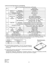
... Reliability No. Please see specification 5.1 Packing for reference. Item Specification DK23FB-60/40/20 1 Ambient *1 Operational 5 to 55°C temperature Non-operational -40 to 70°C *2 Temperature gradient Max. 20°C /hour 2 Relative humidity Operational 5 to 90 % Non-operational 5 to 0°C, the drive should be packed in HDD package box. Please see specification 5.1 Packing...
... Reliability No. Please see specification 5.1 Packing for reference. Item Specification DK23FB-60/40/20 1 Ambient *1 Operational 5 to 55°C temperature Non-operational -40 to 70°C *2 Temperature gradient Max. 20°C /hour 2 Relative humidity Operational 5 to 90 % Non-operational 5 to 0°C, the drive should be packed in HDD package box. Please see specification 5.1 Packing...
Owners Manual
Page 16
... conditions. K6610007 Rev.5 02.14.'03 - 16 - Seek rate = 0.4/(average access time + average latency) = 0.4/(average access time + 60/RPM/2) *5 : Caution Data reliability is specified at each axis. The heads are to system ground with ISO 7779. The spindle motor is designed... resistor. -External Magnetic Field : Within specifications given in Table 3.1 "Principal Specifications" -Drive Grounding : Drive frame should be used to be less than 50 mAp-p (Frequency Range: less than 20% of the drive. *4 : 3.9 Bels are defined for each cylinder. This value is not to compromise...
... conditions. K6610007 Rev.5 02.14.'03 - 16 - Seek rate = 0.4/(average access time + average latency) = 0.4/(average access time + 60/RPM/2) *5 : Caution Data reliability is specified at each axis. The heads are to system ground with ISO 7779. The spindle motor is designed... resistor. -External Magnetic Field : Within specifications given in Table 3.1 "Principal Specifications" -Drive Grounding : Drive frame should be used to be less than 50 mAp-p (Frequency Range: less than 20% of the drive. *4 : 3.9 Bels are defined for each cylinder. This value is not to compromise...
Owners Manual
Page 18
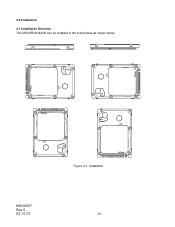
K6610007 Rev.5 02.14.'03 Figure 4-1 Installation - 18 - 4.0 Installation 4.1 Installation Direction The DK23FB-60/40/20 can be installed in the 6 directions as shown below.
K6610007 Rev.5 02.14.'03 Figure 4-1 Installation - 18 - 4.0 Installation 4.1 Installation Direction The DK23FB-60/40/20 can be installed in the 6 directions as shown below.
Owners Manual
Page 22
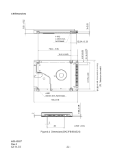
full thread 100±0.45 3.99±0.25 K6610007 Rev.5 02.14.'03 2 42 (Unit : mm) Figure 4-4 Dimensions (DK23FB-60/40/20) - 22 - 3±0.25 4.07±0.25 10.14±0.375 69.85±0.25 Drive width at mounting (70.1 Maximum drive width) 9.5 ± 0.2 2 4.4 Dimensions 4-M3 3.5mm min. full thread 76.6 ± 0.25 14.0 ± 0.25 10.24 ± 0.25 61.72±0.25 4-M3 3.0mm min.
full thread 100±0.45 3.99±0.25 K6610007 Rev.5 02.14.'03 2 42 (Unit : mm) Figure 4-4 Dimensions (DK23FB-60/40/20) - 22 - 3±0.25 4.07±0.25 10.14±0.375 69.85±0.25 Drive width at mounting (70.1 Maximum drive width) 9.5 ± 0.2 2 4.4 Dimensions 4-M3 3.5mm min. full thread 76.6 ± 0.25 14.0 ± 0.25 10.24 ± 0.25 61.72±0.25 4-M3 3.0mm min.
Owners Manual
Page 38
...3 Number of logical heads 4 - 5 Retired 6 Number of logical sectors per logical track 7-9 Vendor specific 10-19 Serial number (20 ASCII characters) 20 Retired 21 Retired 22 Number of ECC bytes passed on READ/WRITE LONG commands 23-26 Firmware revision(8 ASCII Characters) 27-46 Model ...number(40 ASCII Characters) DK23FB-60: "HITACHI_DK23FB-60" DK23FB-40: "HITACHI_DK23FB-40" DK23FB-20: "HITACHI_DK23FB-20" 47 Number of sectors on multiple commands Bit 15 - 8 80h (fixed) Bit 7 - 0 Number of ...
...3 Number of logical heads 4 - 5 Retired 6 Number of logical sectors per logical track 7-9 Vendor specific 10-19 Serial number (20 ASCII characters) 20 Retired 21 Retired 22 Number of ECC bytes passed on READ/WRITE LONG commands 23-26 Firmware revision(8 ASCII Characters) 27-46 Model ...number(40 ASCII Characters) DK23FB-60: "HITACHI_DK23FB-60" DK23FB-40: "HITACHI_DK23FB-40" DK23FB-20: "HITACHI_DK23FB-20" 47 Number of sectors on multiple commands Bit 15 - 8 80h (fixed) Bit 7 - 0 Number of ...

Owners Manual
Page 39
...) Bit 14 1 (fixed) Bit 13 - 1 0 = Reserved Bit 0 1 = Standby timer value is valid Bit 7 - 0Current setting for number of current sectors per interrupt on R/W MULTIPLE command 60-61 Total addressable LBA 62 Obsolete 63 Multi-word DMA transfer Bit 15 - 8 Multi-word DMA transfer mode active Bit 7 - 0Multi-word DMA transfer mode...
...) Bit 14 1 (fixed) Bit 13 - 1 0 = Reserved Bit 0 1 = Standby timer value is valid Bit 7 - 0Current setting for number of current sectors per interrupt on R/W MULTIPLE command 60-61 Total addressable LBA 62 Obsolete 63 Multi-word DMA transfer Bit 15 - 8 Multi-word DMA transfer mode active Bit 7 - 0Multi-word DMA transfer mode...
Owners Manual
Page 44
...16 63 (3FFFh) (0010h) (3Fh) 16383 *2 16 63 (3FFFh) (0010h) (3Fh) Word 60•61 *1 Total LBA 117,210,240 (6FC 7C80h) 78,140,160 (4A8 5300h) 39,070,080 (254 2980h) *1: Words 60-61 reflect the total number of CYL. The checksum is ignored. Bit 7 - 0 Signature Code "A5h..." Value (HEX.) 0000h 0XXXh 0000h XXA5h Model DK23FB-60 DK23FB-40 DK23FB-20 Table 6.6 Identify Device information (Addressing) Word 1 Word 2 Word 3 Number of user addressable sectors in LBA mode. *2. Each byte is added ...
...16 63 (3FFFh) (0010h) (3Fh) 16383 *2 16 63 (3FFFh) (0010h) (3Fh) Word 60•61 *1 Total LBA 117,210,240 (6FC 7C80h) 78,140,160 (4A8 5300h) 39,070,080 (254 2980h) *1: Words 60-61 reflect the total number of CYL. The checksum is ignored. Bit 7 - 0 Signature Code "A5h..." Value (HEX.) 0000h 0XXXh 0000h XXA5h Model DK23FB-60 DK23FB-40 DK23FB-20 Table 6.6 Identify Device information (Addressing) Word 1 Word 2 Word 3 Number of user addressable sectors in LBA mode. *2. Each byte is added ...

Owners Manual
Page 60
... if the values in the Features, Cylinder Low, or Cylinder High registers are invalid, an Aborted command error is posted. K6610007 Rev.5 02.14.'03 - 60 - A value of the attribute AUTOSAVE feature (either enable or disable) will be preserved by the device across power cycles. If the device receives a command from...
... if the values in the Features, Cylinder Low, or Cylinder High registers are invalid, an Aborted command error is posted. K6610007 Rev.5 02.14.'03 - 60 - A value of the attribute AUTOSAVE feature (either enable or disable) will be preserved by the device across power cycles. If the device receives a command from...

Owners Manual
Page 66
... error creates an error log data structure that replaces the first error log data structure; Byte n ~ n+11 n+12 ~ n+23 n+24 ~ n+35 n+36 ~ n+47 n+48 ~ n+59 n+60 ~ n+89 Table 6.14 Error log data structure Description First command data structure Second command data structure Third command data structure Fourth command data structure Fifth...
... error creates an error log data structure that replaces the first error log data structure; Byte n ~ n+11 n+12 ~ n+23 n+24 ~ n+35 n+36 ~ n+47 n+48 ~ n+59 n+60 ~ n+89 Table 6.14 Error log data structure Description First command data structure Second command data structure Third command data structure Fourth command data structure Fifth...
Owners Manual
Page 77
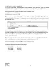
... of the device. The Security Erase Prepare command shall be issued immediately before the Security Erase Unit command to enable device erasing and unlocking. DK23FB-60 : - This command is in Frozen mode. 6.3.2.9.8 Security Erase Unit [F4h] This command requests a transfer of a single sector of information. Device ...may be reactivated later when a new user password is in Frozen mode. The execution time of this sector of data from the host. DK23FB-20 : 44 minutes 28 minutes 12 minutes K6610007 Rev.5 02.14.'03 - 77 - If the password does not match, then the device ...
... of the device. The Security Erase Prepare command shall be issued immediately before the Security Erase Unit command to enable device erasing and unlocking. DK23FB-60 : - This command is in Frozen mode. 6.3.2.9.8 Security Erase Unit [F4h] This command requests a transfer of a single sector of information. Device ...may be reactivated later when a new user password is in Frozen mode. The execution time of this sector of data from the host. DK23FB-20 : 44 minutes 28 minutes 12 minutes K6610007 Rev.5 02.14.'03 - 77 - If the password does not match, then the device ...
Owners Manual
Page 85
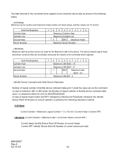
... x 63) for the Maximum LBA in LBA mode, the Number of logical cylinder of current cylinders is posted by host is not used for DK23FB-60/40/20. Task File Registers Cylinder High Cylinder Low Device/Head Sector Number 7 6 5 4 3 2 1 0 Maximum LBA Bit23 -16 Maximum LBA Bit15 - 8 - 1 - DRV Maximum LBA Bit27 - 24 Maximum...
... x 63) for the Maximum LBA in LBA mode, the Number of logical cylinder of current cylinders is posted by host is not used for DK23FB-60/40/20. Task File Registers Cylinder High Cylinder Low Device/Head Sector Number 7 6 5 4 3 2 1 0 Maximum LBA Bit23 -16 Maximum LBA Bit15 - 8 - 1 - DRV Maximum LBA Bit27 - 24 Maximum...

Owners Manual
Page 91
...-test supported bit 0 1 = SMART feature set supported bit 6 1 = Automatic acoustic management supported bit 5 1 = R/W DMA QUEUED commands supported bit 4 1 = Power-up in the factory default DK23FB-20: 254 297Fh condition. The sum of all byte in words 0 through 254 and the byte consisting of bits 7:0 of all bytes is zero when the... "A5h" K6610007 Rev.5 02.14.'03 - 91 - Word 3 - 6 7 8 - 254 255 Table 6.18 Device Configuration Identify Data Structure (continued) Description Value (HEX.) Maximum LBA Address DK23FB-60: 6FC 7C7Fh Words 4 - 7 define the maximum LBA address.
...-test supported bit 0 1 = SMART feature set supported bit 6 1 = Automatic acoustic management supported bit 5 1 = R/W DMA QUEUED commands supported bit 4 1 = Power-up in the factory default DK23FB-20: 254 297Fh condition. The sum of all byte in words 0 through 254 and the byte consisting of bits 7:0 of all bytes is zero when the... "A5h" K6610007 Rev.5 02.14.'03 - 91 - Word 3 - 6 7 8 - 254 255 Table 6.18 Device Configuration Identify Data Structure (continued) Description Value (HEX.) Maximum LBA Address DK23FB-60: 6FC 7C7Fh Words 4 - 7 define the maximum LBA address.

Owners Manual
Page 102
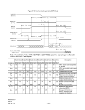
SYMBOL tRFS tRP Mode 0(ns) Mode 1(ns) Mode 2(ns) Mode3(ns) MIN MAX MIN MAX MIN MAX MIN MAX 75 70 60 60 160 125 100 100 Mode4(ns) MIN MAX 60 100 Mode5(ns) Description MIN MAX 50 Ready-to-final STROBE time 85 Ready-to request termination of the Ultra DMA burst no sooner than tRP after HDMARDYis negated. Figure 6-10 Host pausing an Ultra DMA Read DMARQ (device) DMACK(host) STOP tRP (host) HDMARDY(host) tRFS DSTROBE (device) DD(15:0) (device) Note: The host asserts STOP to -pause time K6610007 Rev.5 02.14.'03 - 102 -
SYMBOL tRFS tRP Mode 0(ns) Mode 1(ns) Mode 2(ns) Mode3(ns) MIN MAX MIN MAX MIN MAX MIN MAX 75 70 60 60 160 125 100 100 Mode4(ns) MIN MAX 60 100 Mode5(ns) Description MIN MAX 50 Ready-to-final STROBE time 85 Ready-to request termination of the Ultra DMA burst no sooner than tRP after HDMARDYis negated. Figure 6-10 Host pausing an Ultra DMA Read DMARQ (device) DMACK(host) STOP tRP (host) HDMARDY(host) tRFS DSTROBE (device) DD(15:0) (device) Note: The host asserts STOP to -pause time K6610007 Rev.5 02.14.'03 - 102 -
Owners Manual
Page 104
... 20 20 20 20 20 20 Maximum time before releasing IORDY tACK 20 20 20 20 20 20 Setup and hold times before assertion and negation of DMACK_ K6610007 Rev.5 02.14.'03 - 104 - Note: The definitions for output drivers turning on tRFS 75 70 60 60 60 50 Ready-to-final-STROBE time tRP 160 125 100 100 100 85 Ready-to release tZAH 20 20 20 20 20 20...
... 20 20 20 20 20 20 Maximum time before releasing IORDY tACK 20 20 20 20 20 20 Setup and hold times before assertion and negation of DMACK_ K6610007 Rev.5 02.14.'03 - 104 - Note: The definitions for output drivers turning on tRFS 75 70 60 60 60 50 Ready-to-final-STROBE time tRP 160 125 100 100 100 85 Ready-to release tZAH 20 20 20 20 20 20...

Owners Manual
Page 107
SYMBOL tRFS tRP Mode 0(ns) Mode 1(ns) Mode 2(ns) MIN MAX MIN MAX MIN MAX 75 70 60 160 125 100 Mode 3(ns) MIN MAX 60 100 Mode 4(ns) Mde5(ns) Description MIN MAX MIN MAX 60 50 Ready-to-final STROBE time 100 85 Ready-to request termination of the Ultra DMA burst no sooner than tRP after DDMARDY- DMARQ (device) DMACK- (host) STOP (host) Figure 6-15 Device pausing an Ultra DMA Write tRP DDMARDY(device) tRFS HSTROBE (host) DD(15:0) (host) Note: The device negates DMARQ to -pause time K6610007 Rev.5 02.14.'03 - 107 - is negated.
SYMBOL tRFS tRP Mode 0(ns) Mode 1(ns) Mode 2(ns) MIN MAX MIN MAX MIN MAX 75 70 60 160 125 100 Mode 3(ns) MIN MAX 60 100 Mode 4(ns) Mde5(ns) Description MIN MAX MIN MAX 60 50 Ready-to-final STROBE time 100 85 Ready-to request termination of the Ultra DMA burst no sooner than tRP after DDMARDY- DMARQ (device) DMACK- (host) STOP (host) Figure 6-15 Device pausing an Ultra DMA Write tRP DDMARDY(device) tRFS HSTROBE (host) DD(15:0) (host) Note: The device negates DMARQ to -pause time K6610007 Rev.5 02.14.'03 - 107 - is negated.