Owners Manual
Page 2
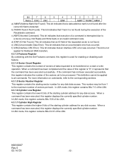
... ,if safety instructions are the cautions and contents described in this manual were thoroughly considered, but also be careful for drive usage in this manual with care to provide information about handling, installation, specifications, principles of operation and interface command implementation.... Handling Page 4 Sec. 1.2, Page 9 - 11 Sec.3.1, Page 14 Sec. 3.2, Page 15 Sec. 3.2, Page 16 Sec. 4.2.1, Page 19 Sec. 4.2.3, Page 21 Sec. 5.1, Page 23 Sec. 5.2, Page 24 K6610007 Rev.5 02.14.'03...
... ,if safety instructions are the cautions and contents described in this manual were thoroughly considered, but also be careful for drive usage in this manual with care to provide information about handling, installation, specifications, principles of operation and interface command implementation.... Handling Page 4 Sec. 1.2, Page 9 - 11 Sec.3.1, Page 14 Sec. 3.2, Page 15 Sec. 3.2, Page 16 Sec. 4.2.1, Page 19 Sec. 4.2.3, Page 21 Sec. 5.1, Page 23 Sec. 5.2, Page 24 K6610007 Rev.5 02.14.'03...
Owners Manual
Page 3
...loss of other products or equipment in resident area 2) Disturbance caused by other than this product Hitachi assumes no event will Hitachi be responsible for products which have been changed by natural disasters, fire, static discharge, misuse,..., neglect, improper handling or installation, unauthorized repair, alteration or accident. IEC60950 A4: 1996 - In general, Hitachi shall not be liable for the electro-magnetic field regulations. 1) Disturbance of operations of data stored on product. CSA... warranty and specific remedies are available to FCC part 15 Class B, etc.).
...loss of other products or equipment in resident area 2) Disturbance caused by other than this product Hitachi assumes no event will Hitachi be responsible for products which have been changed by natural disasters, fire, static discharge, misuse,..., neglect, improper handling or installation, unauthorized repair, alteration or accident. IEC60950 A4: 1996 - In general, Hitachi shall not be liable for the electro-magnetic field regulations. 1) Disturbance of operations of data stored on product. CSA... warranty and specific remedies are available to FCC part 15 Class B, etc.).
Owners Manual
Page 4
...permanent damage to the PCBA of the HDD may cause catastrophic failures. The PCBA side of Metal Head Disk Assembly (HDA) may occur. 15. If non-recommended size screws and torque are not kept within specifications (Power Supply, Environment, etc.). If this manual prior to the ... pins or HDA corners may cause catastrophic failures. Keep usage conditions within the specifications, failures may affect Load/Unload mechanism. 18. Protect the drive from the above condition. 14. Don't open the HDA or break any broken HDA seals. The power supply voltage must not be swapped ...
...permanent damage to the PCBA of the HDD may cause catastrophic failures. The PCBA side of Metal Head Disk Assembly (HDA) may occur. 15. If non-recommended size screws and torque are not kept within specifications (Power Supply, Environment, etc.). If this manual prior to the ... pins or HDA corners may cause catastrophic failures. Keep usage conditions within the specifications, failures may affect Load/Unload mechanism. 18. Protect the drive from the above condition. 14. Don't open the HDA or break any broken HDA seals. The power supply voltage must not be swapped ...
Owners Manual
Page 6
...Sequence 4.0 Installation 4.1 Installation Direction 4.2 Mounting HDD 4.2.1 Mounting HDD with Screws 4.2.2 Single HDD Test Condition 4.2.3 Attention for HDD Installation 4.3 Drive Address Setting(DRIVE 0/DRIVE 1) 4.4 Dimensions 5.0 Packing and Handling 5.1 Packing 5.2 Handling 6.0 Interface 6.1 Power Interface 6.2 Physical Interface 6.2.1 Connector 6.2.2 Connector Pin Assignment...12 Device Control Register Page 2 9 9 10 12 13 13 15 16 17 17 17 17 18 18 19 19 20 21 21 22 23 23 24 25 25 26 26 27 28 ...
...Sequence 4.0 Installation 4.1 Installation Direction 4.2 Mounting HDD 4.2.1 Mounting HDD with Screws 4.2.2 Single HDD Test Condition 4.2.3 Attention for HDD Installation 4.3 Drive Address Setting(DRIVE 0/DRIVE 1) 4.4 Dimensions 5.0 Packing and Handling 5.1 Packing 5.2 Handling 6.0 Interface 6.1 Power Interface 6.2 Physical Interface 6.2.1 Connector 6.2.2 Connector Pin Assignment...12 Device Control Register Page 2 9 9 10 12 13 13 15 16 17 17 17 17 18 18 19 19 20 21 21 22 23 23 24 25 25 26 26 27 28 ...
Owners Manual
Page 15
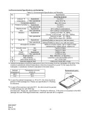
Please see specification 5.1 Packing for reference. K6610007 Rev.5 02.14.'03 - 15 - Ambient temperature 55°C 5°C Temperature at point 10 mm away from the nameplate, a substitution method is -40 to 95 % Maximum wet Operational...bulb 29°C is applied. Item Specification DK23FB-60/40/20 1 Ambient *1 Operational 5 to 55°C temperature Non-operational -40 to 70°C *2 Temperature gradient Max. 20°C /hour 2 Relative humidity Operational 5 to 90 % Non-operational 5 to 0°C, the drive should be packed in the HDD package box with ESD ...
Please see specification 5.1 Packing for reference. K6610007 Rev.5 02.14.'03 - 15 - Ambient temperature 55°C 5°C Temperature at point 10 mm away from the nameplate, a substitution method is -40 to 95 % Maximum wet Operational...bulb 29°C is applied. Item Specification DK23FB-60/40/20 1 Ambient *1 Operational 5 to 55°C temperature Non-operational -40 to 70°C *2 Temperature gradient Max. 20°C /hour 2 Relative humidity Operational 5 to 90 % Non-operational 5 to 0°C, the drive should be packed in the HDD package box with ESD ...
Owners Manual
Page 27
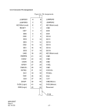
6.2.2 Connector Pin Assignment Figure 6-4 Pin Assignments JUMPER1 A JUMPER3 C KEY(Removed) E RESET- 1 DD7 3 DD6 5 DD5 7 DD4 9 DD3 11 DD2 13 DD1 15 DD0 17 GND 19 DMARQ 21 DIOW- 23 DIOR- 25 IORDY 27 DMACK- 29 INTRQ 31 DA1 33 DA0 35 CS0- 37 DASP- 39 5VDC(...Logic) 41 GND(Logic) 43 B JUMPER0 D JUMPER2 F KEY(Removed) 2 GND 4 DD8 6 DD9 8 DD10 10 DD11 12 DD12 14 DD13 16 DD14 18 DD15 20 KEY(Removed) 22 GND 24 GND 26 GND 28 CSEL 30 GND 32 IOCS16- 34 PDIAG- 36 DA2 38 CS1- 40 GND(Motor) 42 5VDC...
6.2.2 Connector Pin Assignment Figure 6-4 Pin Assignments JUMPER1 A JUMPER3 C KEY(Removed) E RESET- 1 DD7 3 DD6 5 DD5 7 DD4 9 DD3 11 DD2 13 DD1 15 DD0 17 GND 19 DMARQ 21 DIOW- 23 DIOR- 25 IORDY 27 DMACK- 29 INTRQ 31 DA1 33 DA0 35 CS0- 37 DASP- 39 5VDC(...Logic) 41 GND(Logic) 43 B JUMPER0 D JUMPER2 F KEY(Removed) 2 GND 4 DD8 6 DD9 8 DD10 10 DD11 12 DD12 14 DD13 16 DD14 18 DD15 20 KEY(Removed) 22 GND 24 GND 26 GND 28 CSEL 30 GND 32 IOCS16- 34 PDIAG- 36 DA2 38 CS1- 40 GND(Motor) 42 5VDC...
Owners Manual
Page 28
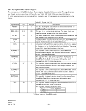
...signal from the device and "O" represents an output signal from the host data bus into a register on the device to configure a device as either DRIVE 0 or DRIVE1 when CSEL mode is ready to receive Ultra DMA Read data . Table 6.2 shows signal definitions. Host asserts this signal, and ...indicates that the host is a 16-bit bi-directional data bus. Both the rising and falling edge latch the data from DD(15:0) into the host. CSEL GND D rive address 0 OPEN 1 *1: Signal name in Figure 6-4 and Table 6.2. 6.2.3 Description of this Read Strobe signal ...
...signal from the device and "O" represents an output signal from the host data bus into a register on the device to configure a device as either DRIVE 0 or DRIVE1 when CSEL mode is ready to receive Ultra DMA Read data . Table 6.2 shows signal definitions. Host asserts this signal, and ...indicates that the host is a 16-bit bi-directional data bus. Both the rising and falling edge latch the data from DD(15:0) into the host. CSEL GND D rive address 0 OPEN 1 *1: Signal name in Figure 6-4 and Table 6.2. 6.2.3 Description of this Read Strobe signal ...
Owners Manual
Page 32
... Data Error): This bit indicates that an interface CRC error was occurred. When a command has been completed and the value of this register contains Bits 15-8 of the LBA. 6.3.1.7 Cylinder High Register This register contains the higher 8 bits of the starting cylinder address for any disk access. In LBA mode, this...
... Data Error): This bit indicates that an interface CRC error was occurred. When a command has been completed and the value of this register contains Bits 15-8 of the LBA. 6.3.1.7 Cylinder High Register This register contains the higher 8 bits of the starting cylinder address for any disk access. In LBA mode, this...
Owners Manual
Page 38
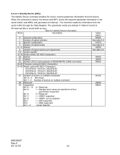
...Number of logical heads 4 - 5 Retired 6 Number of logical sectors per logical track 7-9 Vendor specific 10-19 Serial number (20 ASCII characters) 20 Retired 21 Retired 22 Number of ECC bytes passed on READ/WRITE LONG commands 23-26 Firmware revision(8 ASCII Characters) 27-46 Model...) DK23FB-60: "HITACHI_DK23FB-60" DK23FB-40: "HITACHI_DK23FB-40" DK23FB-20: "HITACHI_DK23FB-20" 47 Number of sectors on multiple commands Bit 15 - 8 80h (fixed) Bit 7 - 0 Number of sectors on multiple command 48 Reserved 49 Capabilities Bit 15 - 14 0 = Reserved Bit 13 1 = Standby timer values as...
...Number of logical heads 4 - 5 Retired 6 Number of logical sectors per logical track 7-9 Vendor specific 10-19 Serial number (20 ASCII characters) 20 Retired 21 Retired 22 Number of ECC bytes passed on READ/WRITE LONG commands 23-26 Firmware revision(8 ASCII Characters) 27-46 Model...) DK23FB-60: "HITACHI_DK23FB-60" DK23FB-40: "HITACHI_DK23FB-40" DK23FB-20: "HITACHI_DK23FB-20" 47 Number of sectors on multiple commands Bit 15 - 8 80h (fixed) Bit 7 - 0 Number of sectors on multiple command 48 Reserved 49 Capabilities Bit 15 - 14 0 = Reserved Bit 13 1 = Standby timer values as...

Owners Manual
Page 39
...of sectors that can be transferred per interrupt on R/W MULTIPLE command 60-61 Total addressable LBA 62 Obsolete 63 Multi-word DMA transfer Bit 15 - 8 Multi-word DMA transfer mode active Bit 7 - 0Multi-word DMA transfer mode supported 64 Flow control PIO transfer Modes supported Bit... Minimum PIO Transfer Cycle Time without Flow Control(ns) 68 Minimum PIO Transfer Cycle Time with IORDY(ns) 69-74 Reserved 75 Queue Depth Bit 15 - 5 0 = Reserved Bit 4 - 0 Maximum queue depth 76-79 Reserved Value (HEX.) 4000h 0200h 0000h 0007h See table 6.6 0000h 0003h 0078h 0078h 00F0h 0078h 0000h ...
...of sectors that can be transferred per interrupt on R/W MULTIPLE command 60-61 Total addressable LBA 62 Obsolete 63 Multi-word DMA transfer Bit 15 - 8 Multi-word DMA transfer mode active Bit 7 - 0Multi-word DMA transfer mode supported 64 Flow control PIO transfer Modes supported Bit... Minimum PIO Transfer Cycle Time without Flow Control(ns) 68 Minimum PIO Transfer Cycle Time with IORDY(ns) 69-74 Reserved 75 Queue Depth Bit 15 - 5 0 = Reserved Bit 4 - 0 Maximum queue depth 76-79 Reserved Value (HEX.) 4000h 0200h 0000h 0007h See table 6.6 0000h 0003h 0078h 0078h 00F0h 0078h 0000h ...
Owners Manual
Page 40
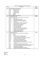
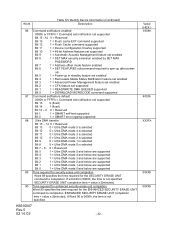
... ATA-2 Bit 1 Obsolete Bit 0 Reserved 81 ATA Interface Minor Version Number 82 Command Set Supported 0000h or FFFFh = Command set notification not supported Bit 15 0 = Reserved Bit 14 1 = NOP command supported Bit 13 1 = READ BUFFER command supported Bit 12 1 = WRITE BUFFER command supported Bit 11... = Supports security feature set Bit 0 1 = Supports SMART feature set 83 Command set supported 0000h or FFFFh = Command set notification not supported Bit 15 0 (fixed) Bit 14 1 (fixed) Bit 13 1 = Flush cache EXT command supported Bit 12 1 = Flush cache command supported Bit 11...
... ATA-2 Bit 1 Obsolete Bit 0 Reserved 81 ATA Interface Minor Version Number 82 Command Set Supported 0000h or FFFFh = Command set notification not supported Bit 15 0 = Reserved Bit 14 1 = NOP command supported Bit 13 1 = READ BUFFER command supported Bit 12 1 = WRITE BUFFER command supported Bit 11... = Supports security feature set Bit 0 1 = Supports SMART feature set 83 Command set supported 0000h or FFFFh = Command set notification not supported Bit 15 0 (fixed) Bit 14 1 (fixed) Bit 13 1 = Flush cache EXT command supported Bit 12 1 = Flush cache command supported Bit 11...
Owners Manual
Page 41
... 41 - Word Table 6.5 Identify Device Information (Continued) Description 84 Command set/feature supported extension 0000h or FFFFh = Command set notification not supported Bit 15 0 (fixed) Bit 14 1 (fixed) Bit 13 - 2 0 = Reserved Bit 1 1 = SMART Self-test supported Bit 0 1 = ...SMART error logging supported 85 Command set/feature enabled 0000h or FFFFh = Command set notification not supported Bit 15 0 = Reserved Bit 14 1 = NOP command supported Bit 13 1 = READ BUFFER command supported Bit 12 1 = WRITE BUFFER command supported Bit 11 0 ...
... 41 - Word Table 6.5 Identify Device Information (Continued) Description 84 Command set/feature supported extension 0000h or FFFFh = Command set notification not supported Bit 15 0 (fixed) Bit 14 1 (fixed) Bit 13 - 2 0 = Reserved Bit 1 1 = SMART Self-test supported Bit 0 1 = ...SMART error logging supported 85 Command set/feature enabled 0000h or FFFFh = Command set notification not supported Bit 15 0 = Reserved Bit 14 1 = NOP command supported Bit 13 1 = READ BUFFER command supported Bit 12 1 = WRITE BUFFER command supported Bit 11 0 ...
Owners Manual
Page 42
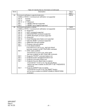
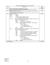
Word Table 6.5 Identify Device Information (Continued) Description 86 Command set/feature enabled 0000h or FFFFh = Command set notification not supported Bit 15 -14 0 = Reserved Bit 13 1 = Flush cache EXT command supported Bit 12 1 = Flush Cache command supported Bit 11 1 = ...Device Configuration Overlay supported Bit 10 1 = 48-bit Address features set supported Bit 9 1 = Automatic Acoustic Management feature set notification not supported Bit 15 0 (fixed) Bit 14 1 (fixed) Bit 13 - 2 0 = Reserved Bit 1 1 = SMART self-test supported Bit 0 1 = SMART error logging supported 88...
Word Table 6.5 Identify Device Information (Continued) Description 86 Command set/feature enabled 0000h or FFFFh = Command set notification not supported Bit 15 -14 0 = Reserved Bit 13 1 = Flush cache EXT command supported Bit 12 1 = Flush Cache command supported Bit 11 1 = ...Device Configuration Overlay supported Bit 10 1 = 48-bit Address features set supported Bit 9 1 = Automatic Acoustic Management feature set notification not supported Bit 15 0 (fixed) Bit 14 1 (fixed) Bit 13 - 2 0 = Reserved Bit 1 1 = SMART self-test supported Bit 0 1 = SMART error logging supported 88...
Owners Manual
Page 43
... DASP- Bit 4 1 = Device 0 detected the assertion of the Master password revision code set when the Master Password was last changed. 93 Hardware reset result Bit 15 0 (fixed) Bit 14 1 (fixed) Bit 13 Bit 12 - 8 1 = Device detected CBLID- Device 1 clears these bits as follows: Bit 12 0 = Reserved Bit 11 1 = Device 1 asserted PDIAG...
... DASP- Bit 4 1 = Device 0 detected the assertion of the Master password revision code set when the Master Password was last changed. 93 Hardware reset result Bit 15 0 (fixed) Bit 14 1 (fixed) Bit 13 Bit 12 - 8 1 = Device detected CBLID- Device 1 clears these bits as follows: Bit 12 0 = Reserved Bit 11 1 = Device 1 asserted PDIAG...
Owners Manual
Page 44
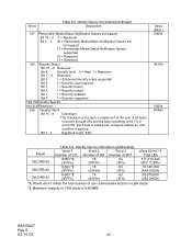
...455MB. Bit 7 - 0 Signature Code "A5h" Value (HEX.) 0000h 0XXXh 0000h XXA5h Model DK23FB-60 DK23FB-40 DK23FB-20 Table 6.6 Identify Device information (Addressing) Word 1 Word 2 Word 3 Number of user addressable sectors in LBA mode. *2. ... Bit 1 - 0 00 = Removable Media Status Notification feature set not support 01 = Removable Media Status Notification feature supported 10 = Reserved 11 = Reserved 128 Security Status Bit 15 - 9 Reserved Bit 8 Security level 0 = High, 1 = Maximum Bit 7 - 6 Reserved Bit 5 1 = Enhanced security erase supported Bit 4 1 = Security count...
...455MB. Bit 7 - 0 Signature Code "A5h" Value (HEX.) 0000h 0XXXh 0000h XXA5h Model DK23FB-60 DK23FB-40 DK23FB-20 Table 6.6 Identify Device information (Addressing) Word 1 Word 2 Word 3 Number of user addressable sectors in LBA mode. *2. ... Bit 1 - 0 00 = Removable Media Status Notification feature set not support 01 = Removable Media Status Notification feature supported 10 = Reserved 11 = Reserved 128 Security Status Bit 15 - 9 Reserved Bit 8 Security level 0 = High, 1 = Maximum Bit 7 - 6 Reserved Bit 5 1 = Enhanced security erase supported Bit 4 1 = Security count...
Owners Manual
Page 54
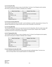
The Sector Count Register sets the standby timer value. 6.3.2.6.4 Idle [97h, E3h] This command causes the device to enter to the Idle Mode. Sector Count Value SC = 0 0 By the power on default, the Standby timer is disabled.
The Sector Count Register sets the standby timer value. 6.3.2.6.4 Idle [97h, E3h] This command causes the device to enter to the Idle Mode. Sector Count Value SC = 0 0 By the power on default, the Standby timer is disabled.

Owners Manual
Page 67
... . Extended error information (Vendor Specific) State This contains a value indicating the state of the device when command was written. Byte n n+1 n+2 n+3 n+4 n+5 n+6 n+7 n+8 ~ n+25 n+27 n+28 ~ n+29 Table 6.15 Error data structure Description Reserved Content of the command data structure is FFh, the content of bytes n+1 through n+11 contains the timestamp. If fewer than...
... . Extended error information (Vendor Specific) State This contains a value indicating the state of the device when command was written. Byte n n+1 n+2 n+3 n+4 n+5 n+6 n+7 n+8 ~ n+25 n+27 n+28 ~ n+29 Table 6.15 Error data structure Description Reserved Content of the command data structure is FFh, the content of bytes n+1 through n+11 contains the timestamp. If fewer than...

Owners Manual
Page 70
... the self-test. This bit shall be written as zeros by the host and the device modifies them as the test progresses. Feature flags bit 15 - 5 Reserved - This bit shall be written as zeros by the host and the device modifies them as the test progresses. Data structure checksum This field...
... the self-test. This bit shall be written as zeros by the host and the device modifies them as the test progresses. Feature flags bit 15 - 5 Reserved - This bit shall be written as zeros by the host and the device modifies them as the test progresses. Data structure checksum This field...
Owners Manual
Page 75
... the device is returned in the device but shall not enable or disable the lock function. Word 0 1-16 17 18 - 255 Contents Control Word Bit 15-9Reserved Bit 8 Security Level 0 = High 1 = Maximum Bit 7 Reserved Bit 0 Identifier 0 = Set user password 1 = Set master password Password(32bytes) Mater Password Revision Code (Valid if word...
... the device is returned in the device but shall not enable or disable the lock function. Word 0 1-16 17 18 - 255 Contents Control Word Bit 15-9Reserved Bit 8 Security Level 0 = High 1 = Maximum Bit 7 Reserved Bit 0 Identifier 0 = Set user password 1 = Set master password Password(32bytes) Mater Password Revision Code (Valid if word...

Owners Manual
Page 76
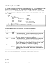
.... The following table defines the content of data from the host. If the device is unlocked have no effect on reset or a hard reset. Security Unlock command issued when the device is in maximum security level then the unlock shall be compared with the stored user password.... K6610007 Rev.5 02.14.'03 - 76 - Word 0 Control Word Bit 15-1Reserved Bit 0 Identifier 1-16 Password(32bytes) 17-255 Reserved Contents 0 = Compare user password 1 = Compare master password If the Identifier bit is ...
.... The following table defines the content of data from the host. If the device is unlocked have no effect on reset or a hard reset. Security Unlock command issued when the device is in maximum security level then the unlock shall be compared with the stored user password.... K6610007 Rev.5 02.14.'03 - 76 - Word 0 Control Word Bit 15-1Reserved Bit 0 Identifier 1-16 Password(32bytes) 17-255 Reserved Contents 0 = Compare user password 1 = Compare master password If the Identifier bit is ...