
Owners Manual
Page 2
... product. (Caution before attempting to the neighboring property ,if safety instructions are not followed. Maximum Power off Interval - Packing - Mounting HDD - Keep this manual with care to provide information about handling, installation, specifications, principles of yourself. z General Caution for Safety The ...) - Not only follow all instructions and cautions indicated throughout this manual were thoroughly considered, but also be careful for drive usage in this manual and the product. z Advise your end user of the safety caution Read and recommend that your...
... product. (Caution before attempting to the neighboring property ,if safety instructions are not followed. Maximum Power off Interval - Packing - Mounting HDD - Keep this manual with care to provide information about handling, installation, specifications, principles of yourself. z General Caution for Safety The ...) - Not only follow all instructions and cautions indicated throughout this manual were thoroughly considered, but also be careful for drive usage in this manual and the product. z Advise your end user of the safety caution Read and recommend that your...
Owners Manual
Page 4
... injury. Do not hit the interface connector pins against other applications that pose a significant risk of the drive should be attached on HDD cover side, the spacing between HDD cover and steel plate should protect the drive from ESD during Power Off only. 9. Hot swapping (Power-on usage conditions, please consult our sales or...
... injury. Do not hit the interface connector pins against other applications that pose a significant risk of the drive should be attached on HDD cover side, the spacing between HDD cover and steel plate should protect the drive from ESD during Power Off only. 9. Hot swapping (Power-on usage conditions, please consult our sales or...
Owners Manual
Page 6
... Normal Load/Unload 3.4.2 Emergency Unload 3.4.3 Required Power Off Sequence 4.0 Installation 4.1 Installation Direction 4.2 Mounting HDD 4.2.1 Mounting HDD with Screws 4.2.2 Single HDD Test Condition 4.2.3 Attention for HDD Installation 4.3 Drive Address Setting(DRIVE 0/DRIVE 1) 4.4 Dimensions 5.0 Packing and Handling 5.1 Packing 5.2 Handling 6.0 Interface 6.1 Power Interface 6.2 Physical ... 9 9 10 12 13 13 15 16 17 17 17 17 18 18 19 19 20 21 21 22 23 23 24 25 25 26 26 27 28 31 31 31 31 ...
... Normal Load/Unload 3.4.2 Emergency Unload 3.4.3 Required Power Off Sequence 4.0 Installation 4.1 Installation Direction 4.2 Mounting HDD 4.2.1 Mounting HDD with Screws 4.2.2 Single HDD Test Condition 4.2.3 Attention for HDD Installation 4.3 Drive Address Setting(DRIVE 0/DRIVE 1) 4.4 Dimensions 5.0 Packing and Handling 5.1 Packing 5.2 Handling 6.0 Interface 6.1 Power Interface 6.2 Physical ... 9 9 10 12 13 13 15 16 17 17 17 17 18 18 19 19 20 21 21 22 23 23 24 25 25 26 26 27 28 31 31 31 31 ...
Owners Manual
Page 15
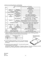
...-40 to 70°C *2 Temperature gradient Max. 20°C /hour 2 Relative humidity Operational 5 to 90 % Non-operational 5 to 0°C, the drive should be measured at point 10 mm away from the nameplate, a substitution method is stipulated in the HDD package box with ESD bag and desiccant, maximum wet...temperature 55°C 5°C Temperature at a point 10 mm away from the nameplate of the maximum wet bulb 40°C , the drive should be packed in HDD package box with retries and ECC) 10 E 13 bits read 9 External magnetic field 1,500 micro Tesla (DC) or less *1 :Ambient...
...-40 to 70°C *2 Temperature gradient Max. 20°C /hour 2 Relative humidity Operational 5 to 90 % Non-operational 5 to 0°C, the drive should be measured at point 10 mm away from the nameplate, a substitution method is stipulated in the HDD package box with ESD bag and desiccant, maximum wet...temperature 55°C 5°C Temperature at a point 10 mm away from the nameplate of the maximum wet bulb 40°C , the drive should be packed in HDD package box with retries and ECC) 10 E 13 bits read 9 External magnetic field 1,500 micro Tesla (DC) or less *1 :Ambient...
Owners Manual
Page 17
....'03 - 17 - The normal unload operation is required for the Host system at Power off , the heads are limited to maximum 20,000 times during HDD life. Sleep Note: Such as explained in Sec. 3.4.2. 3.4.2 Emergency Unload The emergency unload is occurred by unexpected power down, and ...is required by Host system before power off the drive Above sequence is performed by the sequence #1 command, and the command completion normally takes ...
....'03 - 17 - The normal unload operation is required for the Host system at Power off , the heads are limited to maximum 20,000 times during HDD life. Sleep Note: Such as explained in Sec. 3.4.2. 3.4.2 Emergency Unload The emergency unload is occurred by unexpected power down, and ...is required by Host system before power off the drive Above sequence is performed by the sequence #1 command, and the command completion normally takes ...
Owners Manual
Page 19
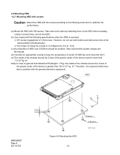
... M3 screws. Take care that the system chassis are flat enough. (d) Consider an appropriate cooling to the HDD when mounting. Therefore, the required inertia level has no problem with the general electronic equipment. inch) (c) Any distortion of the device is greater than 7 ... and side screw hole at the same position simultaneously.) ii) The torque for fixing the screws is 3±0.5kgcm(2.6±0.4 lb. HDD K6610007 Rev.5 02.14.'03 (0.2) Z X Y Figure 4-2 Mounting the HDD - 19 - Note) In case of general Sub-Notebook PC(Weight: 1.7kg), the inertia of the chassis around the Z-axis...
... M3 screws. Take care that the system chassis are flat enough. (d) Consider an appropriate cooling to the HDD when mounting. Therefore, the required inertia level has no problem with the general electronic equipment. inch) (c) Any distortion of the device is greater than 7 ... and side screw hole at the same position simultaneously.) ii) The torque for fixing the screws is 3±0.5kgcm(2.6±0.4 lb. HDD K6610007 Rev.5 02.14.'03 (0.2) Z X Y Figure 4-2 Mounting the HDD - 19 - Note) In case of general Sub-Notebook PC(Weight: 1.7kg), the inertia of the chassis around the Z-axis...
Owners Manual
Page 20
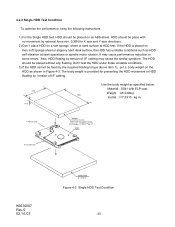
... a soft sponge sheet or hard surface at seek operations or spindle motor rotation. The HDD should be fixed by tension of I =7.3X10⁻⁴ kg m2 ) HDD X Axis Direction K6610007 Rev.5 02.14.'03 ABS-sheet (t = 5mm) Figure 4-3 Single HDD Test Condition - 20 - If the HDD is provided for preventing the HDD movement or HDD floating by external force min...
... a soft sponge sheet or hard surface at seek operations or spindle motor rotation. The HDD should be fixed by tension of I =7.3X10⁻⁴ kg m2 ) HDD X Axis Direction K6610007 Rev.5 02.14.'03 ABS-sheet (t = 5mm) Figure 4-3 Single HDD Test Condition - 20 - If the HDD is provided for preventing the HDD movement or HDD floating by external force min...
Owners Manual
Page 21
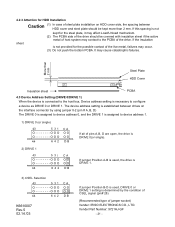
...if the active metal of host system may contact to the PCBA of the drive. The device address setting is established between drives on HDD cover side, the spacing between HDD cover and steel plate should be kept more than 2 mm. If the ...- It may occur. (3) Do not push the bottom PCBA. 4.2.3 Attention for HDD Installation Caution (1) In case of steel plate installation on the interface connector by using jumper 0-2 (pin # A, B, D) The DRIVE 0 is assigned to device address 0, and the DRIVE 1 is assigned to device address 1. 1) DRIVE 0 (or single) 43 5 31 O O O O O O O ...
...if the active metal of host system may contact to the PCBA of the drive. The device address setting is established between drives on HDD cover side, the spacing between HDD cover and steel plate should be kept more than 2 mm. If the ...- It may occur. (3) Do not push the bottom PCBA. 4.2.3 Attention for HDD Installation Caution (1) In case of steel plate installation on the interface connector by using jumper 0-2 (pin # A, B, D) The DRIVE 0 is assigned to device address 0, and the DRIVE 1 is assigned to device address 1. 1) DRIVE 0 (or single) 43 5 31 O O O O O O O ...

Owners Manual
Page 24
It is necessary to prevent vibration, shock, and static electricity to optimize the performance. In particular, prevent vibration or shock generated by dropping, knocking over ) (Hitting) (Hitting) K6610007 Rev.5 02.14.'03 Figure 5-1 - 24 - Also, avoid touching the electrical components directly, which can discharge electrostatic energy and damage the drive. (Dropping) (Knocking over , or hitting the drive. 5.2 Handling Caution Mount the HDD with the screws according to the following instructions to the drive because it will damage the precision parts.
It is necessary to prevent vibration, shock, and static electricity to optimize the performance. In particular, prevent vibration or shock generated by dropping, knocking over ) (Hitting) (Hitting) K6610007 Rev.5 02.14.'03 Figure 5-1 - 24 - Also, avoid touching the electrical components directly, which can discharge electrostatic energy and damage the drive. (Dropping) (Knocking over , or hitting the drive. 5.2 Handling Caution Mount the HDD with the screws according to the following instructions to the drive because it will damage the precision parts.
Owners Manual
Page 26
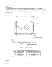
Blocking receptacles Pos.20 of the HDD.) 3.86 mm 2 mm PIN1 PINS REMOVED(KEY) 2 mm K6610007 Rev.5 02.14.'03 PIN44 PIN20 REMOVED(KEY) Figure 6-3 Connector Location Table 6.1 Recommended socket connector Drive interface connector IRISO : 9282B-47Z02-GF or DDK : KKS-PF50A-R33 or equivalent Recommended socket connector IRISO : IMSA-9289S-44A-GF or...
Blocking receptacles Pos.20 of the HDD.) 3.86 mm 2 mm PIN1 PINS REMOVED(KEY) 2 mm K6610007 Rev.5 02.14.'03 PIN44 PIN20 REMOVED(KEY) Figure 6-3 Connector Location Table 6.1 Recommended socket connector Drive interface connector IRISO : 9282B-47Z02-GF or DDK : KKS-PF50A-R33 or equivalent Recommended socket connector IRISO : IMSA-9289S-44A-GF or...
Owners Manual
Page 31
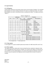
... host system and the device is done through I/O registers. The Control Block Registers are listed in the Status Register. 6.3 Logical Interface 6.3.1 I/O Registers Communication between the HDD's data buffer and the host. 6.3.1.2 Error register This register stores device status when the last command has been completed or diagnostic codes when a self-diagnostic...
... host system and the device is done through I/O registers. The Control Block Registers are listed in the Status Register. 6.3 Logical Interface 6.3.1 I/O Registers Communication between the HDD's data buffer and the host. 6.3.1.2 Error register This register stores device status when the last command has been completed or diagnostic codes when a self-diagnostic...

Owners Manual
Page 111
< Glossary > ATA ABRT AMNF APM BIOS BPI BSY CDR CHS CORR CRC CSS CYL DMA DRV DRDY DRQ DSC DWF ECC ERR GND GB HD HDA HDD I/O ICRC IDE IDNF IDX MB ME2PRML PCBA PIO p-p RPM SC sec SMART SPT SRST TK0NF TPI Typ. UNC AT Attachment Aborted Command AM...Sector Corrected Data Cyclic Redundancy Check Contact Start/Stop Cylinder Direct Memory Accessing Drive Drive Ready Data Request Drive Seek Complete Drive Write Fault Error Checking and Correction Error Ground 1000,000,000 bytes Head Head/Disk Assembly Hard Disk Drive Input/Output Interface CRC Error Intelligent Device Electronics ID Not Found Index 1000...
< Glossary > ATA ABRT AMNF APM BIOS BPI BSY CDR CHS CORR CRC CSS CYL DMA DRV DRDY DRQ DSC DWF ECC ERR GND GB HD HDA HDD I/O ICRC IDE IDNF IDX MB ME2PRML PCBA PIO p-p RPM SC sec SMART SPT SRST TK0NF TPI Typ. UNC AT Attachment Aborted Command AM...Sector Corrected Data Cyclic Redundancy Check Contact Start/Stop Cylinder Direct Memory Accessing Drive Drive Ready Data Request Drive Seek Complete Drive Write Fault Error Checking and Correction Error Ground 1000,000,000 bytes Head Head/Disk Assembly Hard Disk Drive Input/Output Interface CRC Error Intelligent Device Electronics ID Not Found Index 1000...

Owners Manual
Page 112
The following items will be based on the exterior of the factory packaging is indicated on user request. (a) HDD type (b) HDD serial number (c) Package serial number (d) Quantity K6610007 Rev.5 02.14.'03 - 112 - Card Board Silicagel ESD protective bags Quantity 1 1 1 4 50 50 (2) Standard Identification Label The label is described in this reference. (1) Packaging Components No. Factory Packaging The structure of the package. Name 1 Package box 2 HDD Cushion 3 Upper Cushion 4 Side Cushion 5 Desiccant 6 Vinyl Package Materials Card box Card Board Card Board .
The following items will be based on the exterior of the factory packaging is indicated on user request. (a) HDD type (b) HDD serial number (c) Package serial number (d) Quantity K6610007 Rev.5 02.14.'03 - 112 - Card Board Silicagel ESD protective bags Quantity 1 1 1 4 50 50 (2) Standard Identification Label The label is described in this reference. (1) Packaging Components No. Factory Packaging The structure of the package. Name 1 Package box 2 HDD Cushion 3 Upper Cushion 4 Side Cushion 5 Desiccant 6 Vinyl Package Materials Card box Card Board Card Board .


