
Owners Manual
Page 8
... 6.3.2.9.2 Initial Setting of the User Password 73 6.3.2.9.3 Security Mode Operation from Power-on or Hardware Reset 73 6.3.2.9.4 User Password Lost 74 6.3.2.9.5 Security Set Password [F1h] 75 6.3.2.9.6 Security Unlock [F2h] 76 6.3.2.9.7 Security Erase Prepare [F3h] 77 6.3.2.9.8 Security Erase Unit [F4h] 77 6.3.2.9.9 Security Freeze Lock [F5h] 78 6.3.2.9.10 Security Disable Password [F6h] 78...
... 6.3.2.9.2 Initial Setting of the User Password 73 6.3.2.9.3 Security Mode Operation from Power-on or Hardware Reset 73 6.3.2.9.4 User Password Lost 74 6.3.2.9.5 Security Set Password [F1h] 75 6.3.2.9.6 Security Unlock [F2h] 76 6.3.2.9.7 Security Erase Prepare [F3h] 77 6.3.2.9.8 Security Erase Unit [F4h] 77 6.3.2.9.9 Security Freeze Lock [F5h] 78 6.3.2.9.10 Security Disable Password [F6h] 78...

Owners Manual
Page 39
... Cycle Time(ns) 67 Minimum PIO Transfer Cycle Time without Flow Control(ns) 68 Minimum PIO Transfer Cycle Time with IORDY(ns) 69-74 Reserved 75 Queue Depth Bit 15 - 5 0 = Reserved Bit 4 - 0 Maximum queue depth 76-79 Reserved Value (HEX.) 4000h 0200h 0000h 0007h See table 6.6 0000h 0003h 0078h 0078h 00F0h...
... Cycle Time(ns) 67 Minimum PIO Transfer Cycle Time without Flow Control(ns) 68 Minimum PIO Transfer Cycle Time with IORDY(ns) 69-74 Reserved 75 Queue Depth Bit 15 - 5 0 = Reserved Bit 4 - 0 Maximum queue depth 76-79 Reserved Value (HEX.) 4000h 0200h 0000h 0007h See table 6.6 0000h 0003h 0078h 0078h 00F0h...
Owners Manual
Page 75
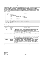
... or hardware reset. Device returns Aborted command error if the device is still stored in Master Password Revision Code field. K6610007 Rev.5 02.14.'03 - 75 - This combination shall set to FFFDh. The security level is revised. 6.3.2.9.5 Security Set Password [F1h] This command requests a transfer of a single sector of information. The...
... or hardware reset. Device returns Aborted command error if the device is still stored in Master Password Revision Code field. K6610007 Rev.5 02.14.'03 - 75 - This combination shall set to FFFDh. The security level is revised. 6.3.2.9.5 Security Set Password [F1h] This command requests a transfer of a single sector of information. The...

Owners Manual
Page 102
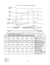
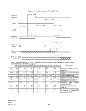
SYMBOL tRFS tRP Mode 0(ns) Mode 1(ns) Mode 2(ns) Mode3(ns) MIN MAX MIN MAX MIN MAX MIN MAX 75 70 60 60 160 125 100 100 Mode4(ns) MIN MAX 60 100 Mode5(ns) Description MIN MAX 50 Ready-to-final STROBE time 85 Ready-to request termination of the Ultra DMA burst no sooner than tRP after HDMARDYis negated. Figure 6-10 Host pausing an Ultra DMA Read DMARQ (device) DMACK(host) STOP tRP (host) HDMARDY(host) tRFS DSTROBE (device) DD(15:0) (device) Note: The host asserts STOP to -pause time K6610007 Rev.5 02.14.'03 - 102 -
SYMBOL tRFS tRP Mode 0(ns) Mode 1(ns) Mode 2(ns) Mode3(ns) MIN MAX MIN MAX MIN MAX MIN MAX 75 70 60 60 160 125 100 100 Mode4(ns) MIN MAX 60 100 Mode5(ns) Description MIN MAX 50 Ready-to-final STROBE time 85 Ready-to request termination of the Ultra DMA burst no sooner than tRP after HDMARDYis negated. Figure 6-10 Host pausing an Ultra DMA Read DMARQ (device) DMACK(host) STOP tRP (host) HDMARDY(host) tRFS DSTROBE (device) DD(15:0) (device) Note: The host asserts STOP to -pause time K6610007 Rev.5 02.14.'03 - 102 -
Owners Manual
Page 103
...MIN MAX MIN MAX MIN MAX MIN MAX MIN MAX tCVS 70 48 31 20 6.7 10 CRC word valid setup time at sender tLI 0 150 0 150 0 150 0 100 0 100 0 75 Limited interlock time tMLI 20 20 20 20 20 20 Interlock time with minimum tAZ 10 10 10 10 10 10 Maximum time ...allowed for output drivers to negation of DMARQ or assertion of DMACK_ tSS 50 50 50 50 50 50 Time from STROBE edge to release tZAH 20 20 20 20 20 20 Minimum delay time...
...MIN MAX MIN MAX MIN MAX MIN MAX MIN MAX tCVS 70 48 31 20 6.7 10 CRC word valid setup time at sender tLI 0 150 0 150 0 150 0 100 0 100 0 75 Limited interlock time tMLI 20 20 20 20 20 20 Interlock time with minimum tAZ 10 10 10 10 10 10 Maximum time ...allowed for output drivers to negation of DMARQ or assertion of DMACK_ tSS 50 50 50 50 50 50 Time from STROBE edge to release tZAH 20 20 20 20 20 20 Minimum delay time...
Owners Manual
Page 104
... definitions for output drivers turning on tRFS 75 70 60 60 60 50 Ready-to-final-STROBE time tRP 160 125 100 100 100 85 Ready-to-pause time tIORDYZ 20 20 20 20 20 20 Maximum time before releasing IORDY tACK 20 20 20 20 20 20 Setup and hold times before assertion and...tLI 0 150 0 150 0 150 0 100 0 100 0 75 Limited interlock time tMLI 20 20 20 20 20 20 Interlock time with minimum tAZ 10 10 10 10 10 10 Maximum time allowed for output drivers to release tZAH 20 20 20 20 20 20 Minimum delay time for the STOP, HDMARDY and DSTROBE signal lines...
... definitions for output drivers turning on tRFS 75 70 60 60 60 50 Ready-to-final-STROBE time tRP 160 125 100 100 100 85 Ready-to-pause time tIORDYZ 20 20 20 20 20 20 Maximum time before releasing IORDY tACK 20 20 20 20 20 20 Setup and hold times before assertion and...tLI 0 150 0 150 0 150 0 100 0 100 0 75 Limited interlock time tMLI 20 20 20 20 20 20 Interlock time with minimum tAZ 10 10 10 10 10 10 Maximum time allowed for output drivers to release tZAH 20 20 20 20 20 20 Minimum delay time for the STOP, HDMARDY and DSTROBE signal lines...

Owners Manual
Page 105
... 20 70 20 70 0 0 0 tACK 20 20 20 tDZFS 70 48 31 Mode3(ns) MIN MAX 20 6.2 0 100 0 20 55 0 20 20 Mode4(ns) MIN MAX 6.7 6.2 0 100 0 20 55 0 20 6.7 Mode5(ns) Description MIN MAX 4.8 Data valid setup time at sender 4.8 Data valid hold time at sender 0 75 Limited interlock time 0 Unlimited interlock 20 50 Envelope time 0 Minimum time before driving IORDY 20 Setup and...
... 20 70 20 70 0 0 0 tACK 20 20 20 tDZFS 70 48 31 Mode3(ns) MIN MAX 20 6.2 0 100 0 20 55 0 20 20 Mode4(ns) MIN MAX 6.7 6.2 0 100 0 20 55 0 20 6.7 Mode5(ns) Description MIN MAX 4.8 Data valid setup time at sender 4.8 Data valid hold time at sender 0 75 Limited interlock time 0 Unlimited interlock 20 50 Envelope time 0 Minimum time before driving IORDY 20 Setup and...

Owners Manual
Page 107
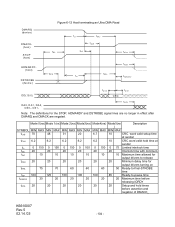
is negated. SYMBOL tRFS tRP Mode 0(ns) Mode 1(ns) Mode 2(ns) MIN MAX MIN MAX MIN MAX 75 70 60 160 125 100 Mode 3(ns) MIN MAX 60 100 Mode 4(ns) Mde5(ns) Description MIN MAX MIN MAX 60 50 Ready-to-final STROBE time 100 85 Ready-to request termination of the Ultra DMA burst no sooner than tRP after DDMARDY- DMARQ (device) DMACK- (host) STOP (host) Figure 6-15 Device pausing an Ultra DMA Write tRP DDMARDY(device) tRFS HSTROBE (host) DD(15:0) (host) Note: The device negates DMARQ to -pause time K6610007 Rev.5 02.14.'03 - 107 -
is negated. SYMBOL tRFS tRP Mode 0(ns) Mode 1(ns) Mode 2(ns) MIN MAX MIN MAX MIN MAX 75 70 60 160 125 100 Mode 3(ns) MIN MAX 60 100 Mode 4(ns) Mde5(ns) Description MIN MAX MIN MAX 60 50 Ready-to-final STROBE time 100 85 Ready-to request termination of the Ultra DMA burst no sooner than tRP after DDMARDY- DMARQ (device) DMACK- (host) STOP (host) Figure 6-15 Device pausing an Ultra DMA Write tRP DDMARDY(device) tRFS HSTROBE (host) DD(15:0) (host) Note: The device negates DMARQ to -pause time K6610007 Rev.5 02.14.'03 - 107 -
Owners Manual
Page 108
... hold time at sender tLI 0 150 0 150 0 150 0 100 0 100 0 75 Limited interlock time tMLI 20 20 20 20 20 20 Interlock time with minimum tAZ 10 10 10 10 10 10 Maximum time allowed for output drivers to release tIORDYZ 20 20 20 20 20 20 Maximum time before releasing IORDY tACK 20 20 20 20 20 20 Setup and hold times for the STOP, DDMARDY and HSTROBE...
... hold time at sender tLI 0 150 0 150 0 150 0 100 0 100 0 75 Limited interlock time tMLI 20 20 20 20 20 20 Interlock time with minimum tAZ 10 10 10 10 10 10 Maximum time allowed for output drivers to release tIORDYZ 20 20 20 20 20 20 Maximum time before releasing IORDY tACK 20 20 20 20 20 20 Setup and hold times for the STOP, DDMARDY and HSTROBE...

Owners Manual
Page 109
... tRP 160 125 100 100 100 85 Ready-to-pause time tIORDYZ 20 20 20 20 20 20 Maximum time before releasing IORDY tACK 20 20 20 20 20 20 Setup and hold time at sender tLI 0 150 0 150 0 150 0 100 0 100 0 75 Limited interlock time tMLI 20 20 20 20 20 20 Interlock time with minimum tRFS 75 70 60 60 60 50 Ready-to-final- Mode 0(ns) Mode...
... tRP 160 125 100 100 100 85 Ready-to-pause time tIORDYZ 20 20 20 20 20 20 Maximum time before releasing IORDY tACK 20 20 20 20 20 20 Setup and hold time at sender tLI 0 150 0 150 0 150 0 100 0 100 0 75 Limited interlock time tMLI 20 20 20 20 20 20 Interlock time with minimum tRFS 75 70 60 60 60 50 Ready-to-final- Mode 0(ns) Mode...