Owners Manual
Page 2
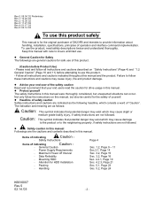
... on this manual, but unexpected situations can occur. Not only follow the instructions on "Safety Instructions" (Page 4) and "1.2 General Caution" (Page 10 and 11) before Product Use) - z Safety caution in this manual Followings are the cautions and contents described in this manual. Packing - z ...Advise your end user of the safety caution Read and recommend that your end users read the caution for drive usage in this manual. z Headline of safety caution Safety instructions and cautions are not followed. Caution: This symbol indicates that potential ...
... on this manual, but unexpected situations can occur. Not only follow the instructions on "Safety Instructions" (Page 4) and "1.2 General Caution" (Page 10 and 11) before Product Use) - z Safety caution in this manual Followings are the cautions and contents described in this manual. Packing - z ...Advise your end user of the safety caution Read and recommend that your end users read the caution for drive usage in this manual. z Headline of safety caution Safety instructions and cautions are not followed. Caution: This symbol indicates that potential ...
Owners Manual
Page 4
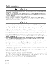
...or seal shall be prepared by dropping, knocking over, or hitting the drive. 16. The power supply voltage must not be swapped during handling. 10. on the cover avoiding the breather hole. If the insulation sheet is max. 10 A for the steel plate, it may contact to active metal of... steel plate installation on swapping) can damage the drive. If non-recommended size screws and torque are not kept within specifications (Power Supply, Environment,...
...or seal shall be prepared by dropping, knocking over, or hitting the drive. 16. The power supply voltage must not be swapped during handling. 10. on the cover avoiding the breather hole. If the insulation sheet is max. 10 A for the steel plate, it may contact to active metal of... steel plate installation on swapping) can damage the drive. If non-recommended size screws and torque are not kept within specifications (Power Supply, Environment,...
Owners Manual
Page 6
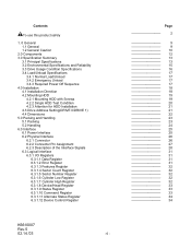
... Installation 4.1 Installation Direction 4.2 Mounting HDD 4.2.1 Mounting HDD with Screws 4.2.2 Single HDD Test Condition 4.2.3 Attention for HDD Installation 4.3 Drive Address Setting(DRIVE 0/DRIVE 1) 4.4 Dimensions 5.0 Packing and Handling 5.1 Packing 5.2 Handling 6.0 Interface 6.1 Power Interface 6.2 Physical Interface 6.2.1 Connector 6.2.2 Connector ... Status Register 6.3.1.10 Command Register 6.3.1.11 Alternate Status Register 6.3.1.12 Device Control Register Page 2 9 9 10 12 13 13 15 16 17 17 17 17 18 18 19 19 20 21 21 22...
... Installation 4.1 Installation Direction 4.2 Mounting HDD 4.2.1 Mounting HDD with Screws 4.2.2 Single HDD Test Condition 4.2.3 Attention for HDD Installation 4.3 Drive Address Setting(DRIVE 0/DRIVE 1) 4.4 Dimensions 5.0 Packing and Handling 5.1 Packing 5.2 Handling 6.0 Interface 6.1 Power Interface 6.2 Physical Interface 6.2.1 Connector 6.2.2 Connector ... Status Register 6.3.1.10 Command Register 6.3.1.11 Alternate Status Register 6.3.1.12 Device Control Register Page 2 9 9 10 12 13 13 15 16 17 17 17 17 18 18 19 19 20 21 21 22...

Owners Manual
Page 7
...] 58 6.3.2.8.7 SMART Return Status [B0h, Sub DAh] 59 6.3.2.8.8 SMART Enable/Disable Attribute AUTOSAVE [B0h, Sub D2h 59 6.3.2.8.9 SMART Save Attribute Values [B0h, Sub D3h] 60 6.3.2.8.10 SMART Enable/Disable Automatic Off-line [B0h, Sub DBh 61 6.3.2.8.11 SMART Execute Off-line Immediate [B0h, Sub D4h 62 K6610007 Rev.5 02.14.'03...
...] 58 6.3.2.8.7 SMART Return Status [B0h, Sub DAh] 59 6.3.2.8.8 SMART Enable/Disable Attribute AUTOSAVE [B0h, Sub D2h 59 6.3.2.8.9 SMART Save Attribute Values [B0h, Sub D3h] 60 6.3.2.8.10 SMART Enable/Disable Automatic Off-line [B0h, Sub DBh 61 6.3.2.8.11 SMART Execute Off-line Immediate [B0h, Sub D4h 62 K6610007 Rev.5 02.14.'03...

Owners Manual
Page 8
...] 78 6.3.2.9.11 Security Mode Command Action [F1h] 79 6.3.2.10 Protected Area Feature, Address Offset Feature 80 6.3.2.10.1 Protected Area Feature and Set Max Security Extension 80 6.3.2.10.2 Address Offset Feature 81 6.3.2.10.3 Read Max Address Command [F8h] 83 6.3.2.10.4 Set Max Address Command [F9h, Sub 00h] 84 6.3.2.10.5 Set Max Set Password Command [F9h, Sub 01h...
...] 78 6.3.2.9.11 Security Mode Command Action [F1h] 79 6.3.2.10 Protected Area Feature, Address Offset Feature 80 6.3.2.10.1 Protected Area Feature and Set Max Security Extension 80 6.3.2.10.2 Address Offset Feature 81 6.3.2.10.3 Read Max Address Command [F8h] 83 6.3.2.10.4 Set Max Address Command [F9h, Sub 00h] 84 6.3.2.10.5 Set Max Set Password Command [F9h, Sub 01h...

Owners Manual
Page 10
Caution (Dropping) PREVENT SHOCKS (Knocking over , or hitting the drive. The drive should be swapped during Power Off only. (c) Shock can result in permanent damage to the following cautions. (a) Warranty void if Metal Head Disk Assembly (HDA) is opened, or any HDA seal/label is broken. (b) Hot swapping (Power on) damages the drive. Prevent shocks often incurred by dropping, knocking over ) (Hitting) (Hitting) K6610007 Rev.5 02.14.'03 Figure 1-1 - 10 - 1.2 General Caution Caution Adhere to the drive and/or loss of data.
Caution (Dropping) PREVENT SHOCKS (Knocking over , or hitting the drive. The drive should be swapped during Power Off only. (c) Shock can result in permanent damage to the following cautions. (a) Warranty void if Metal Head Disk Assembly (HDA) is opened, or any HDA seal/label is broken. (b) Hot swapping (Power on) damages the drive. Prevent shocks often incurred by dropping, knocking over ) (Hitting) (Hitting) K6610007 Rev.5 02.14.'03 Figure 1-1 - 10 - 1.2 General Caution Caution Adhere to the drive and/or loss of data.

Owners Manual
Page 14
... heads are 5.0V and 25°C, respectively. K6610007 Rev.5 02.14.'03 - 14 - This maximum time is required for possible combustion due to 10 seconds in which the power voltage and the temperature are unloaded. *7 :Power mode automatically enters to Low Power Active mode after power-on . Caution ...Voltage rise time 5 - 100 ms at power off. The requirement of this operation occurs, the start up, the drive may have some tolerance after power-on . When this drive and in the nominal condition in case of spin up retry operation. Average of seek is recommended at Low Power Idle...
... heads are 5.0V and 25°C, respectively. K6610007 Rev.5 02.14.'03 - 14 - This maximum time is required for possible combustion due to 10 seconds in which the power voltage and the temperature are unloaded. *7 :Power mode automatically enters to Low Power Active mode after power-on . Caution ...Voltage rise time 5 - 100 ms at power off. The requirement of this operation occurs, the start up, the drive may have some tolerance after power-on . When this drive and in the nominal condition in case of spin up retry operation. Average of seek is recommended at Low Power Idle...
Owners Manual
Page 15
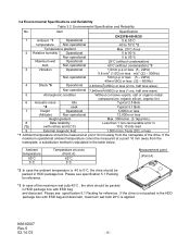
...less Height gradient Max. 300m/min. (3.1kpa/min.) 8 Data reliability Less than 1 non-recoverable error in (*5) (with retries and ECC) 10 E 13 bits read 9 External magnetic field 1,500 micro Tesla (DC) or less *1 :Ambient temperature should be packed in the table ... Reliability No. Item Specification DK23FB-60/40/20 1 Ambient *1 Operational 5 to 55°C temperature Non-operational -40 to 70°C *2 Temperature gradient Max. 20°C /hour 2 Relative humidity Operational 5 to 90 % Non-operational 5 to 0°C, the drive should be measured at cover (Point A) ...
...less Height gradient Max. 300m/min. (3.1kpa/min.) 8 Data reliability Less than 1 non-recoverable error in (*5) (with retries and ECC) 10 E 13 bits read 9 External magnetic field 1,500 micro Tesla (DC) or less *1 :Ambient temperature should be packed in the table ... Reliability No. Item Specification DK23FB-60/40/20 1 Ambient *1 Operational 5 to 55°C temperature Non-operational -40 to 70°C *2 Temperature gradient Max. 20°C /hour 2 Relative humidity Operational 5 to 90 % Non-operational 5 to 0°C, the drive should be measured at cover (Point A) ...
Owners Manual
Page 19
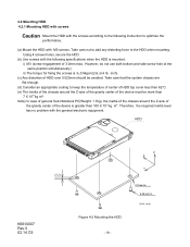
... the same position simultaneously.) ii) The torque for fixing the screws is 3±0.5kgcm(2.6±0.4 lb. inch) (c) Any distortion of the device is greater than 7 X 10⁻⁴ kg m2. HDD K6610007 Rev.5 02.14.'03 (0.2) Z X Y Figure 4-2 Mounting the HDD - 19 - Take care not to add any distorting force to optimize the performance... less than 62°C. (e) The inertia of the chassis around the Z-axis of the gravity center of HDD over 0.020mm should be more than 100 X 10-4 kg m2.
... the same position simultaneously.) ii) The torque for fixing the screws is 3±0.5kgcm(2.6±0.4 lb. inch) (c) Any distortion of the device is greater than 7 X 10⁻⁴ kg m2. HDD K6610007 Rev.5 02.14.'03 (0.2) Z X Y Figure 4-2 Mounting the HDD - 19 - Take care not to add any distorting force to optimize the performance... less than 62°C. (e) The inertia of the chassis around the Z-axis of the gravity center of HDD over 0.020mm should be more than 100 X 10-4 kg m2.
Owners Manual
Page 22
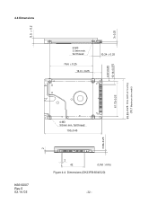
3±0.25 4.07±0.25 10.14±0.375 69.85±0.25 Drive width at mounting (70.1 Maximum drive width) 9.5 ± 0.2 2 4.4 Dimensions 4-M3 3.5mm min. full thread 76.6 ± 0.25 14.0 ± 0.25 10.24 ± 0.25 61.72±0.25 4-M3 3.0mm min. full thread 100±0.45 3.99±0.25 K6610007 Rev.5 02.14.'03 2 42 (Unit : mm) Figure 4-4 Dimensions (DK23FB-60/40/20) - 22 -
3±0.25 4.07±0.25 10.14±0.375 69.85±0.25 Drive width at mounting (70.1 Maximum drive width) 9.5 ± 0.2 2 4.4 Dimensions 4-M3 3.5mm min. full thread 76.6 ± 0.25 14.0 ± 0.25 10.24 ± 0.25 61.72±0.25 4-M3 3.0mm min. full thread 100±0.45 3.99±0.25 K6610007 Rev.5 02.14.'03 2 42 (Unit : mm) Figure 4-4 Dimensions (DK23FB-60/40/20) - 22 -

Owners Manual
Page 25
6.0 Interface 6.1 Power Interface Only +5VDC power is applied to this Device. Typical Spin-up Current Transition 1.6 Current of +5V power 1.4 (A) 1.2 1.0 0.8 0.6 0.4 0.2 0.0 0 1 2 3 4 5 6 7 Time (sec) Figure 6-1 Power Current Transition Typical Spin-up Current Transition with Retry Retry 1.6 Current of +5V power 1.4 (A) 1.2 1.0 0.8 0.6 0.4 0.2 0.0 0 1 2 3 4 5 6 7 8 9 10 11 12 13 14 Time (sec) Figure 6-2 Power Current Transition with retries K6610007 Rev.5 02.14.'03 - 25 - Figures 6-1 and 6-2 show power current transitions after turning on the power.
6.0 Interface 6.1 Power Interface Only +5VDC power is applied to this Device. Typical Spin-up Current Transition 1.6 Current of +5V power 1.4 (A) 1.2 1.0 0.8 0.6 0.4 0.2 0.0 0 1 2 3 4 5 6 7 Time (sec) Figure 6-1 Power Current Transition Typical Spin-up Current Transition with Retry Retry 1.6 Current of +5V power 1.4 (A) 1.2 1.0 0.8 0.6 0.4 0.2 0.0 0 1 2 3 4 5 6 7 8 9 10 11 12 13 14 Time (sec) Figure 6-2 Power Current Transition with retries K6610007 Rev.5 02.14.'03 - 25 - Figures 6-1 and 6-2 show power current transitions after turning on the power.
Owners Manual
Page 27
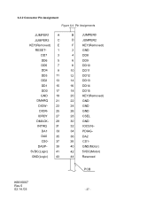
... DA0 35 CS0- 37 DASP- 39 5VDC(Logic) 41 GND(Logic) 43 B JUMPER0 D JUMPER2 F KEY(Removed) 2 GND 4 DD8 6 DD9 8 DD10 10 DD11 12 DD12 14 DD13 16 DD14 18 DD15 20 KEY(Removed) 22 GND 24 GND 26 GND 28 CSEL 30 GND 32 IOCS16- 34 PDIAG- 36 DA2 38 CS1- 40...
... DA0 35 CS0- 37 DASP- 39 5VDC(Logic) 41 GND(Logic) 43 B JUMPER0 D JUMPER2 F KEY(Removed) 2 GND 4 DD8 6 DD9 8 DD10 10 DD11 12 DD12 14 DD13 16 DD14 18 DD15 20 KEY(Removed) 22 GND 24 GND 26 GND 28 CSEL 30 GND 32 IOCS16- 34 PDIAG- 36 DA2 38 CS1- 40...

Owners Manual
Page 33
... selected head is displayed in this register are applied to LBA bits 27 to the description of a command. If the Command Block Registers are returned. 6.3.1.10 Command Register The command code is sent to this bit is not changed until the device gets ready to respond any command. 6.3.1.8 Device/Head Register...
... selected head is displayed in this register are applied to LBA bits 27 to the description of a command. If the Command Block Registers are returned. 6.3.1.10 Command Register The command code is sent to this bit is not changed until the device gets ready to respond any command. 6.3.1.8 Device/Head Register...
Owners Manual
Page 38
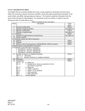
... Specific configuration 3 Number of logical heads 4 - 5 Retired 6 Number of logical sectors per logical track 7-9 Vendor specific 10-19 Serial number (20 ASCII characters) 20 Retired 21 Retired 22 Number of ECC bytes passed on READ/WRITE LONG commands 23-26 Firmware revision(8 ASCII Characters) 27-...46 Model number(40 ASCII Characters) DK23FB-60: "HITACHI_DK23FB-60" DK23FB-40: "HITACHI_DK23FB-40" DK23FB-20: "HITACHI_DK23FB-20" 47 Number of sectors on multiple commands Bit 15 - 8 80h (fixed) Bit 7 - 0 Number of sectors on multiple command...
... Specific configuration 3 Number of logical heads 4 - 5 Retired 6 Number of logical sectors per logical track 7-9 Vendor specific 10-19 Serial number (20 ASCII characters) 20 Retired 21 Retired 22 Number of ECC bytes passed on READ/WRITE LONG commands 23-26 Firmware revision(8 ASCII Characters) 27-...46 Model number(40 ASCII Characters) DK23FB-60: "HITACHI_DK23FB-60" DK23FB-40: "HITACHI_DK23FB-40" DK23FB-20: "HITACHI_DK23FB-20" 47 Number of sectors on multiple commands Bit 15 - 8 80h (fixed) Bit 7 - 0 Number of sectors on multiple command...
Owners Manual
Page 40
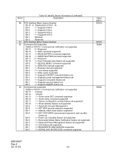
... Bit 14 1 = NOP command supported Bit 13 1 = READ BUFFER command supported Bit 12 1 = WRITE BUFFER command supported Bit 11 0 = Reserved Bit 10 1 = Host Protected Area feature set supported Bit 9 1 = DEVICE RESET command supported Bit 8 1 = SERVICE interrupt supported Bit 7 1 = Release interrupt ...13 1 = Flush cache EXT command supported Bit 12 1 = Flush cache command supported Bit 11 1 = Device configuration overlay feature set supported Bit 10 1 = 48-bit Address feature set supported Bit 9 1 = Automatic Acoustic Management Bit 8 1 = SET MAX security extension supported Bit 7 1...
... Bit 14 1 = NOP command supported Bit 13 1 = READ BUFFER command supported Bit 12 1 = WRITE BUFFER command supported Bit 11 0 = Reserved Bit 10 1 = Host Protected Area feature set supported Bit 9 1 = DEVICE RESET command supported Bit 8 1 = SERVICE interrupt supported Bit 7 1 = Release interrupt ...13 1 = Flush cache EXT command supported Bit 12 1 = Flush cache command supported Bit 11 1 = Device configuration overlay feature set supported Bit 10 1 = 48-bit Address feature set supported Bit 9 1 = Automatic Acoustic Management Bit 8 1 = SET MAX security extension supported Bit 7 1...
Owners Manual
Page 41
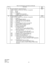
... supported Bit 15 0 = Reserved Bit 14 1 = NOP command supported Bit 13 1 = READ BUFFER command supported Bit 12 1 = WRITE BUFFER command supported Bit 11 0 = Reserved Bit 10 1 = Host Protected Area feature set supported Bit 9 1 = DEVICE RESET command supported Bit 8 1 = SERVICE interrupt enabled Bit 7 1 = Release interrupt enabled Bit 6 1 = Look-ahead enabled If word...
... supported Bit 15 0 = Reserved Bit 14 1 = NOP command supported Bit 13 1 = READ BUFFER command supported Bit 12 1 = WRITE BUFFER command supported Bit 11 0 = Reserved Bit 10 1 = Host Protected Area feature set supported Bit 9 1 = DEVICE RESET command supported Bit 8 1 = SERVICE interrupt enabled Bit 7 1 = Release interrupt enabled Bit 6 1 = Look-ahead enabled If word...
Owners Manual
Page 42
...0 = Reserved Bit 13 1 = Flush cache EXT command supported Bit 12 1 = Flush Cache command supported Bit 11 1 = Device Configuration Overlay supported Bit 10 1 = 48-bit Address features set supported Bit 9 1 = Automatic Acoustic Management feature set enabled Bit 8 1 = SET MAX security extension enabled by SET ...= Reserved Bit 13 0 = Ultra DMA mode 5 is selected Bit 12 0 = Ultra DMA mode 4 is selected Bit 11 0 = Ultra DMA mode 3 is selected Bit 10 0 = Ultra DMA mode 2 is selected Bit 9 0 = Ultra DMA mode 1 is selected Bit 8 0 = Ultra DMA mode 0 is not specified. up Bit 5...
...0 = Reserved Bit 13 1 = Flush cache EXT command supported Bit 12 1 = Flush Cache command supported Bit 11 1 = Device Configuration Overlay supported Bit 10 1 = 48-bit Address features set supported Bit 9 1 = Automatic Acoustic Management feature set enabled Bit 8 1 = SET MAX security extension enabled by SET ...= Reserved Bit 13 0 = Ultra DMA mode 5 is selected Bit 12 0 = Ultra DMA mode 4 is selected Bit 11 0 = Ultra DMA mode 3 is selected Bit 10 0 = Ultra DMA mode 2 is selected Bit 9 0 = Ultra DMA mode 1 is selected Bit 8 0 = Ultra DMA mode 0 is not specified. up Bit 5...
Owners Manual
Page 43
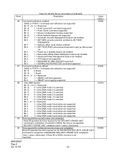
... = Device 0 passed diagnostic Bit 2 - 1 These bits indicate how Device 0 determined the device number: 00, 11 = Reserved 01 = A jumper was used 10 = the CSEL signal was used Bit 0 1 (fixed) 94-126 Reserved Value (HEX.) 40XXh XXXXh XXXXh 0000h K6610007 Rev.5 02.14.'03 - 43 - below ... 15 0 (fixed) Bit 14 1 (fixed) Bit 13 Bit 12 - 8 1 = Device detected CBLID- Bit 10 - 9 These bits indicate how Device 1 determined the device number: 00, 11 = Reserved 01 = A jumper was used 10 = the CSEL signal was used Bit 8 1 (fixed) Bit 7 - 0 Device 0 hardware reset result. Device ...
... = Device 0 passed diagnostic Bit 2 - 1 These bits indicate how Device 0 determined the device number: 00, 11 = Reserved 01 = A jumper was used 10 = the CSEL signal was used Bit 0 1 (fixed) 94-126 Reserved Value (HEX.) 40XXh XXXXh XXXXh 0000h K6610007 Rev.5 02.14.'03 - 43 - below ... 15 0 (fixed) Bit 14 1 (fixed) Bit 13 Bit 12 - 8 1 = Device detected CBLID- Bit 10 - 9 These bits indicate how Device 1 determined the device number: 00, 11 = Reserved 01 = A jumper was used 10 = the CSEL signal was used Bit 8 1 (fixed) Bit 7 - 0 Device 0 hardware reset result. Device ...
Owners Manual
Page 44
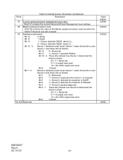
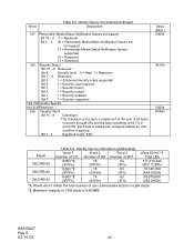
... overflow is 8,455MB. Bit 7 - 0 Signature Code "A5h" Value (HEX.) 0000h 0XXXh 0000h XXA5h Model DK23FB-60 DK23FB-40 DK23FB-20 Table 6.6 Identify Device information (Addressing) Word 1 Word 2 Word 3 Number of bit 7:0 in LBA mode. *2. Word Table 6.5 Identify... set support Bit 15 - 2 0 = Reserved Bit 1 - 0 00 = Removable Media Status Notification feature set not support 01 = Removable Media Status Notification feature supported 10 = Reserved 11 = Reserved 128 Security Status Bit 15 - 9 Reserved Bit 8 Security level 0 = High, 1 = Maximum Bit 7 - 6 Reserved Bit 5 1...
... overflow is 8,455MB. Bit 7 - 0 Signature Code "A5h" Value (HEX.) 0000h 0XXXh 0000h XXA5h Model DK23FB-60 DK23FB-40 DK23FB-20 Table 6.6 Identify Device information (Addressing) Word 1 Word 2 Word 3 Number of bit 7:0 in LBA mode. *2. Word Table 6.5 Identify... set support Bit 15 - 2 0 = Reserved Bit 1 - 0 00 = Removable Media Status Notification feature set not support 01 = Removable Media Status Notification feature supported 10 = Reserved 11 = Reserved 128 Security Status Bit 15 - 9 Reserved Bit 8 Security level 0 = High, 1 = Maximum Bit 7 - 6 Reserved Bit 5 1...
Owners Manual
Page 48
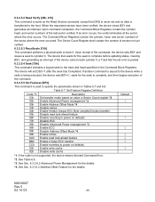
... set and no data is not supported, the device returns Aborted Command Error. *2: See Table 6.8. *3: See Sec. 6.3.2.6.2 Advanced Power Management for the details. *4: See Sec. 6.3.10.2 Address Offset Feature for the details. Upon command completion, the Command Block Registers contain the cylinder, head, and sector numbers of sectors not yet verified...
... set and no data is not supported, the device returns Aborted Command Error. *2: See Table 6.8. *3: See Sec. 6.3.2.6.2 Advanced Power Management for the details. *4: See Sec. 6.3.10.2 Address Offset Feature for the details. Upon command completion, the Command Block Registers contain the cylinder, head, and sector numbers of sectors not yet verified...