Owners Manual
Page 1
K6610007 Rev.5 02.14.'03 H I T A C H I All Rights Reserved, Copyright ©2002-2003 Hitachi, Ltd. (Total 113 pages) - 1 - Read and recommend drive usage cautions to your end user. Keep this manual with care. OEM Manual DK23FB-60/40/20 Disk Drive Specifications REV.5 Caution for Safety Read Safety descriptions carefully.
K6610007 Rev.5 02.14.'03 H I T A C H I All Rights Reserved, Copyright ©2002-2003 Hitachi, Ltd. (Total 113 pages) - 1 - Read and recommend drive usage cautions to your end user. Keep this manual with care. OEM Manual DK23FB-60/40/20 Disk Drive Specifications REV.5 Caution for Safety Read Safety descriptions carefully.
Owners Manual
Page 5
... or accidental power loss during write operation. Data may be lost due to ensure that the information provided herein is packed in a box. 20. Hitachi does not perform data recovery. 23. To prepare for any person of an error or inconsistency. NOTE TO USERS While every effort has been... made to accidents such as disasters, shock damage during drive transportation to protect from any damage. 22. Recorded data on the disk may be lost due to the contents hereof and specifically disclaims ...
... or accidental power loss during write operation. Data may be lost due to ensure that the information provided herein is packed in a box. 20. Hitachi does not perform data recovery. 23. To prepare for any person of an error or inconsistency. NOTE TO USERS While every effort has been... made to accidents such as disasters, shock damage during drive transportation to protect from any damage. 22. Recorded data on the disk may be lost due to the contents hereof and specifically disclaims ...
Owners Manual
Page 6
... Off Sequence 4.0 Installation 4.1 Installation Direction 4.2 Mounting HDD 4.2.1 Mounting HDD with Screws 4.2.2 Single HDD Test Condition 4.2.3 Attention for HDD Installation 4.3 Drive Address Setting(DRIVE 0/DRIVE 1) 4.4 Dimensions 5.0 Packing and Handling 5.1 Packing 5.2 Handling 6.0 Interface 6.1 Power Interface 6.2 Physical Interface 6.2.1 Connector 6.2.2 Connector Pin Assignment 6.2.3...2 9 9 10 12 13 13 15 16 17 17 17 17 18 18 19 19 20 21 21 22 23 23 24 25 25 26 26 27 28 31 31 31 31 32...
... Off Sequence 4.0 Installation 4.1 Installation Direction 4.2 Mounting HDD 4.2.1 Mounting HDD with Screws 4.2.2 Single HDD Test Condition 4.2.3 Attention for HDD Installation 4.3 Drive Address Setting(DRIVE 0/DRIVE 1) 4.4 Dimensions 5.0 Packing and Handling 5.1 Packing 5.2 Handling 6.0 Interface 6.1 Power Interface 6.2 Physical Interface 6.2.1 Connector 6.2.2 Connector Pin Assignment 6.2.3...2 9 9 10 12 13 13 15 16 17 17 17 17 18 18 19 19 20 21 21 22 23 23 24 25 25 26 26 27 28 31 31 31 31 32...
Owners Manual
Page 9
Model DK23FB-60 DK23FB-40 DK23FB-20 Capacity (Formatted) 60.011 GB 40.007 GB 20.003 GB Height 9.5 mm 9.5 mm 9.5 mm Interface ATA-5(IDE) ATA-5(IDE) ATA-5(IDE) [Features] - On-the-fly ECC Correction - Operating Shock 2,450m/S2(250G, 2ms... MCC 2.5 inch Small Form Factor(9.5mm height) [Identify Device Information for 9.5mm height) in CHS mode is 8,455MB. 1.0 General 1.1 Introduction The DK23FB series disk drives reach high capacities (60/40/20GB for Setup] Table 1.1 Identify Device information (Addressing) Model Word 1 Word 3 Word 6 Number of SPT DK23FB-60 16383 (*1) 16...
Model DK23FB-60 DK23FB-40 DK23FB-20 Capacity (Formatted) 60.011 GB 40.007 GB 20.003 GB Height 9.5 mm 9.5 mm 9.5 mm Interface ATA-5(IDE) ATA-5(IDE) ATA-5(IDE) [Features] - On-the-fly ECC Correction - Operating Shock 2,450m/S2(250G, 2ms... MCC 2.5 inch Small Form Factor(9.5mm height) [Identify Device Information for 9.5mm height) in CHS mode is 8,455MB. 1.0 General 1.1 Introduction The DK23FB series disk drives reach high capacities (60/40/20GB for Setup] Table 1.1 Identify Device information (Addressing) Model Word 1 Word 3 Word 6 Number of SPT DK23FB-60 16383 (*1) 16...
Owners Manual
Page 12
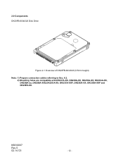
2.0 Components DK23FB-60/40/20 Disk Drive Figure 2-1 Overview of DK23FB-60/40/20 (9.5mm height) Note: 1) Prepare connection cables referring to Sec. 6.2. 2) Mounting holes are compatible with DK237A-XX, DK238A-XX, DK239A-XX, DK23AA-XX, DK23BA-xx, DK23BA-XXE,DK23CA-XX, DK23CA-XXF, DK23DA-XX, DK23DA-XXF and DK23EX-XX. K6610007 Rev.5 02.14.'03 - 12 -
2.0 Components DK23FB-60/40/20 Disk Drive Figure 2-1 Overview of DK23FB-60/40/20 (9.5mm height) Note: 1) Prepare connection cables referring to Sec. 6.2. 2) Mounting holes are compatible with DK237A-XX, DK238A-XX, DK239A-XX, DK23AA-XX, DK23BA-xx, DK23BA-XXE,DK23CA-XX, DK23CA-XXF, DK23DA-XX, DK23DA-XXF and DK23EX-XX. K6610007 Rev.5 02.14.'03 - 12 -

Owners Manual
Page 13
...) - Ready *2 5 (Typical) *3 sec Sleep/Standby - 3.0 Specification Summary 3.1 Principal Specifications Table 3.1 Principal Specifications Specifications No. Item DK23FB-60 DK23FB-40 DK23FB-20 Units 1 Capacity per drive (Formatted) 60.011 40.007 20.003 GB Capacity per sector 512 Bytes Disks 2 1 Heads 4 3 2 Cylinders 42518 2 Seek time Average 13 *1 ms (Nominal Maximum 24 *1 ms value) Minimum 3 ms...
...) - Ready *2 5 (Typical) *3 sec Sleep/Standby - 3.0 Specification Summary 3.1 Principal Specifications Table 3.1 Principal Specifications Specifications No. Item DK23FB-60 DK23FB-40 DK23FB-20 Units 1 Capacity per drive (Formatted) 60.011 40.007 20.003 GB Capacity per sector 512 Bytes Disks 2 1 Heads 4 3 2 Cylinders 42518 2 Seek time Average 13 *1 ms (Nominal Maximum 24 *1 ms value) Minimum 3 ms...
Owners Manual
Page 15
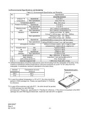
...to 55°C temperature Non-operational -40 to 70°C *2 Temperature gradient Max. 20°C /hour 2 Relative humidity Operational 5 to 90 % Non-operational 5 to 0°C, the drive should be measured at point 10 mm away from the nameplate, a substitution method is not... packed in HDD package box. Please see specification 5.1 Packing for reference. *3 :In case of the drive. K6610007 Rev.5 02.14.'03 - 15 - 3.2 Environmental Specifications and Reliability Table 3.2 Environmental Specification and Reliability No. organic silicon, organic...
...to 55°C temperature Non-operational -40 to 70°C *2 Temperature gradient Max. 20°C /hour 2 Relative humidity Operational 5 to 90 % Non-operational 5 to 0°C, the drive should be measured at point 10 mm away from the nameplate, a substitution method is not... packed in HDD package box. Please see specification 5.1 Packing for reference. *3 :In case of the drive. K6610007 Rev.5 02.14.'03 - 15 - 3.2 Environmental Specifications and Reliability Table 3.2 Environmental Specification and Reliability No. organic silicon, organic...
Owners Manual
Page 16
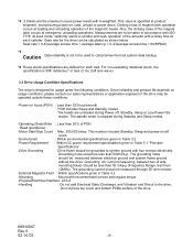
...drive. For non-operating rotational shock, the specification is 50K radian/sec2 or less (2 ms, half sine wave). 3.3 Drive Usage Condition Specifications The drive...*6 :These shock specifications are defined for the drive can be less than 50 mAp-p (Frequency...drive. Seek rate for each cylinder. Grounding AC current (measuring between electrical ground and system frame ground without the drive...given in Table 3.1 "Principal Specifications" -Drive Grounding : Drive frame should be measured through 50 ohm ...representatives or application engineers if the drive may be used to be ...
...drive. For non-operating rotational shock, the specification is 50K radian/sec2 or less (2 ms, half sine wave). 3.3 Drive Usage Condition Specifications The drive...*6 :These shock specifications are defined for the drive can be less than 50 mAp-p (Frequency...drive. Seek rate for each cylinder. Grounding AC current (measuring between electrical ground and system frame ground without the drive...given in Table 3.1 "Principal Specifications" -Drive Grounding : Drive frame should be measured through 50 ohm ...representatives or application engineers if the drive may be used to be ...
Owners Manual
Page 17
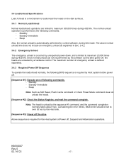
...performed by the software control after power off, the heads are limited to over 30 sec by the Host side. [Sequence #3]: Power off the drive Above sequence is required for the Host system at Power off . [Sequence #1]: Execute one of emergency unload is defined separately. 3.4.3 Required Power Off... life. K6610007 Rev.5 02.14.'03 - 17 - Sleep Also, the normal unload is unload by unexpected power down, and is limited to maximum 20,000 times during Idle mode. Standby Immediate - Standby - Standby - The above normal unload time does not include an emergency unload as Soft Reset, Flush...
...performed by the software control after power off, the heads are limited to over 30 sec by the Host side. [Sequence #3]: Power off the drive Above sequence is required for the Host system at Power off . [Sequence #1]: Execute one of emergency unload is defined separately. 3.4.3 Required Power Off... life. K6610007 Rev.5 02.14.'03 - 17 - Sleep Also, the normal unload is unload by unexpected power down, and is limited to maximum 20,000 times during Idle mode. Standby Immediate - Standby - Standby - The above normal unload time does not include an emergency unload as Soft Reset, Flush...
Owners Manual
Page 18
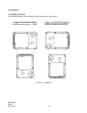
4.0 Installation 4.1 Installation Direction The DK23FB-60/40/20 can be installed in the 6 directions as shown below. K6610007 Rev.5 02.14.'03 Figure 4-1 Installation - 18 -
4.0 Installation 4.1 Installation Direction The DK23FB-60/40/20 can be installed in the 6 directions as shown below. K6610007 Rev.5 02.14.'03 Figure 4-1 Installation - 18 -
Owners Manual
Page 20
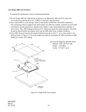
...HDD self-vibration at HDD test. Also, HDD floating by the required holding torque above item 1), put a body weight on a soft sponge sheet or hard surface at seek operations or spindle motor rotation. The HDD should be fixed by tension of I =7.3X10⁻⁴ kg m2 ) HDD X Axis Direction K6610007 ...Rev.5 02.14.'03 ABS-sheet (t = 5mm) Figure 4-3 Single HDD Test Condition - 20 - If the HDD is provided for preventing the HDD movement or HDD floating by external force min. 0.39N for X axis and Y-axis directions. 2) Don't place...
...HDD self-vibration at HDD test. Also, HDD floating by the required holding torque above item 1), put a body weight on a soft sponge sheet or hard surface at seek operations or spindle motor rotation. The HDD should be fixed by tension of I =7.3X10⁻⁴ kg m2 ) HDD X Axis Direction K6610007 ...Rev.5 02.14.'03 ABS-sheet (t = 5mm) Figure 4-3 Single HDD Test Condition - 20 - If the HDD is provided for preventing the HDD movement or HDD floating by external force min. 0.39N for X axis and Y-axis directions. 2) Don't place...
Owners Manual
Page 22
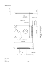
full thread 100±0.45 3.99±0.25 K6610007 Rev.5 02.14.'03 2 42 (Unit : mm) Figure 4-4 Dimensions (DK23FB-60/40/20) - 22 - 3±0.25 4.07±0.25 10.14±0.375 69.85±0.25 Drive width at mounting (70.1 Maximum drive width) 9.5 ± 0.2 2 4.4 Dimensions 4-M3 3.5mm min. full thread 76.6 ± 0.25 14.0 ± 0.25 10.24 ± 0.25 61.72±0.25 4-M3 3.0mm min.
full thread 100±0.45 3.99±0.25 K6610007 Rev.5 02.14.'03 2 42 (Unit : mm) Figure 4-4 Dimensions (DK23FB-60/40/20) - 22 - 3±0.25 4.07±0.25 10.14±0.375 69.85±0.25 Drive width at mounting (70.1 Maximum drive width) 9.5 ± 0.2 2 4.4 Dimensions 4-M3 3.5mm min. full thread 76.6 ± 0.25 14.0 ± 0.25 10.24 ± 0.25 61.72±0.25 4-M3 3.0mm min.
Owners Manual
Page 26
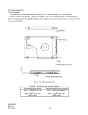
...to pin of connector or blow out fuse of socket connector is recommended to prevent wrong insertion. (It is shown in Figure 6-3. Blocking receptacles Pos.20 of the HDD.) 3.86 mm 2 mm PIN1 PINS REMOVED(KEY) 2 mm K6610007 Rev.5 02.14.'03 PIN44 PIN20 REMOVED(KEY) Figure 6-3 ...Connector Location Table 6.1 Recommended socket connector Drive interface connector IRISO : 9282B-47Z02-GF or DDK : KKS-PF50A-R33 or equivalent Recommended socket connector IRISO : IMSA-9289S-44A-GF or DDK : KKS...
...to pin of connector or blow out fuse of socket connector is recommended to prevent wrong insertion. (It is shown in Figure 6-3. Blocking receptacles Pos.20 of the HDD.) 3.86 mm 2 mm PIN1 PINS REMOVED(KEY) 2 mm K6610007 Rev.5 02.14.'03 PIN44 PIN20 REMOVED(KEY) Figure 6-3 ...Connector Location Table 6.1 Recommended socket connector Drive interface connector IRISO : 9282B-47Z02-GF or DDK : KKS-PF50A-R33 or equivalent Recommended socket connector IRISO : IMSA-9289S-44A-GF or DDK : KKS...
Owners Manual
Page 27
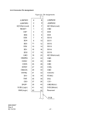
...- 39 5VDC(Logic) 41 GND(Logic) 43 B JUMPER0 D JUMPER2 F KEY(Removed) 2 GND 4 DD8 6 DD9 8 DD10 10 DD11 12 DD12 14 DD13 16 DD14 18 DD15 20 KEY(Removed) 22 GND 24 GND 26 GND 28 CSEL 30 GND 32 IOCS16- 34 PDIAG- 36 DA2 38 CS1- 40 GND(Motor) 42 5VDC...
...- 39 5VDC(Logic) 41 GND(Logic) 43 B JUMPER0 D JUMPER2 F KEY(Removed) 2 GND 4 DD8 6 DD9 8 DD10 10 DD11 12 DD12 14 DD13 16 DD14 18 DD15 20 KEY(Removed) 22 GND 24 GND 26 GND 28 CSEL 30 GND 32 IOCS16- 34 PDIAG- 36 DA2 38 CS1- 40 GND(Motor) 42 5VDC...
Owners Manual
Page 30
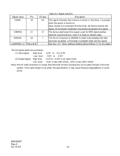
...signal. See Sec. 4.3 " Drive Address Setting (Drive 0/Drive 1)" for DMA data transfers between host and device, when it may cause factional degradations or some errors. DMARQ DMACKJUMPER0,1,2 Pin 39 21 29 PIN-A,B,D I/O type I/O O I /F cable should be no longer than 50cm(20 inches) including the circuit pattern ...length in response to DMARQ to either acknowledge that data has been accepted, or that Drive 1 is present when the power is ready to +5.25V or an open circuit Low...
...signal. See Sec. 4.3 " Drive Address Setting (Drive 0/Drive 1)" for DMA data transfers between host and device, when it may cause factional degradations or some errors. DMARQ DMACKJUMPER0,1,2 Pin 39 21 29 PIN-A,B,D I/O type I/O O I /F cable should be no longer than 50cm(20 inches) including the circuit pattern ...length in response to DMARQ to either acknowledge that data has been accepted, or that Drive 1 is present when the power is ready to +5.25V or an open circuit Low...
Owners Manual
Page 38
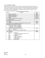
... 3 Number of logical heads 4 - 5 Retired 6 Number of logical sectors per logical track 7-9 Vendor specific 10-19 Serial number (20 ASCII characters) 20 Retired 21 Retired 22 Number of ECC bytes passed on READ/WRITE LONG commands 23-26 Firmware revision(8 ASCII Characters) 27-46 Model number...(40 ASCII Characters) DK23FB-60: "HITACHI_DK23FB-60" DK23FB-40: "HITACHI_DK23FB-40" DK23FB-20: "HITACHI_DK23FB-20" 47 Number of sectors on multiple commands Bit 15 - 8 80h (fixed) Bit 7 - 0 Number of sectors on multiple command 48 ...
... 3 Number of logical heads 4 - 5 Retired 6 Number of logical sectors per logical track 7-9 Vendor specific 10-19 Serial number (20 ASCII characters) 20 Retired 21 Retired 22 Number of ECC bytes passed on READ/WRITE LONG commands 23-26 Firmware revision(8 ASCII Characters) 27-46 Model number...(40 ASCII Characters) DK23FB-60: "HITACHI_DK23FB-60" DK23FB-40: "HITACHI_DK23FB-40" DK23FB-20: "HITACHI_DK23FB-20" 47 Number of sectors on multiple commands Bit 15 - 8 80h (fixed) Bit 7 - 0 Number of sectors on multiple command 48 ...
Owners Manual
Page 44
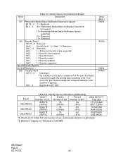
Bit 7 - 0 Signature Code "A5h" Value (HEX.) 0000h 0XXXh 0000h XXA5h Model DK23FB-60 DK23FB-40 DK23FB-20 Table 6.6 Identify Device information (Addressing) Word 1 Word 2 Word 3 Number of user addressable sectors in word 255. K6610007 Rev.5 02.14.'03 - 44 - Number of HD ...
Bit 7 - 0 Signature Code "A5h" Value (HEX.) 0000h 0XXXh 0000h XXA5h Model DK23FB-60 DK23FB-40 DK23FB-20 Table 6.6 Identify Device information (Addressing) Word 1 Word 2 Word 3 Number of user addressable sectors in word 255. K6610007 Rev.5 02.14.'03 - 44 - Number of HD ...
Owners Manual
Page 54
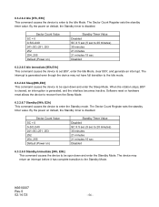
6.3.2.6.4 Idle [97h, E3h] This command causes the device to enter to the Idle Mode. By the power on default, the Standby timer is disabled. The Sector Count Register sets the standby timer value. Sector Count Value SC = 0 0
6.3.2.6.4 Idle [97h, E3h] This command causes the device to enter to the Idle Mode. By the power on default, the Standby timer is disabled. The Sector Count Register sets the standby timer value. Sector Count Value SC = 0 0
Owners Manual
Page 77
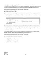
... be completed immediately prior to the Security Erase Unit command. DK23FB-60 : - Device returns Aborted command error if the device is set. DK23FB-40 : - DK23FB-20 : 44 minutes 28 minutes 12 minutes K6610007 Rev.5 02.14.'03 - 77 - If the password does not match, then the device rejects the command with...
... be completed immediately prior to the Security Erase Unit command. DK23FB-60 : - Device returns Aborted command error if the device is set. DK23FB-40 : - DK23FB-20 : 44 minutes 28 minutes 12 minutes K6610007 Rev.5 02.14.'03 - 77 - If the password does not match, then the device rejects the command with...
Owners Manual
Page 85
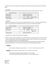
... Sector Number - In case of maximum LBA in LBA mode, the Number of logical cylinder of current cylinders is not used for DK23FB-60/40/20. The data returned in the command block registers is (maximum LBA)/(16 x 63) for the Maximum LBA in the device.
... Sector Number - In case of maximum LBA in LBA mode, the Number of logical cylinder of current cylinders is not used for DK23FB-60/40/20. The data returned in the command block registers is (maximum LBA)/(16 x 63) for the Maximum LBA in the device.