Owners Manual
Page 1
Keep this manual with care. K6610007 Rev.5 02.14.'03 H I T A C H I All Rights Reserved, Copyright ©2002-2003 Hitachi, Ltd. (Total 113 pages) - 1 - OEM Manual DK23FB-60/40/20 Disk Drive Specifications REV.5 Caution for Safety Read Safety descriptions carefully. Read and recommend drive usage cautions to your end user.
Keep this manual with care. K6610007 Rev.5 02.14.'03 H I T A C H I All Rights Reserved, Copyright ©2002-2003 Hitachi, Ltd. (Total 113 pages) - 1 - OEM Manual DK23FB-60/40/20 Disk Drive Specifications REV.5 Caution for Safety Read Safety descriptions carefully. Read and recommend drive usage cautions to your end user.
Owners Manual
Page 5
...us in a box. 20. To prepare for the drive transportation) 21. To returning over 100 units, use original outside package with pallet or proper packaging with respect to ensure that the information provided herein is packed in the event of such revisions or changes. Hitachi does not perform data... disclaims any implied warranties or merchantability or fitness for any damage. (Keep some extra packages for accidents, back up data. Further Hitachi reserves the right to revise this publication and to make changes from time to time in the content hereof without obligation to protect ...
...us in a box. 20. To prepare for the drive transportation) 21. To returning over 100 units, use original outside package with pallet or proper packaging with respect to ensure that the information provided herein is packed in the event of such revisions or changes. Hitachi does not perform data... disclaims any implied warranties or merchantability or fitness for any damage. (Keep some extra packages for accidents, back up data. Further Hitachi reserves the right to revise this publication and to make changes from time to time in the content hereof without obligation to protect ...
Owners Manual
Page 6
... Off Sequence 4.0 Installation 4.1 Installation Direction 4.2 Mounting HDD 4.2.1 Mounting HDD with Screws 4.2.2 Single HDD Test Condition 4.2.3 Attention for HDD Installation 4.3 Drive Address Setting(DRIVE 0/DRIVE 1) 4.4 Dimensions 5.0 Packing and Handling 5.1 Packing 5.2 Handling 6.0 Interface 6.1 Power Interface 6.2 Physical Interface 6.2.1 Connector 6.2.2 Connector Pin Assignment 6.2.3...2 9 9 10 12 13 13 15 16 17 17 17 17 18 18 19 19 20 21 21 22 23 23 24 25 25 26 26 27 28 31 31 31 31 32...
... Off Sequence 4.0 Installation 4.1 Installation Direction 4.2 Mounting HDD 4.2.1 Mounting HDD with Screws 4.2.2 Single HDD Test Condition 4.2.3 Attention for HDD Installation 4.3 Drive Address Setting(DRIVE 0/DRIVE 1) 4.4 Dimensions 5.0 Packing and Handling 5.1 Packing 5.2 Handling 6.0 Interface 6.1 Power Interface 6.2 Physical Interface 6.2.1 Connector 6.2.2 Connector Pin Assignment 6.2.3...2 9 9 10 12 13 13 15 16 17 17 17 17 18 18 19 19 20 21 21 22 23 23 24 25 25 26 26 27 28 31 31 31 31 32...
Owners Manual
Page 9
...The DK23FB series disk drives reach high capacities (60/40/20GB for Setup] Table 1.1 Identify Device information (Addressing) Model Word 1 Word 3 Word 6 Number of SPT DK23FB-60 16383 (*1) 16 63 (3FFFh) (0010h) (3Fh) DK23FB-40 16383 (*1) 16 63 (3FFFh) (0010h) (3Fh) DK23FB-20 16383 (*1) 16 63 ... height) [Identify Device Information for 9.5mm height) in CHS mode is 8,455MB. Model DK23FB-60 DK23FB-40 DK23FB-20 Capacity (Formatted) 60.011 GB 40.007 GB 20.003 GB Height 9.5 mm 9.5 mm 9.5 mm Interface ATA-5(IDE) ATA-5(IDE) ATA-5(IDE) [Features] - ME2PRML Read Channel...
...The DK23FB series disk drives reach high capacities (60/40/20GB for Setup] Table 1.1 Identify Device information (Addressing) Model Word 1 Word 3 Word 6 Number of SPT DK23FB-60 16383 (*1) 16 63 (3FFFh) (0010h) (3Fh) DK23FB-40 16383 (*1) 16 63 (3FFFh) (0010h) (3Fh) DK23FB-20 16383 (*1) 16 63 ... height) [Identify Device Information for 9.5mm height) in CHS mode is 8,455MB. Model DK23FB-60 DK23FB-40 DK23FB-20 Capacity (Formatted) 60.011 GB 40.007 GB 20.003 GB Height 9.5 mm 9.5 mm 9.5 mm Interface ATA-5(IDE) ATA-5(IDE) ATA-5(IDE) [Features] - ME2PRML Read Channel...
Owners Manual
Page 12
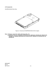
2.0 Components DK23FB-60/40/20 Disk Drive Figure 2-1 Overview of DK23FB-60/40/20 (9.5mm height) Note: 1) Prepare connection cables referring to Sec. 6.2. 2) Mounting holes are compatible with DK237A-XX, DK238A-XX, DK239A-XX, DK23AA-XX, DK23BA-xx, DK23BA-XXE,DK23CA-XX, DK23CA-XXF, DK23DA-XX, DK23DA-XXF and DK23EX-XX. K6610007 Rev.5 02.14.'03 - 12 -
2.0 Components DK23FB-60/40/20 Disk Drive Figure 2-1 Overview of DK23FB-60/40/20 (9.5mm height) Note: 1) Prepare connection cables referring to Sec. 6.2. 2) Mounting holes are compatible with DK237A-XX, DK238A-XX, DK239A-XX, DK23AA-XX, DK23BA-xx, DK23BA-XXE,DK23CA-XX, DK23CA-XXF, DK23DA-XX, DK23DA-XXF and DK23EX-XX. K6610007 Rev.5 02.14.'03 - 12 -

Owners Manual
Page 13
...-p or less 0.9 A(4.5W) 0.17 A(0.85W) grams - Sleep 0.02 A(0.1W) K6610007 Rev.5 02.14.'03 - 13 - Item DK23FB-60 DK23FB-40 DK23FB-20 Units 1 Capacity per drive (Formatted) 60.011 40.007 20.003 GB Capacity per sector 512 Bytes Disks 2 1 Heads 4 3 2 Cylinders 42518 2 Seek time Average 13 *1 ms (Nominal Maximum 24 *1 ms value) Minimum...
...-p or less 0.9 A(4.5W) 0.17 A(0.85W) grams - Sleep 0.02 A(0.1W) K6610007 Rev.5 02.14.'03 - 13 - Item DK23FB-60 DK23FB-40 DK23FB-20 Units 1 Capacity per drive (Formatted) 60.011 40.007 20.003 GB Capacity per sector 512 Bytes Disks 2 1 Heads 4 3 2 Cylinders 42518 2 Seek time Average 13 *1 ms (Nominal Maximum 24 *1 ms value) Minimum...
Owners Manual
Page 15
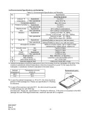
...Environmental Specification and Reliability No. Please see specification 5.1 Packing for reference. *3 :In case of the maximum wet bulb 40°C , the drive should be measured at point 10 mm away from the nameplate, a substitution method is -40 to 95 % Maximum wet Operational 29°C... 5 to 55°C temperature Non-operational -40 to 70°C *2 Temperature gradient Max. 20°C /hour 2 Relative humidity Operational 5 to 90 % Non-operational 5 to 0°C, the drive should be packed in HDD package box with ESD bag and desiccant, maximum wet bulb 29°...
...Environmental Specification and Reliability No. Please see specification 5.1 Packing for reference. *3 :In case of the maximum wet bulb 40°C , the drive should be measured at point 10 mm away from the nameplate, a substitution method is -40 to 95 % Maximum wet Operational 29°C... 5 to 55°C temperature Non-operational -40 to 70°C *2 Temperature gradient Max. 20°C /hour 2 Relative humidity Operational 5 to 90 % Non-operational 5 to 0°C, the drive should be packed in HDD package box with ESD bag and desiccant, maximum wet bulb 29°...
Owners Manual
Page 16
... : Drive frame should be less than 333 hours/month POH includes Sleep and Standby modes. K6610007 Rev.5 02.14.'03 - 16 - This number includes Standby, Sleep and power-on usage conditions, please consult our sales representatives or application engineers if the drive may be less than 50 mAp-p (Frequency Range: less than 20...% of the drive.
... : Drive frame should be less than 333 hours/month POH includes Sleep and Standby modes. K6610007 Rev.5 02.14.'03 - 16 - This number includes Standby, Sleep and power-on usage conditions, please consult our sales representatives or application engineers if the drive may be less than 50 mAp-p (Frequency Range: less than 20...% of the drive.
Owners Manual
Page 17
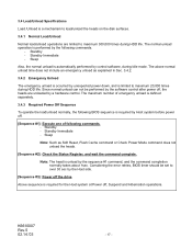
... Sleep Note: Such as explained in Sec. 3.4.2. 3.4.2 Emergency Unload The emergency unload is occurred by the Host side. [Sequence #3]: Power off the drive Above sequence is required for the Host system at Power off . [Sequence #1]: Execute one of emergency unload is defined separately. 3.4.3 Required Power Off ...02.14.'03 - 17 - Since normal unload can not be set to over 30 sec by unexpected power down, and is limited to maximum 20,000 times during HDD life. 3.4 Load/Unload Specifications Load /Unload is a mechanism to load/unload the heads on the disk surfaces. 3.4.1 Normal...
... Sleep Note: Such as explained in Sec. 3.4.2. 3.4.2 Emergency Unload The emergency unload is occurred by the Host side. [Sequence #3]: Power off the drive Above sequence is required for the Host system at Power off . [Sequence #1]: Execute one of emergency unload is defined separately. 3.4.3 Required Power Off ...02.14.'03 - 17 - Since normal unload can not be set to over 30 sec by unexpected power down, and is limited to maximum 20,000 times during HDD life. 3.4 Load/Unload Specifications Load /Unload is a mechanism to load/unload the heads on the disk surfaces. 3.4.1 Normal...
Owners Manual
Page 18
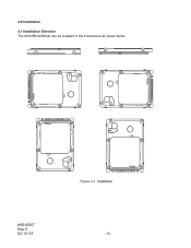
4.0 Installation 4.1 Installation Direction The DK23FB-60/40/20 can be installed in the 6 directions as shown below. K6610007 Rev.5 02.14.'03 Figure 4-1 Installation - 18 -
4.0 Installation 4.1 Installation Direction The DK23FB-60/40/20 can be installed in the 6 directions as shown below. K6610007 Rev.5 02.14.'03 Figure 4-1 Installation - 18 -
Owners Manual
Page 20
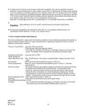
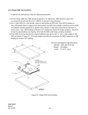
... the HDD movement or HDD floating by the required holding torque above item 1), put a body weight on then soft sponge sheet or slippery hard desk surface, the HDD has unstable conditions such as HDD self-vibration at HDD test. It may cause the similar symptom. The HDD should... by tension of I =7.3X10⁻⁴ kg m2 ) HDD X Axis Direction K6610007 Rev.5 02.14.'03 ABS-sheet (t = 5mm) Figure 4-3 Single HDD Test Condition - 20 - The body weight is placed on the HDD as specified below. 4.2.2 Single HDD Test Condition To optimize the performance, keep the following instructions. 1) For the...
... the HDD movement or HDD floating by the required holding torque above item 1), put a body weight on then soft sponge sheet or slippery hard desk surface, the HDD has unstable conditions such as HDD self-vibration at HDD test. It may cause the similar symptom. The HDD should... by tension of I =7.3X10⁻⁴ kg m2 ) HDD X Axis Direction K6610007 Rev.5 02.14.'03 ABS-sheet (t = 5mm) Figure 4-3 Single HDD Test Condition - 20 - The body weight is placed on the HDD as specified below. 4.2.2 Single HDD Test Condition To optimize the performance, keep the following instructions. 1) For the...
Owners Manual
Page 22
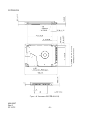
full thread 100±0.45 3.99±0.25 K6610007 Rev.5 02.14.'03 2 42 (Unit : mm) Figure 4-4 Dimensions (DK23FB-60/40/20) - 22 - 3±0.25 4.07±0.25 10.14±0.375 69.85±0.25 Drive width at mounting (70.1 Maximum drive width) 9.5 ± 0.2 2 4.4 Dimensions 4-M3 3.5mm min. full thread 76.6 ± 0.25 14.0 ± 0.25 10.24 ± 0.25 61.72±0.25 4-M3 3.0mm min.
full thread 100±0.45 3.99±0.25 K6610007 Rev.5 02.14.'03 2 42 (Unit : mm) Figure 4-4 Dimensions (DK23FB-60/40/20) - 22 - 3±0.25 4.07±0.25 10.14±0.375 69.85±0.25 Drive width at mounting (70.1 Maximum drive width) 9.5 ± 0.2 2 4.4 Dimensions 4-M3 3.5mm min. full thread 76.6 ± 0.25 14.0 ± 0.25 10.24 ± 0.25 61.72±0.25 4-M3 3.0mm min.
Owners Manual
Page 26
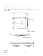
Blocking receptacles Pos.20 of the HDD.) 3.86 mm 2 mm PIN1 PINS REMOVED(KEY) 2 mm K6610007 Rev.5 02.14.'03 PIN44 PIN20 REMOVED(KEY) Figure 6-3 Connector Location Table 6.1 Recommended socket connector Drive interface connector IRISO : 9282B-47Z02-GF or DDK : KKS-PF50A-R33 or equivalent Recommended socket connector IRISO : IMSA-9289S-44A-GF...
Blocking receptacles Pos.20 of the HDD.) 3.86 mm 2 mm PIN1 PINS REMOVED(KEY) 2 mm K6610007 Rev.5 02.14.'03 PIN44 PIN20 REMOVED(KEY) Figure 6-3 Connector Location Table 6.1 Recommended socket connector Drive interface connector IRISO : 9282B-47Z02-GF or DDK : KKS-PF50A-R33 or equivalent Recommended socket connector IRISO : IMSA-9289S-44A-GF...
Owners Manual
Page 27
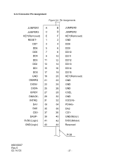
...- 39 5VDC(Logic) 41 GND(Logic) 43 B JUMPER0 D JUMPER2 F KEY(Removed) 2 GND 4 DD8 6 DD9 8 DD10 10 DD11 12 DD12 14 DD13 16 DD14 18 DD15 20 KEY(Removed) 22 GND 24 GND 26 GND 28 CSEL 30 GND 32 IOCS16- 34 PDIAG- 36 DA2 38 CS1- 40 GND(Motor) 42 5VDC...
...- 39 5VDC(Logic) 41 GND(Logic) 43 B JUMPER0 D JUMPER2 F KEY(Removed) 2 GND 4 DD8 6 DD9 8 DD10 10 DD11 12 DD12 14 DD13 16 DD14 18 DD15 20 KEY(Removed) 22 GND 24 GND 26 GND 28 CSEL 30 GND 32 IOCS16- 34 PDIAG- 36 DA2 38 CS1- 40 GND(Motor) 42 5VDC...
Owners Manual
Page 30
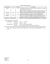
The host in the host system. See Sec. 4.3 " Drive Address Setting (Drive 0/Drive 1)" for DMA data transfers between host and device, when it may cause factional degradations or some errors. The device shall assert this signal, used for .... DMARQ DMACKJUMPER0,1,2 Pin 39 21 29 PIN-A,B,D I/O type I/O O I /F cable should be no longer than 50cm(20 inches) including the circuit pattern length in response to DMARQ to either acknowledge that data has been accepted, or that Drive 1 is present when the power is ready to transfer data. Upon receipt of a command from...
The host in the host system. See Sec. 4.3 " Drive Address Setting (Drive 0/Drive 1)" for DMA data transfers between host and device, when it may cause factional degradations or some errors. The device shall assert this signal, used for .... DMARQ DMACKJUMPER0,1,2 Pin 39 21 29 PIN-A,B,D I/O type I/O O I /F cable should be no longer than 50cm(20 inches) including the circuit pattern length in response to DMARQ to either acknowledge that data has been accepted, or that Drive 1 is present when the power is ready to transfer data. Upon receipt of a command from...
Owners Manual
Page 38
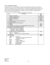
... 3 Number of logical heads 4 - 5 Retired 6 Number of logical sectors per logical track 7-9 Vendor specific 10-19 Serial number (20 ASCII characters) 20 Retired 21 Retired 22 Number of ECC bytes passed on READ/WRITE LONG commands 23-26 Firmware revision(8 ASCII Characters) 27-46 Model number...(40 ASCII Characters) DK23FB-60: "HITACHI_DK23FB-60" DK23FB-40: "HITACHI_DK23FB-40" DK23FB-20: "HITACHI_DK23FB-20" 47 Number of sectors on multiple commands Bit 15 - 8 80h (fixed) Bit 7 - 0 Number of sectors on multiple command 48 ...
... 3 Number of logical heads 4 - 5 Retired 6 Number of logical sectors per logical track 7-9 Vendor specific 10-19 Serial number (20 ASCII characters) 20 Retired 21 Retired 22 Number of ECC bytes passed on READ/WRITE LONG commands 23-26 Firmware revision(8 ASCII Characters) 27-46 Model number...(40 ASCII Characters) DK23FB-60: "HITACHI_DK23FB-60" DK23FB-40: "HITACHI_DK23FB-40" DK23FB-20: "HITACHI_DK23FB-20" 47 Number of sectors on multiple commands Bit 15 - 8 80h (fixed) Bit 7 - 0 Number of sectors on multiple command 48 ...
Owners Manual
Page 44
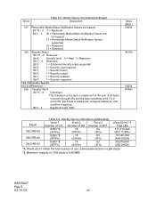
... 160-254 Reserved 255 Integrity Word Bit 15 - 8 Checksum. Bit 7 - 0 Signature Code "A5h" Value (HEX.) 0000h 0XXXh 0000h XXA5h Model DK23FB-60 DK23FB-40 DK23FB-20 Table 6.6 Identify Device information (Addressing) Word 1 Word 2 Word 3 Number of user addressable sectors in word 255. The checksum is the two's complement of the sum...
... 160-254 Reserved 255 Integrity Word Bit 15 - 8 Checksum. Bit 7 - 0 Signature Code "A5h" Value (HEX.) 0000h 0XXXh 0000h XXA5h Model DK23FB-60 DK23FB-40 DK23FB-20 Table 6.6 Identify Device information (Addressing) Word 1 Word 2 Word 3 Number of user addressable sectors in word 255. The checksum is the two's complement of the sum...
Owners Manual
Page 54
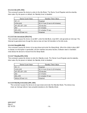
By the power on default, the Standby timer is disabled. Sector Count Value SC = 0 0 6.3.2.6.4 Idle [97h, E3h] This command causes the device to enter to the Idle Mode. The Sector Count Register sets the standby timer value.
By the power on default, the Standby timer is disabled. Sector Count Value SC = 0 0 6.3.2.6.4 Idle [97h, E3h] This command causes the device to enter to the Idle Mode. The Sector Count Register sets the standby timer value.
Owners Manual
Page 77
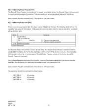
... Bit 0 Identifier 1-16 Password(32bytes) 17-255 Reserved Contents 0 = Compare user password 1 = Compare master password The Security Erase Unit command erases all user data. DK23FB-20 : 44 minutes 28 minutes 12 minutes K6610007 Rev.5 02.14.'03 - 77 - Device returns Aborted command error if the device is in Frozen mode. 6.3.2.9.7 Security...
... Bit 0 Identifier 1-16 Password(32bytes) 17-255 Reserved Contents 0 = Compare user password 1 = Compare master password The Security Erase Unit command erases all user data. DK23FB-20 : 44 minutes 28 minutes 12 minutes K6610007 Rev.5 02.14.'03 - 77 - Device returns Aborted command error if the device is in Frozen mode. 6.3.2.9.7 Security...
Owners Manual
Page 85
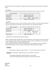
... changed by Initial Device Parameter command, the Identify Device Word 54 Number of Identify device command data word 1 is not used for DK23FB-60/40/20. CHS Mode Maximum sector number and maximum head number are fixed values, and the values are 16 and 63. DRV Maximum Head Maximum Sector Number...
... changed by Initial Device Parameter command, the Identify Device Word 54 Number of Identify device command data word 1 is not used for DK23FB-60/40/20. CHS Mode Maximum sector number and maximum head number are fixed values, and the values are 16 and 63. DRV Maximum Head Maximum Sector Number...