Owners Manual
Page 5
...50 units' package) during handling or drive failure. Recorded data on the disk may be lost due to make changes from any damage. (Keep some extra packages for the drive transportation) 21. Further Hitachi... reserves the right to revise this publication and to unexpected or accidental power loss during write operation. Safety Instructions (Continued) Caution 19. Data may be lost due to accidents such as disasters, shock damage during drive... any damage. 22. Prevent humidity when the drive is correct please feel free to the contents ...
...50 units' package) during handling or drive failure. Recorded data on the disk may be lost due to make changes from any damage. (Keep some extra packages for the drive transportation) 21. Further Hitachi... reserves the right to revise this publication and to unexpected or accidental power loss during write operation. Safety Instructions (Continued) Caution 19. Data may be lost due to accidents such as disasters, shock damage during drive... any damage. 22. Prevent humidity when the drive is correct please feel free to the contents ...

Owners Manual
Page 7
..., 41h] 48 6.3.2.5.3 Recalibrate [1Xh] 48 6.3.2.5.4 Seek [7Xh] 48 6.3.2.5.5 Set Features [EFh] 48 6.3.2.5.6 Set Multiple Mode [C6h] 49 6.3.2.5.7 Execute Device Diagnostic [90h] 49 6.3.2.5.8 Flush Cache [E7h] 50 6.3.2.6 Power Commands 51 6.3.2.6.1 Power Management 51 6.3.2.6.2 Advanced Power Management 52 6.3.2.6.3 Check Power Mode [98h, E5h] 53 6.3.2.6.4 Idle [97h, E3h] 54 6.3.2.6.5 Idle Immediate [95h, E1h] 54...
..., 41h] 48 6.3.2.5.3 Recalibrate [1Xh] 48 6.3.2.5.4 Seek [7Xh] 48 6.3.2.5.5 Set Features [EFh] 48 6.3.2.5.6 Set Multiple Mode [C6h] 49 6.3.2.5.7 Execute Device Diagnostic [90h] 49 6.3.2.5.8 Flush Cache [E7h] 50 6.3.2.6 Power Commands 51 6.3.2.6.1 Power Management 51 6.3.2.6.2 Advanced Power Management 52 6.3.2.6.3 Check Power Mode [98h, E5h] 53 6.3.2.6.4 Idle [97h, E3h] 54 6.3.2.6.5 Idle Immediate [95h, E1h] 54...
Owners Manual
Page 9
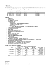
...-2 - 100 MB/sec: Ultra DMA mode-5 (Device-Buffer) - 32.9 to 50.2 MB/sec (DK23FB-60/40), 30.0 to 45.5 MB/sec (DK23FB-20) - Model DK23FB-60 DK23FB-40 DK23FB-20 Capacity (Formatted) 60.011 GB 40.007 GB 20.003 GB Height 9.5 mm 9.5 mm 9.5 mm Interface ATA-5(IDE) ATA-5(IDE) ATA-5(IDE)... [Features] - 1.0 General 1.1 Introduction The DK23FB series disk drives reach high capacities (60/40/20GB for ...
...-2 - 100 MB/sec: Ultra DMA mode-5 (Device-Buffer) - 32.9 to 50.2 MB/sec (DK23FB-60/40), 30.0 to 45.5 MB/sec (DK23FB-20) - Model DK23FB-60 DK23FB-40 DK23FB-20 Capacity (Formatted) 60.011 GB 40.007 GB 20.003 GB Height 9.5 mm 9.5 mm 9.5 mm Interface ATA-5(IDE) ATA-5(IDE) ATA-5(IDE)... [Features] - 1.0 General 1.1 Introduction The DK23FB series disk drives reach high capacities (60/40/20GB for ...

Owners Manual
Page 13
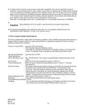
... Specification Summary 3.1 Principal Specifications Table 3.1 Principal Specifications Specifications No. Start up *5 - Item DK23FB-60 DK23FB-40 DK23FB-20 Units 1 Capacity per drive (Formatted) 60.011 40.007 20.003 GB Capacity per sector 512 Bytes Disks 2 1 Heads 4 3 2 Cylinders 42518 2 Seek time Average 13 *1 ms ... Recording method 3.35 (85.0) ME2PRML, ID-Less format Mtpm(kTPI) 5 Interface ATA-5(IDE) Data transfer rate (Disk-Buffer) 32.9 - 50.2 30.0 - 45.5 MB/sec Data transfer rate (Host-Buffer) Max. 16.6 MB/sec (PIO mode 4/ Multiword DMA mode 2) Max...
... Specification Summary 3.1 Principal Specifications Table 3.1 Principal Specifications Specifications No. Start up *5 - Item DK23FB-60 DK23FB-40 DK23FB-20 Units 1 Capacity per drive (Formatted) 60.011 40.007 20.003 GB Capacity per sector 512 Bytes Disks 2 1 Heads 4 3 2 Cylinders 42518 2 Seek time Average 13 *1 ms ... Recording method 3.35 (85.0) ME2PRML, ID-Less format Mtpm(kTPI) 5 Interface ATA-5(IDE) Data transfer rate (Disk-Buffer) 32.9 - 50.2 30.0 - 45.5 MB/sec Data transfer rate (Host-Buffer) Max. 16.6 MB/sec (PIO mode 4/ Multiword DMA mode 2) Max...
Owners Manual
Page 16
...operating rotational shock, the specification is 50K radian/sec2 or less (2 ms, half sine wave). 3.3 Drive Usage Condition Specifications The drive is stopped during power on hours (POH) : Less than 20% of the actuator with a delay time at product shipment, except during Standby and Sleep modes. ... : Max. 300,000 times. Grounding AC current (measuring between electrical ground and system frame ground without the drive. Seek rate for the drive can be less than 50 mAp-p (Frequency Range: less than 500mVp-p. The heads are defined for usage under the following conditions. Grounding...
...operating rotational shock, the specification is 50K radian/sec2 or less (2 ms, half sine wave). 3.3 Drive Usage Condition Specifications The drive is stopped during power on hours (POH) : Less than 20% of the actuator with a delay time at product shipment, except during Standby and Sleep modes. ... : Max. 300,000 times. Grounding AC current (measuring between electrical ground and system frame ground without the drive. Seek rate for the drive can be less than 50 mAp-p (Frequency Range: less than 500mVp-p. The heads are defined for usage under the following conditions. Grounding...

Owners Manual
Page 39
... Multiple sector setting Bit 15-90 = Reserved Bit 8 1 = Multiple sector setting is equal to or greater than 5 minutes. Word Table 6.5 Identify Device Information (Continued) Description 50 Capabilities Bit 15 0 (fixed) Bit 14 1 (fixed) Bit 13 - 1 0 = Reserved Bit 0 1 = Standby timer value is valid Bit 7 - 0Current setting for number of current sectors per...
... Multiple sector setting Bit 15-90 = Reserved Bit 8 1 = Multiple sector setting is equal to or greater than 5 minutes. Word Table 6.5 Identify Device Information (Continued) Description 50 Capabilities Bit 15 0 (fixed) Bit 14 1 (fixed) Bit 13 - 1 0 = Reserved Bit 0 1 = Standby timer value is valid Bit 7 - 0Current setting for number of current sectors per...

Owners Manual
Page 50
... In case of Write Fault, the command is aborted and Status Register bit 5 DWF(Device Write Fault) is 30 seconds. K6610007 Rev.5 02.14.'03 - 50 - 6.3.2.5.8 Flush Cache [E7h] The Flush Cache command is occurred. BSY is set until all write cache data are written on the disk or a write error...
... In case of Write Fault, the command is aborted and Status Register bit 5 DWF(Device Write Fault) is 30 seconds. K6610007 Rev.5 02.14.'03 - 50 - 6.3.2.5.8 Flush Cache [E7h] The Flush Cache command is occurred. BSY is set until all write cache data are written on the disk or a write error...

Owners Manual
Page 98
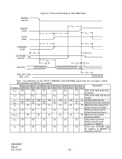
...:0) SYMBOL Description t0 Cycle Time tD DIOR- /DIOW- Pulse Width tE DIOR- Data Hold K6610007 Rev.5 02.14.'03 MIN(ns) 120 70 5 MAX(ns) 50 - 98 - Data Access tF DIOR- Figure 6-5 IORDY Timing Read Data Valid DIOR-/DIOW-
...:0) SYMBOL Description t0 Cycle Time tD DIOR- /DIOW- Pulse Width tE DIOR- Data Hold K6610007 Rev.5 02.14.'03 MIN(ns) 120 70 5 MAX(ns) 50 - 98 - Data Access tF DIOR- Figure 6-5 IORDY Timing Read Data Valid DIOR-/DIOW-
Owners Manual
Page 100
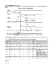
... 0 0 0 0 0 0 Maximum delay time for output drivers turning on tENV tZIORDY 20 70 20 70 20 70 20 55 20 55 20 50 Envelope time 0 0 0 0 0 0 Minimum time waiting before assertion and negation of DMACK_ K6610007 Rev.5 02.14.'03 - 100 - Note: The definitions for output drivers to -driving until DMARQ and DMACK are not in effect until the first...
... 0 0 0 0 0 0 Maximum delay time for output drivers turning on tENV tZIORDY 20 70 20 70 20 70 20 55 20 55 20 50 Envelope time 0 0 0 0 0 0 Minimum time waiting before assertion and negation of DMACK_ K6610007 Rev.5 02.14.'03 - 100 - Note: The definitions for output drivers to -driving until DMARQ and DMACK are not in effect until the first...

Owners Manual
Page 101
... MAX MIN MAX MIN MAX MIN MAX MIN MAX 112 73 54 39 25 230 153 115 86 57 15 10 7 7 5 5 5 5 5 5 70 48 31 20 6.7 6.2 6.2 6.2 6.2 6.2 14.7 9.7 6.8 6.8 4.8 4.8 4.8 4.8 4.8 4.8 72.9 50.9 33.9 22.6 9.5 9.0 9.0 9.0 9.0 9.0 Mode5(ns) MIN MAX 16.8 38 4 4.6 4.8 4.8 2.3 2.8 6.0 6.0 Description Cycle time allowing for asymmetry and clock variation Two cycle time allowing for clock variation...
... MAX MIN MAX MIN MAX MIN MAX MIN MAX 112 73 54 39 25 230 153 115 86 57 15 10 7 7 5 5 5 5 5 5 70 48 31 20 6.7 6.2 6.2 6.2 6.2 6.2 14.7 9.7 6.8 6.8 4.8 4.8 4.8 4.8 4.8 4.8 72.9 50.9 33.9 22.6 9.5 9.0 9.0 9.0 9.0 9.0 Mode5(ns) MIN MAX 16.8 38 4 4.6 4.8 4.8 2.3 2.8 6.0 6.0 Description Cycle time allowing for asymmetry and clock variation Two cycle time allowing for clock variation...

Owners Manual
Page 102
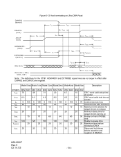
SYMBOL tRFS tRP Mode 0(ns) Mode 1(ns) Mode 2(ns) Mode3(ns) MIN MAX MIN MAX MIN MAX MIN MAX 75 70 60 60 160 125 100 100 Mode4(ns) MIN MAX 60 100 Mode5(ns) Description MIN MAX 50 Ready-to-final STROBE time 85 Ready-to request termination of the Ultra DMA burst no sooner than tRP after HDMARDYis negated. Figure 6-10 Host pausing an Ultra DMA Read DMARQ (device) DMACK(host) STOP tRP (host) HDMARDY(host) tRFS DSTROBE (device) DD(15:0) (device) Note: The host asserts STOP to -pause time K6610007 Rev.5 02.14.'03 - 102 -
SYMBOL tRFS tRP Mode 0(ns) Mode 1(ns) Mode 2(ns) Mode3(ns) MIN MAX MIN MAX MIN MAX MIN MAX 75 70 60 60 160 125 100 100 Mode4(ns) MIN MAX 60 100 Mode5(ns) Description MIN MAX 50 Ready-to-final STROBE time 85 Ready-to request termination of the Ultra DMA burst no sooner than tRP after HDMARDYis negated. Figure 6-10 Host pausing an Ultra DMA Read DMARQ (device) DMACK(host) STOP tRP (host) HDMARDY(host) tRFS DSTROBE (device) DD(15:0) (device) Note: The host asserts STOP to -pause time K6610007 Rev.5 02.14.'03 - 102 -
Owners Manual
Page 103
Note: The definitions for output drivers turning on tIORDYZ 20 20 20 20 20 20 Maximum time before assertion and negation of DMACK_ tSS 50 50 50 50 50 50 Time from STROBE edge to release tZAH 20 20 20 20 20 20 Minimum delay time for the STOP, HDMARDY and DSTROBE signal lines are no... 6.2 10 CRC word valid hold times before releasing IORDY tACK 20 20 20 20 20 20 Setup and hold time at sender tLI 0 150 0 150 0 150 0 100 0 100 0 75 Limited interlock time tMLI 20 20 20 20 20 20 Interlock time with minimum tAZ 10 10 10 10 10 10 Maximum...
Note: The definitions for output drivers turning on tIORDYZ 20 20 20 20 20 20 Maximum time before assertion and negation of DMACK_ tSS 50 50 50 50 50 50 Time from STROBE edge to release tZAH 20 20 20 20 20 20 Minimum delay time for the STOP, HDMARDY and DSTROBE signal lines are no... 6.2 10 CRC word valid hold times before releasing IORDY tACK 20 20 20 20 20 20 Setup and hold time at sender tLI 0 150 0 150 0 150 0 100 0 100 0 75 Limited interlock time tMLI 20 20 20 20 20 20 Interlock time with minimum tAZ 10 10 10 10 10 10 Maximum...
Owners Manual
Page 104
... to release tZAH 20 20 20 20 20 20 Minimum delay time for the STOP, HDMARDY and DSTROBE signal lines are no longer in effect after DMARQ and DMACK are negated. Note: The definitions for output drivers turning on tRFS 75 70 60 60 60 50 Ready-to-final-...STROBE time tRP 160 125 100 100 100 85 Ready-to-pause time tIORDYZ 20 20 20 20 20 20 Maximum time before releasing IORDY tACK 20 20 20 20 20 20 Setup and hold time at sender tCVH 6.2 6.2 6.2 6.2 6.2 10...
... to release tZAH 20 20 20 20 20 20 Minimum delay time for the STOP, HDMARDY and DSTROBE signal lines are no longer in effect after DMARQ and DMACK are negated. Note: The definitions for output drivers turning on tRFS 75 70 60 60 60 50 Ready-to-final-...STROBE time tRP 160 125 100 100 100 85 Ready-to-pause time tIORDYZ 20 20 20 20 20 20 Maximum time before releasing IORDY tACK 20 20 20 20 20 20 Setup and hold time at sender tCVH 6.2 6.2 6.2 6.2 6.2 10...

Owners Manual
Page 105
...20 70 20 70 0 0 0 tACK 20 20 20 tDZFS 70 48 31 Mode3(ns) MIN MAX 20 6.2 0 100 0 20 55 0 20 20 Mode4(ns) MIN MAX 6.7 6.2 0 100 0 20 55 0 20 6.7 Mode5(ns) Description MIN MAX 4.8 Data valid setup time at sender 4.8 Data valid hold time at sender 0 75 Limited interlock time 0 Unlimited interlock 20 50 Envelope time 0 Minimum time before driving IORDY 20... Setup and hold times before assertion and negation of DMACK_ 25 Time from data output released-to-driving until DMARQ and ...
...20 70 20 70 0 0 0 tACK 20 20 20 tDZFS 70 48 31 Mode3(ns) MIN MAX 20 6.2 0 100 0 20 55 0 20 20 Mode4(ns) MIN MAX 6.7 6.2 0 100 0 20 55 0 20 6.7 Mode5(ns) Description MIN MAX 4.8 Data valid setup time at sender 4.8 Data valid hold time at sender 0 75 Limited interlock time 0 Unlimited interlock 20 50 Envelope time 0 Minimum time before driving IORDY 20... Setup and hold times before assertion and negation of DMACK_ 25 Time from data output released-to-driving until DMARQ and ...

Owners Manual
Page 106
...tDS 15 10 7 7 5 4 Data setup time at recipient tDH 5 5 5 5 5 4.6 Data hold time at recipient tDVS 70 48 31 20 6.7 4.8 Data valid setup time at sender tDVH 6.2 6.2 6.2 6.2 6.2 4.8 Data valid hold time at the device until some time after they ...cable propagation delay shall not allow the data signals to be considered stable at sender tDSIC 14.7 9.7 6.8 6.8 4.8 tDHIC 4.8 4.8 4.8 4.8 4.8 tDVSIC 72.9 50.9 33.9 22.6 9.5 2.3 Recipient IC data setup time 2.8 Recipient IC data hold time 6.0 Sender IC data valid setup time tDVHIC 9 9 9 9 9...
...tDS 15 10 7 7 5 4 Data setup time at recipient tDH 5 5 5 5 5 4.6 Data hold time at recipient tDVS 70 48 31 20 6.7 4.8 Data valid setup time at sender tDVH 6.2 6.2 6.2 6.2 6.2 4.8 Data valid hold time at the device until some time after they ...cable propagation delay shall not allow the data signals to be considered stable at sender tDSIC 14.7 9.7 6.8 6.8 4.8 tDHIC 4.8 4.8 4.8 4.8 4.8 tDVSIC 72.9 50.9 33.9 22.6 9.5 2.3 Recipient IC data setup time 2.8 Recipient IC data hold time 6.0 Sender IC data valid setup time tDVHIC 9 9 9 9 9...

Owners Manual
Page 107
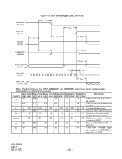
SYMBOL tRFS tRP Mode 0(ns) Mode 1(ns) Mode 2(ns) MIN MAX MIN MAX MIN MAX 75 70 60 160 125 100 Mode 3(ns) MIN MAX 60 100 Mode 4(ns) Mde5(ns) Description MIN MAX MIN MAX 60 50 Ready-to-final STROBE time 100 85 Ready-to request termination of the Ultra DMA burst no sooner than tRP after DDMARDY- DMARQ (device) DMACK- (host) STOP (host) Figure 6-15 Device pausing an Ultra DMA Write tRP DDMARDY(device) tRFS HSTROBE (host) DD(15:0) (host) Note: The device negates DMARQ to -pause time K6610007 Rev.5 02.14.'03 - 107 - is negated.
SYMBOL tRFS tRP Mode 0(ns) Mode 1(ns) Mode 2(ns) MIN MAX MIN MAX MIN MAX 75 70 60 160 125 100 Mode 3(ns) MIN MAX 60 100 Mode 4(ns) Mde5(ns) Description MIN MAX MIN MAX 60 50 Ready-to-final STROBE time 100 85 Ready-to request termination of the Ultra DMA burst no sooner than tRP after DDMARDY- DMARQ (device) DMACK- (host) STOP (host) Figure 6-15 Device pausing an Ultra DMA Write tRP DDMARDY(device) tRFS HSTROBE (host) DD(15:0) (host) Note: The device negates DMARQ to -pause time K6610007 Rev.5 02.14.'03 - 107 - is negated.
Owners Manual
Page 108
... STOP K6610007 Rev.5 02.14.'03 - 108 - tACK tCVS tCVH CRC tACK Note: The definitions for DMACK_ tSS 50 50 50 50 50 50 Time from STROBE edge to release tIORDYZ 20 20 20 20 20 20 Maximum time before releasing IORDY tACK 20 20 20 20 20 20 Setup and hold times for the STOP, DDMARDY and HSTROBE signal lines are no longer in effect after DMARQ...
... STOP K6610007 Rev.5 02.14.'03 - 108 - tACK tCVS tCVH CRC tACK Note: The definitions for DMACK_ tSS 50 50 50 50 50 50 Time from STROBE edge to release tIORDYZ 20 20 20 20 20 20 Maximum time before releasing IORDY tACK 20 20 20 20 20 20 Setup and hold times for the STOP, DDMARDY and HSTROBE signal lines are no longer in effect after DMARQ...

Owners Manual
Page 109
... time at sender tLI 0 150 0 150 0 150 0 100 0 100 0 75 Limited interlock time tMLI 20 20 20 20 20 20 Interlock time with minimum tRFS 75 70 60 60 60 50 Ready-to -pause time tIORDYZ 20 20 20 20 20 20 Maximum time before releasing IORDY tACK 20 20 20 20 20 20 Setup and hold times for the STOP, DDMARDY and HSTROBE signal lines are no longer...
... time at sender tLI 0 150 0 150 0 150 0 100 0 100 0 75 Limited interlock time tMLI 20 20 20 20 20 20 Interlock time with minimum tRFS 75 70 60 60 60 50 Ready-to -pause time tIORDYZ 20 20 20 20 20 20 Maximum time before releasing IORDY tACK 20 20 20 20 20 20 Setup and hold times for the STOP, DDMARDY and HSTROBE signal lines are no longer...

Owners Manual
Page 112
Name 1 Package box 2 HDD Cushion 3 Upper Cushion 4 Side Cushion 5 Desiccant 6 Vinyl Package Materials Card box Card Board Card Board . The following items will be based on the exterior of the factory packaging is indicated on user request. (a) HDD type (b) HDD serial number (c) Package serial number (d) Quantity K6610007 Rev.5 02.14.'03 - 112 - Card Board Silicagel ESD protective bags Quantity 1 1 1 4 50 50 (2) Standard Identification Label The label is described in this reference. (1) Packaging Components No. Factory Packaging The structure of the package.
Name 1 Package box 2 HDD Cushion 3 Upper Cushion 4 Side Cushion 5 Desiccant 6 Vinyl Package Materials Card box Card Board Card Board . The following items will be based on the exterior of the factory packaging is indicated on user request. (a) HDD type (b) HDD serial number (c) Package serial number (d) Quantity K6610007 Rev.5 02.14.'03 - 112 - Card Board Silicagel ESD protective bags Quantity 1 1 1 4 50 50 (2) Standard Identification Label The label is described in this reference. (1) Packaging Components No. Factory Packaging The structure of the package.