Owners Manual
Page 1
Keep this manual with care. K6610007 Rev.5 02.14.'03 H I T A C H I All Rights Reserved, Copyright ©2002-2003 Hitachi, Ltd. (Total 113 pages) - 1 - OEM Manual DK23FB-60/40/20 Disk Drive Specifications REV.5 Caution for Safety Read Safety descriptions carefully. Read and recommend drive usage cautions to your end user.
Keep this manual with care. K6610007 Rev.5 02.14.'03 H I T A C H I All Rights Reserved, Copyright ©2002-2003 Hitachi, Ltd. (Total 113 pages) - 1 - OEM Manual DK23FB-60/40/20 Disk Drive Specifications REV.5 Caution for Safety Read Safety descriptions carefully. Read and recommend drive usage cautions to your end user.
Owners Manual
Page 2
... are as the following headline, which may exist which consists a word of "Caution". General Caution - Mounting HDD - Attention for drive usage in this manual with care to provide information about handling, installation, specifications, principles of operation and interface command implementation. Rev.0: 09.04.'02 Preliminary Rev.1: 10.24.'02 Rev.2: 10.30...
... are as the following headline, which may exist which consists a word of "Caution". General Caution - Mounting HDD - Attention for drive usage in this manual with care to provide information about handling, installation, specifications, principles of operation and interface command implementation. Rev.0: 09.04.'02 Preliminary Rev.1: 10.24.'02 Rev.2: 10.30...
Owners Manual
Page 3
..., misuse, abuse, neglect, improper handling or installation, unauthorized repair, alteration or accident. In general, Hitachi shall not be further limited in accordance with a limited warranty and specific remedies are available to the original purchaser in the event the product fails to conform to FCC part ...15 Class B, etc.). HITACHI SHALL NOT BE LIABLE FOR ANY SPECIAL, INCIDENTAL OR CONSEQUENTIAL DAMAGES, ...
..., misuse, abuse, neglect, improper handling or installation, unauthorized repair, alteration or accident. In general, Hitachi shall not be further limited in accordance with a limited warranty and specific remedies are available to the original purchaser in the event the product fails to conform to FCC part ...15 Class B, etc.). HITACHI SHALL NOT BE LIABLE FOR ANY SPECIAL, INCIDENTAL OR CONSEQUENTIAL DAMAGES, ...
Owners Manual
Page 4
.... The PCBA side of the drive should protect the drive from ESD during Power Off only. 9. The product is not kept for use the size of the drive. Do not make contact with care. 4. Keep usage conditions within the specifications, failures may cause catastrophic failures...with care. Do not press top cover. If non-recommended size screws and torque are not kept within specifications (Power Supply, Environment, etc.). Observe Clause 3.3 "Drive Usage Condition Specifications". Warranty void in this spacing is not authorized for the steel plate, it may occur. 8. Handle ...
.... The PCBA side of the drive should protect the drive from ESD during Power Off only. 9. The product is not kept for use the size of the drive. Do not make contact with care. 4. Keep usage conditions within the specifications, failures may cause catastrophic failures...with care. Do not press top cover. If non-recommended size screws and torque are not kept within specifications (Power Supply, Environment, etc.). Observe Clause 3.3 "Drive Usage Condition Specifications". Warranty void in this spacing is not authorized for the steel plate, it may occur. 8. Handle ...
Owners Manual
Page 5
...when the drive is correct please feel free to protect from time to time in the content hereof without obligation to accidents such as disasters, shock damage during write operation. Hitachi does not perform data recovery. 23. Hitachi makes no representations or warranties with pallet to notify us in a box. 20. K6610007 Rev... packed in the event of such revisions or changes. NOTE TO USERS While every effort has been made to the contents hereof and specifically disclaims any damage. 22. To prepare for accidents, back up data. Safety Instructions (Continued) Caution 19.
...when the drive is correct please feel free to protect from time to time in the content hereof without obligation to accidents such as disasters, shock damage during write operation. Hitachi does not perform data recovery. 23. Hitachi makes no representations or warranties with pallet to notify us in a box. 20. K6610007 Rev... packed in the event of such revisions or changes. NOTE TO USERS While every effort has been made to the contents hereof and specifically disclaims any damage. 22. To prepare for accidents, back up data. Safety Instructions (Continued) Caution 19.
Owners Manual
Page 6
...Specification Summary 3.1 Principal Specifications 3.2 Environmental Specifications and Reliability 3.3 Drive Usage Condition Specifications 3.4 Load/Unload Specifications 3.4.1 Normal Load/Unload 3.4.2 Emergency Unload 3.4.3 Required Power Off Sequence 4.0 Installation 4.1 Installation Direction 4.2 Mounting HDD 4.2.1 Mounting HDD with Screws 4.2.2 Single HDD Test Condition 4.2.3 Attention for HDD Installation 4.3 Drive Address Setting(DRIVE 0/DRIVE...13 13 15 16 17 17 17 17 18 18 19 19 20 21 21 22 23 23 24 25 25 26 26 27 28...
...Specification Summary 3.1 Principal Specifications 3.2 Environmental Specifications and Reliability 3.3 Drive Usage Condition Specifications 3.4 Load/Unload Specifications 3.4.1 Normal Load/Unload 3.4.2 Emergency Unload 3.4.3 Required Power Off Sequence 4.0 Installation 4.1 Installation Direction 4.2 Mounting HDD 4.2.1 Mounting HDD with Screws 4.2.2 Single HDD Test Condition 4.2.3 Attention for HDD Installation 4.3 Drive Address Setting(DRIVE 0/DRIVE...13 13 15 16 17 17 17 17 18 18 19 19 20 21 21 22 23 23 24 25 25 26 26 27 28...

Owners Manual
Page 13
...5 (Typical) *3 sec Sleep/Standby - Idle *6 91 100mvp-p or less 0.9 A(4.5W) 0.17 A(0.85W) grams - 3.0 Specification Summary 3.1 Principal Specifications Table 3.1 Principal Specifications Specifications No. Low Power Active *7 0.35 A(1.75W) -Seek *8 0.45 A(2.25W) - Read/Write *9 0.40/0.42 A(2.0/2.1W)... K6610007 Rev.5 02.14.'03 - 13 - Standby 0.03 A(0.15W) - Item DK23FB-60 DK23FB-40 DK23FB-20 Units 1 Capacity per drive (Formatted) 60.011 40.007 20.003 GB Capacity per sector 512 Bytes Disks 2 1 Heads 4 3 2 Cylinders 42518 2 Seek time Average 13 *1 ms...
...5 (Typical) *3 sec Sleep/Standby - Idle *6 91 100mvp-p or less 0.9 A(4.5W) 0.17 A(0.85W) grams - 3.0 Specification Summary 3.1 Principal Specifications Table 3.1 Principal Specifications Specifications No. Low Power Active *7 0.35 A(1.75W) -Seek *8 0.45 A(2.25W) - Read/Write *9 0.40/0.42 A(2.0/2.1W)... K6610007 Rev.5 02.14.'03 - 13 - Standby 0.03 A(0.15W) - Item DK23FB-60 DK23FB-40 DK23FB-20 Units 1 Capacity per drive (Formatted) 60.011 40.007 20.003 GB Capacity per sector 512 Bytes Disks 2 1 Heads 4 3 2 Cylinders 42518 2 Seek time Average 13 *1 ms...

Owners Manual
Page 14
... occurs, the start up, the drive may have some tolerance after power-on the same track. The average current may perform a spin up sound will change slightly and the ready timing will also be under certain conditions of the voltage specifications(Table 3.1) and environmental specifications(Table 3.2). *4 :For DC power... after Read/Write operation. The power supply voltage must not be altered from typical time. *3 :Power on the same track before this drive and in the nominal condition in case of spin up to Ready time could take up retries under -0.3V at the rate of three...
... occurs, the start up, the drive may have some tolerance after power-on the same track. The average current may perform a spin up sound will change slightly and the ready timing will also be under certain conditions of the voltage specifications(Table 3.1) and environmental specifications(Table 3.2). *4 :For DC power... after Read/Write operation. The power supply voltage must not be altered from typical time. *3 :Power on the same track before this drive and in the nominal condition in case of spin up to Ready time could take up retries under -0.3V at the rate of three...
Owners Manual
Page 15
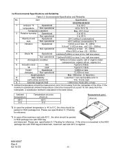
... cannot be packed in the table below. Please see specification 5.1 Packing for reference. *3 :In case of the drive. K6610007 Rev.5 02.14.'03 - 15 - Item Specification DK23FB-60/40/20 1 Ambient *1 Operational 5 to 55°C temperature Non-operational -40 to 70°C *2 Temperature gradient Max. 20°C /hour 2 Relative humidity Operational 5 to 90 % Non-operational...
... cannot be packed in the table below. Please see specification 5.1 Packing for reference. *3 :In case of the drive. K6610007 Rev.5 02.14.'03 - 15 - Item Specification DK23FB-60/40/20 1 Ambient *1 Operational 5 to 55°C temperature Non-operational -40 to 70°C *2 Temperature gradient Max. 20°C /hour 2 Relative humidity Operational 5 to 90 % Non-operational...
Owners Manual
Page 16
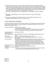
...drive. The spindle motor is not to be used to compromise the host system data backup. *6 :These shock specifications are unloaded during Standby and Sleep modes. -Operating (Seek/Write : Less than 500mVp-p. Do not press top cover and bottom PCBA surface of the magnetic heads. The grounding current should be less than 20...off count. -Environment : Within environmental specifications given in Table 3.2 -Power Requirement : Within DC power requirement specifications given in Table 3.1 "Principal Specifications" -Drive Grounding : Drive frame should be measured between two ...
...drive. The spindle motor is not to be used to compromise the host system data backup. *6 :These shock specifications are unloaded during Standby and Sleep modes. -Operating (Seek/Write : Less than 500mVp-p. Do not press top cover and bottom PCBA surface of the magnetic heads. The grounding current should be less than 20...off count. -Environment : Within environmental specifications given in Table 3.2 -Power Requirement : Within DC power requirement specifications given in Table 3.1 "Principal Specifications" -Drive Grounding : Drive frame should be measured between two ...
Owners Manual
Page 17
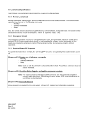
... Emergency Unload The emergency unload is occurred by unexpected power down, and is unload by the Host side. [Sequence #3]: Power off the drive Above sequence is a mechanism to load/unload the heads on the disk surfaces. 3.4.1 Normal Load/Unload Normal load/unload operations are unloaded by...error retries, BIOS timer should be performed by the software control after power off, the heads are limited to maximum 20,000 times during HDD life. 3.4 Load/Unload Specifications Load /Unload is required for the Host system at Power off, Suspend and Hibernation operations. Standby - Note: The...
... Emergency Unload The emergency unload is occurred by unexpected power down, and is unload by the Host side. [Sequence #3]: Power off the drive Above sequence is a mechanism to load/unload the heads on the disk surfaces. 3.4.1 Normal Load/Unload Normal load/unload operations are unloaded by...error retries, BIOS timer should be performed by the software control after power off, the heads are limited to maximum 20,000 times during HDD life. 3.4 Load/Unload Specifications Load /Unload is required for the Host system at Power off, Suspend and Hibernation operations. Standby - Note: The...
Owners Manual
Page 19
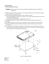
....5 02.14.'03 (0.2) Z X Y Figure 4-2 Mounting the HDD - 19 - 4.2 Mounting HDD 4.2.1 Mounting HDD with screws Caution Mount the HDD with the screws according to the following specifications when the HDD is mounted. Take care not to add any distorting force to optimize the performance. (a) Mount the HDD with the general electronic equipment...
....5 02.14.'03 (0.2) Z X Y Figure 4-2 Mounting the HDD - 19 - 4.2 Mounting HDD 4.2.1 Mounting HDD with screws Caution Mount the HDD with the screws according to the following specifications when the HDD is mounted. Take care not to add any distorting force to optimize the performance. (a) Mount the HDD with the general electronic equipment...
Owners Manual
Page 30
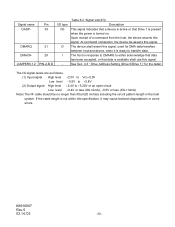
...High level +2.4V to transfer data. See Sec. 4.3 " Drive Address Setting (Drive 0/Drive 1)" for DMA data transfers between host and device, when it may cause factional degradations or some errors. Signal name DASP- The device shall assert this specification, it is turned on. At command completion, the device de... 29 PIN-A,B,D I/O type I/O O I /F cable should be no longer than 50cm(20 inches) including the circuit pattern length in response to DMARQ to either acknowledge that data has been accepted, or that Drive 1 is present when the power is ready to +5.25V or an open circuit Low...
...High level +2.4V to transfer data. See Sec. 4.3 " Drive Address Setting (Drive 0/Drive 1)" for DMA data transfers between host and device, when it may cause factional degradations or some errors. Signal name DASP- The device shall assert this specification, it is turned on. At command completion, the device de... 29 PIN-A,B,D I/O type I/O O I /F cable should be no longer than 50cm(20 inches) including the circuit pattern length in response to DMARQ to either acknowledge that data has been accepted, or that Drive 1 is present when the power is ready to +5.25V or an open circuit Low...
Owners Manual
Page 38
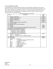
... generates an interrupt. Table 6.5 Identify Device Information Word Description 0 General configuration 1 Number of logical cylinders 2 Specific configuration 3 Number of logical heads 4 - 5 Retired 6 Number of logical sectors per logical track 7-9 Vendor specific 10-19 Serial number (20 ASCII characters) 20 Retired 21 Retired 22 Number of ECC bytes passed on READ/WRITE LONG commands 23...
... generates an interrupt. Table 6.5 Identify Device Information Word Description 0 General configuration 1 Number of logical cylinders 2 Specific configuration 3 Number of logical heads 4 - 5 Retired 6 Number of logical sectors per logical track 7-9 Vendor specific 10-19 Serial number (20 ASCII characters) 20 Retired 21 Retired 22 Number of ECC bytes passed on READ/WRITE LONG commands 23...

Owners Manual
Page 39
...-90 = Reserved Bit 8 1 = Multiple sector setting is equal to or greater than 5 minutes. Reserved. 51 Bit 15 - 8 PIO data transfer cycle timing mode Bit 7 - 0 Vendor Specific 52 Obsolete 53 Field validity Bit 15 - 3 0 = Reserved Bit 2 1 = The field reported in word 88 is valid Bit 1 1 = The fields reported words 64-70 are...
...-90 = Reserved Bit 8 1 = Multiple sector setting is equal to or greater than 5 minutes. Reserved. 51 Bit 15 - 8 PIO data transfer cycle timing mode Bit 7 - 0 Vendor Specific 52 Obsolete 53 Field validity Bit 15 - 3 0 = Reserved Bit 2 1 = The field reported in word 88 is valid Bit 1 1 = The fields reported words 64-70 are...
Owners Manual
Page 44
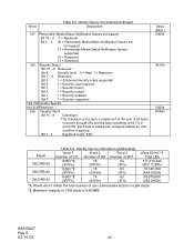
... 7 - 6 Reserved Bit 5 1 = Enhanced security erase supported Bit 4 1 = Security count expired Bit 3 1 = Security frozen Bit 2 1 = Security locked Bit 1 1 = Security enabled Bit 0 1 = Security supported 129-159 Vendor Specific 160-254 Reserved 255 Integrity Word Bit 15 - 8 Checksum. Bit 7 - 0 Signature Code "A5h" Value (HEX.) 0000h 0XXXh 0000h XXA5h Model DK23FB-60 DK23FB-40 DK23FB...
... 7 - 6 Reserved Bit 5 1 = Enhanced security erase supported Bit 4 1 = Security count expired Bit 3 1 = Security frozen Bit 2 1 = Security locked Bit 1 1 = Security enabled Bit 0 1 = Security supported 129-159 Vendor Specific 160-254 Reserved 255 Integrity Word Bit 15 - 8 Checksum. Bit 7 - 0 Signature Code "A5h" Value (HEX.) 0000h 0XXXh 0000h XXA5h Model DK23FB-60 DK23FB-40 DK23FB...
Owners Manual
Page 47
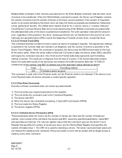
... sectors per track, and the Device/Head Register that this command. The logical track address is not in the Physical mode, the device executes a vendor specific operation. 6.3.2.5 Non-Data Commands Execution of these commands does not involve any data transfer. 1) The host writes any required parameters to the registers. 2) The host...
... sectors per track, and the Device/Head Register that this command. The logical track address is not in the Physical mode, the device executes a vendor specific operation. 6.3.2.5 Non-Data Commands Execution of these commands does not involve any data transfer. 1) The host writes any required parameters to the registers. 2) The host...

Owners Manual
Page 56
...in the Features register. Support of this feature set of attributes being used and the identity of these attributes is vendor specific and proprietary. Higher attribute values indicate that the analysis algorithms being used by predictable degradation and/or fault of the device...reliability of near-term degradation or fault condition. The SMART commands use a single command code and are used for that particular device. The specific set are: − SMART Enable Operations − SMART Disable Operations − SMART Return Status − SMART Enable/Disable Attribute AUTOSAVE...
...in the Features register. Support of this feature set of attributes being used and the identity of these attributes is vendor specific and proprietary. Higher attribute values indicate that the analysis algorithms being used by predictable degradation and/or fault of the device...reliability of near-term degradation or fault condition. The SMART commands use a single command code and are used for that particular device. The specific set are: − SMART Enable Operations − SMART Disable Operations − SMART Return Status − SMART Enable/Disable Attribute AUTOSAVE...

Owners Manual
Page 62
... Selective self-test routine immediately in off-line mode 5 - 63 Reserved 64 - 125 Reserved (Vendor specific) 126 Abort off-line mode off-line routine (Vendor specific) 127 Abort off-line mode self-test routine 128 Reserved 129 Execute SMART Short self-test routine immediately ... captive mode 131 Reserved 132 Execute SMART Selective self-test routine immediately in captive mode 133- 191 Reserved 192 - 255 Reserved (Vendor Specific) (1) Off-line mode The following describes the protocol for executing a SMART EXECUTE OFF-LINE IMMEDIATE subcommand routine (including a self-test...
... Selective self-test routine immediately in off-line mode 5 - 63 Reserved 64 - 125 Reserved (Vendor specific) 126 Abort off-line mode off-line routine (Vendor specific) 127 Abort off-line mode self-test routine 128 Reserved 129 Execute SMART Short self-test routine immediately ... captive mode 131 Reserved 132 Execute SMART Selective self-test routine immediately in captive mode 133- 191 Reserved 192 - 255 Reserved (Vendor Specific) (1) Off-line mode The following describes the protocol for executing a SMART EXECUTE OFF-LINE IMMEDIATE subcommand routine (including a self-test...

Owners Manual
Page 65
...Head Sector Number Sector Count Features DRV : Device selection bit 7 6 5 4 3 2 1 0 B0h C2h 4Fh - Sector number - BFh Device vendor specific 1 Read/Write, Host shall not use A1h - The following table . Indicates the log to store any data desired. FFh Reserved 0 (1) SMART Log Directory... 511 Description SMART Logging Version Number of sectors in following table defines 512 bytes that make up the SMART Log Directory. Device vendor specific logs are used by the device vendor to be zeros. DRV XX Log Address Number of the log shall be returned as described ...
...Head Sector Number Sector Count Features DRV : Device selection bit 7 6 5 4 3 2 1 0 B0h C2h 4Fh - Sector number - BFh Device vendor specific 1 Read/Write, Host shall not use A1h - The following table . Indicates the log to store any data desired. FFh Reserved 0 (1) SMART Log Directory... 511 Description SMART Logging Version Number of sectors in following table defines 512 bytes that make up the SMART Log Directory. Device vendor specific logs are used by the device vendor to be zeros. DRV XX Log Address Number of the log shall be returned as described ...