Owners Manual
Page 2
..., specifications, principles of yourself. Power Supply Requirements - Keep this manual were thoroughly considered, but also be careful for the safety of operation and interface command implementation. Not only follow these instructions and cautions may cause injury, fire and product damage. The indication and meaning are as the following headline..." (Page 4) and "1.2 General Caution" (Page 10 and 11) before Product Use) - Maximum Power off Interval - To use the product, read the caution for drive usage in this product safely This manual is for HDD Installation -
..., specifications, principles of yourself. Power Supply Requirements - Keep this manual were thoroughly considered, but also be careful for the safety of operation and interface command implementation. Not only follow these instructions and cautions may cause injury, fire and product damage. The indication and meaning are as the following headline..." (Page 4) and "1.2 General Caution" (Page 10 and 11) before Product Use) - Maximum Power off Interval - To use the product, read the caution for drive usage in this product safely This manual is for HDD Installation -
Owners Manual
Page 3
... Third Edition dated July 28, 1995 - In general, Hitachi shall not be responsible for product damages caused by anyone else. Please see your sales contract for loss of resident areas, such as an interface cable, is sold with a limited warranty and specific remedies...neglect, improper handling or installation, unauthorized repair, alteration or accident. EN60950 A11: 1992 Warranty and Limited Liability This product is excluded. HITACHI SHALL NOT BE LIABLE FOR ANY SPECIAL, INCIDENTAL OR CONSEQUENTIAL DAMAGES, EVEN IF INFORMED OF THE POSSIBILITY THEREOF IN ADVANCE. K6610007 Rev...
... Third Edition dated July 28, 1995 - In general, Hitachi shall not be responsible for product damages caused by anyone else. Please see your sales contract for loss of resident areas, such as an interface cable, is sold with a limited warranty and specific remedies...neglect, improper handling or installation, unauthorized repair, alteration or accident. EN60950 A11: 1992 Warranty and Limited Liability This product is excluded. HITACHI SHALL NOT BE LIABLE FOR ANY SPECIAL, INCIDENTAL OR CONSEQUENTIAL DAMAGES, EVEN IF INFORMED OF THE POSSIBILITY THEREOF IN ADVANCE. K6610007 Rev...
Owners Manual
Page 4
...3. Do not press top cover. Warranty void in case of the live metal, failures may cause catastrophic failures. Handle with the interface connector pins. Also, pins or HDA corners may cause catastrophic failures. If the hole was covered. 6. Warranty void if the ... Power Off only. 9. Observe Clause 3.3 "Drive Usage Condition Specifications". If non-recommended size screws and torque are not kept within specifications (Power Supply, Environment, etc.). K6610007 Rev.5 02.14.'03 - 4 - Do not hit the interface connector pins against other applications that pose a significant...
...3. Do not press top cover. Warranty void in case of the live metal, failures may cause catastrophic failures. Handle with the interface connector pins. Also, pins or HDA corners may cause catastrophic failures. If the hole was covered. 6. Warranty void if the ... Power Off only. 9. Observe Clause 3.3 "Drive Usage Condition Specifications". If non-recommended size screws and torque are not kept within specifications (Power Supply, Environment, etc.). K6610007 Rev.5 02.14.'03 - 4 - Do not hit the interface connector pins against other applications that pose a significant...
Owners Manual
Page 6
... 4.1 Installation Direction 4.2 Mounting HDD 4.2.1 Mounting HDD with Screws 4.2.2 Single HDD Test Condition 4.2.3 Attention for HDD Installation 4.3 Drive Address Setting(DRIVE 0/DRIVE 1) 4.4 Dimensions 5.0 Packing and Handling 5.1 Packing 5.2 Handling 6.0 Interface 6.1 Power Interface 6.2 Physical Interface 6.2.1 Connector 6.2.2 Connector Pin Assignment 6.2.3 Description of the Interface Signals 6.3 Logical Interface 6.3.1 I/O Registers 6.3.1.1 Data Register 6.3.1.2 Error Register 6.3.1.3 Features Register 6.3.1.4 Sector Count Register 6.3.1.5 Sector Number Register 6.3.1.6 Cylinder Low...
... 4.1 Installation Direction 4.2 Mounting HDD 4.2.1 Mounting HDD with Screws 4.2.2 Single HDD Test Condition 4.2.3 Attention for HDD Installation 4.3 Drive Address Setting(DRIVE 0/DRIVE 1) 4.4 Dimensions 5.0 Packing and Handling 5.1 Packing 5.2 Handling 6.0 Interface 6.1 Power Interface 6.2 Physical Interface 6.2.1 Connector 6.2.2 Connector Pin Assignment 6.2.3 Description of the Interface Signals 6.3 Logical Interface 6.3.1 I/O Registers 6.3.1.1 Data Register 6.3.1.2 Error Register 6.3.1.3 Features Register 6.3.1.4 Sector Count Register 6.3.1.5 Sector Number Register 6.3.1.6 Cylinder Low...

Owners Manual
Page 8
... 6.3.2.11.3 Device Configuration Identify [B1h, Sub 02h] 90 6.3.2.11.4 Device Configuration Set [B1h, Sub 03h] 92 6.3.2.12 Note for Write Cache and Auto Reallocation 96 6.4 Interface Signal Timing 97 6.4.1 Data Transfer Timing 97 6.4.2 Ultra DMA Data Transfer Timing 100 6.4.3 Power On and Hardware Reset Timing 110 < Glossary > 111 < Reference > 112 K6610007...
... 6.3.2.11.3 Device Configuration Identify [B1h, Sub 02h] 90 6.3.2.11.4 Device Configuration Set [B1h, Sub 03h] 92 6.3.2.12 Note for Write Cache and Auto Reallocation 96 6.4 Interface Signal Timing 97 6.4.1 Data Transfer Timing 97 6.4.2 Ultra DMA Data Transfer Timing 100 6.4.3 Power On and Hardware Reset Timing 110 < Glossary > 111 < Reference > 112 K6610007...
Owners Manual
Page 9
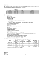
...Form Factor(9.5mm height) [Identify Device Information for 9.5mm height) in CHS mode is 8,455MB. 1.0 General 1.1 Introduction The DK23FB series disk drives reach high capacities (60/40/20GB for Setup] Table 1.1 Identify Device information (Addressing) Model Word 1 Word 3 Word 6 Number of SPT ..., half-sine wave) - SMART - Average Access Time 13 ms - Model DK23FB-60 DK23FB-40 DK23FB-20 Capacity (Formatted) 60.011 GB 40.007 GB 20.003 GB Height 9.5 mm 9.5 mm 9.5 mm Interface ATA-5(IDE) ATA-5(IDE) ATA-5(IDE) [Features] - Advanced Power Management(APM) - Maximum capacity in ...
...Form Factor(9.5mm height) [Identify Device Information for 9.5mm height) in CHS mode is 8,455MB. 1.0 General 1.1 Introduction The DK23FB series disk drives reach high capacities (60/40/20GB for Setup] Table 1.1 Identify Device information (Addressing) Model Word 1 Word 3 Word 6 Number of SPT ..., half-sine wave) - SMART - Average Access Time 13 ms - Model DK23FB-60 DK23FB-40 DK23FB-20 Capacity (Formatted) 60.011 GB 40.007 GB 20.003 GB Height 9.5 mm 9.5 mm 9.5 mm Interface ATA-5(IDE) ATA-5(IDE) ATA-5(IDE) [Features] - Advanced Power Management(APM) - Maximum capacity in ...

Owners Manual
Page 13
... -Seek *8 0.45 A(2.25W) - Item DK23FB-60 DK23FB-40 DK23FB-20 Units 1 Capacity per drive (Formatted) 60.011 40.007 20.003 GB Capacity per sector 512 Bytes Disks 2 1 Heads 4 3 2 Cylinders ...42518 2 Seek time Average 13 *1 ms (Nominal Maximum 24 *1 ms value) Minimum 3 ms 3 Average latency 5.6 ms Disk rotational speed 5,400 RPM 4 Recording density (Max.) 27.6 (702) 25.1 (639) Mbpm(kBPI) Track density Recording method 3.35 (85.0) ME2PRML, ID-Less format Mtpm(kTPI) 5 Interface...
... -Seek *8 0.45 A(2.25W) - Item DK23FB-60 DK23FB-40 DK23FB-20 Units 1 Capacity per drive (Formatted) 60.011 40.007 20.003 GB Capacity per sector 512 Bytes Disks 2 1 Heads 4 3 2 Cylinders ...42518 2 Seek time Average 13 *1 ms (Nominal Maximum 24 *1 ms value) Minimum 3 ms 3 Average latency 5.6 ms Disk rotational speed 5,400 RPM 4 Recording density (Max.) 27.6 (702) 25.1 (639) Mbpm(kBPI) Track density Recording method 3.35 (85.0) ME2PRML, ID-Less format Mtpm(kTPI) 5 Interface...
Owners Manual
Page 16
...-Power Requirement : Within DC power requirement specifications given in Table 3.2 -Mounting : Mount with recommended screws and regular torque. -Physical/Electrical Interface: ATA-5 -Handling : Do not add Electrical Static Discharge, and Vibration and Shock to system ground with a delay time at loading and... except during power on hours (POH) : Less than 20% of the magnetic heads. Grounding AC current (measuring between electrical ground and system frame ground without the drive. Also, the clicking noise of the drive. This number includes Standby, Sleep and power-on usage ...
...-Power Requirement : Within DC power requirement specifications given in Table 3.2 -Mounting : Mount with recommended screws and regular torque. -Physical/Electrical Interface: ATA-5 -Handling : Do not add Electrical Static Discharge, and Vibration and Shock to system ground with a delay time at loading and... except during power on hours (POH) : Less than 20% of the magnetic heads. Grounding AC current (measuring between electrical ground and system frame ground without the drive. Also, the clicking noise of the drive. This number includes Standby, Sleep and power-on usage ...
Owners Manual
Page 21
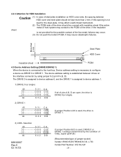
It may contact to the PCBA of the drive. If the insulation is not provided for HDD Installation Caution (1) In case of steel plate installation on the interface connector by the condition of CSEL signal (pin# 28). (Recommended type of jumper socket) Vender: IRISO ELECTRONICS CO., LTD. ...Vender Part Number: 9721HJ-GF - 21 - More than 2 mm. The device address setting is established between drives on HDD cover side, ...
It may contact to the PCBA of the drive. If the insulation is not provided for HDD Installation Caution (1) In case of steel plate installation on the interface connector by the condition of CSEL signal (pin# 28). (Recommended type of jumper socket) Vender: IRISO ELECTRONICS CO., LTD. ...Vender Part Number: 9721HJ-GF - 21 - More than 2 mm. The device address setting is established between drives on HDD cover side, ...

Owners Manual
Page 25
Typical Spin-up Current Transition 1.6 Current of +5V power 1.4 (A) 1.2 1.0 0.8 0.6 0.4 0.2 0.0 0 1 2 3 4 5 6 7 Time (sec) Figure 6-1 Power Current Transition Typical Spin-up Current Transition with Retry Retry 1.6 Current of +5V power 1.4 (A) 1.2 1.0 0.8 0.6 0.4 0.2 0.0 0 1 2 3 4 5 6 7 8 9 10 11 12 13 14 Time (sec) Figure 6-2 Power Current Transition with retries K6610007 Rev.5 02.14.'03 - 25 - Figures 6-1 and 6-2 show power current transitions after turning on the power. 6.0 Interface 6.1 Power Interface Only +5VDC power is applied to this Device.
Typical Spin-up Current Transition 1.6 Current of +5V power 1.4 (A) 1.2 1.0 0.8 0.6 0.4 0.2 0.0 0 1 2 3 4 5 6 7 Time (sec) Figure 6-1 Power Current Transition Typical Spin-up Current Transition with Retry Retry 1.6 Current of +5V power 1.4 (A) 1.2 1.0 0.8 0.6 0.4 0.2 0.0 0 1 2 3 4 5 6 7 8 9 10 11 12 13 14 Time (sec) Figure 6-2 Power Current Transition with retries K6610007 Rev.5 02.14.'03 - 25 - Figures 6-1 and 6-2 show power current transitions after turning on the power. 6.0 Interface 6.1 Power Interface Only +5VDC power is applied to this Device.
Owners Manual
Page 26
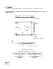
... This device has a 2mm pitch interface connector which contains a power line. The connector location is possible that the wrong insertion will cause damage to prevent wrong insertion. (It is shown in Figure 6-3. Blocking receptacles Pos.20 of socket connector is recommended to pin of ...connector or blow out fuse of the HDD.) 3.86 mm 2 mm PIN1 PINS REMOVED(KEY) 2 mm K6610007 Rev.5 02.14.'03 PIN44 PIN20 REMOVED(KEY) Figure 6-3 Connector Location Table 6.1 Recommended socket connector Drive interface connector IRISO ...
... This device has a 2mm pitch interface connector which contains a power line. The connector location is possible that the wrong insertion will cause damage to prevent wrong insertion. (It is shown in Figure 6-3. Blocking receptacles Pos.20 of socket connector is recommended to pin of ...connector or blow out fuse of the HDD.) 3.86 mm 2 mm PIN1 PINS REMOVED(KEY) 2 mm K6610007 Rev.5 02.14.'03 PIN44 PIN20 REMOVED(KEY) Figure 6-3 Connector Location Table 6.1 Recommended socket connector Drive interface connector IRISO ...
Owners Manual
Page 28
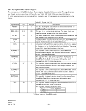
... circuit. This signal is an ATA(IDE) interface. Reserved pins should be clocked onto the host data bus. I Activating this signal, and indicates that the host is ready to configure a device as either DRIVE 0 or DRIVE1 when CSEL mode is a 16-bit bi-directional data bus... DMA burst. This signal is Write data strobe signal from the device. I /O This is selected. 6.2.3 Description of the Interface Signals The interface is pulled up inside the drive. Assertion of this signal, and indicates that the device is a flow control signal for Ultra DMA Write. CSEL GND D ...
... circuit. This signal is an ATA(IDE) interface. Reserved pins should be clocked onto the host data bus. I Activating this signal, and indicates that the host is ready to configure a device as either DRIVE 0 or DRIVE1 when CSEL mode is a 16-bit bi-directional data bus... DMA burst. This signal is Write data strobe signal from the device. I /O This is selected. 6.2.3 Description of the Interface Signals The interface is pulled up inside the drive. Assertion of this signal, and indicates that the device is a flow control signal for Ultra DMA Write. CSEL GND D ...
Owners Manual
Page 31
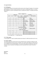
K6610007 Rev.5 02.14.'03 - 31 - 6.3 Logical Interface 6.3.1 I /O registers. Table 6.3 Register List Addresses Functions CS0- DA2 DA1 DA0 READ(DIOR-) WRITE(DIOW-) Command Block Registers 0 1 0 0 0 Data Data 0 1 0 0 1 Error Features 0 1 0 1 0 Sector Count Sector Count 0 1 0 1 1 ...
K6610007 Rev.5 02.14.'03 - 31 - 6.3 Logical Interface 6.3.1 I /O registers. Table 6.3 Register List Addresses Functions CS0- DA2 DA1 DA0 READ(DIOR-) WRITE(DIOW-) Command Block Registers 0 1 0 0 0 Data Data 0 1 0 0 1 Error Features 0 1 0 1 0 Sector Count Sector Count 0 1 0 1 1 ...
Owners Manual
Page 32
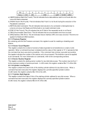
f) ICRC(Interface CRC Error): This bit indicates that an uncorrectable error has occurred. In LBA mode, this register contains Bits 7-0 of the LBA. 6.3.1.6 Cylinder Low Register This ... of the LBA. IDNF - For more information on a read or write operation. Bit 7 6 5 4 3 2 1 0 Name ICRC UNC - e) UNC(Uncorrectable Data Error): This bit indicates that an interface CRC error was occurred. In LBA mode, this register displays the currently specified cylinder number. Not Ready and Write fault) or an invalid command code...
f) ICRC(Interface CRC Error): This bit indicates that an uncorrectable error has occurred. In LBA mode, this register contains Bits 7-0 of the LBA. 6.3.1.6 Cylinder Low Register This ... of the LBA. IDNF - For more information on a read or write operation. Bit 7 6 5 4 3 2 1 0 Name ICRC UNC - e) UNC(Uncorrectable Data Error): This bit indicates that an interface CRC error was occurred. In LBA mode, this register displays the currently specified cylinder number. Not Ready and Write fault) or an invalid command code...
Owners Manual
Page 40
... Number Bit 15 - 6 Reserved for ATA-6 - 14 Bit 5 1 = Supports ATA-5 Bit 4 1 = Supports ATA-4 Bit 3 1 = Supports ATA-3 Bit 2 1 = Supports ATA-2 Bit 1 Obsolete Bit 0 Reserved 81 ATA Interface Minor Version Number 82 Command Set Supported 0000h or FFFFh = Command set notification not supported Bit 15 0 = Reserved Bit 14 1 = NOP command supported Bit 13...
... Number Bit 15 - 6 Reserved for ATA-6 - 14 Bit 5 1 = Supports ATA-5 Bit 4 1 = Supports ATA-4 Bit 3 1 = Supports ATA-3 Bit 2 1 = Supports ATA-2 Bit 1 Obsolete Bit 0 Reserved 81 ATA Interface Minor Version Number 82 Command Set Supported 0000h or FFFFh = Command set notification not supported Bit 15 0 = Reserved Bit 14 1 = NOP command supported Bit 13...
Owners Manual
Page 54
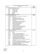
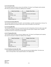
6.3.2.6.4 Idle [97h, E3h] This command causes the device to enter to the Idle Mode. Sector Count Value SC = 0 0 By the power on default, the Standby timer is disabled. The Sector Count Register sets the standby timer value.
6.3.2.6.4 Idle [97h, E3h] This command causes the device to enter to the Idle Mode. Sector Count Value SC = 0 0 By the power on default, the Standby timer is disabled. The Sector Count Register sets the standby timer value.

Owners Manual
Page 97
Setup 25 t2 DIOR-/DIOW- Recovery 25 t3 DIOW- Data Setup 20 t6 DIOR- Assertion(MAX) t8 Addr Valid To IOCS16- t3 t4 t5 t6 t6Z *1 Device Address consists of signals CS0-, CS1-, and DA2-0 *2 Data consists ...(ns) 30 40 30 K6610007 Rev.5 02.14.'03 - 97 - Data Setup 20 t4 DIOW- Data Hold 10 t5 DIOR- Data tristate t7 Addr Valid To IOCS16- 6.4 Interface Signal Timing 6.4.1 Data Transfer Timing Figures 6-4, 6-5, and 6-7 show the timing for asserting interface signals for transferring 16-bit and 8-bit data. Negation (MAX) t9 DIOR...
Setup 25 t2 DIOR-/DIOW- Recovery 25 t3 DIOW- Data Setup 20 t6 DIOR- Assertion(MAX) t8 Addr Valid To IOCS16- t3 t4 t5 t6 t6Z *1 Device Address consists of signals CS0-, CS1-, and DA2-0 *2 Data consists ...(ns) 30 40 30 K6610007 Rev.5 02.14.'03 - 97 - Data Setup 20 t4 DIOW- Data Hold 10 t5 DIOR- Data tristate t7 Addr Valid To IOCS16- 6.4 Interface Signal Timing 6.4.1 Data Transfer Timing Figures 6-4, 6-5, and 6-7 show the timing for asserting interface signals for transferring 16-bit and 8-bit data. Negation (MAX) t9 DIOR...
Owners Manual
Page 111
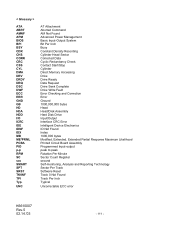
... Sector Corrected Data Cyclic Redundancy Check Contact Start/Stop Cylinder Direct Memory Accessing Drive Drive Ready Data Request Drive Seek Complete Drive Write Fault Error Checking and Correction Error Ground 1000,000,000 bytes Head Head/Disk Assembly Hard Disk Drive Input/Output Interface CRC Error Intelligent Device Electronics ID Not Found Index 1000,000 bytes Modified....'03 - 111 - < Glossary > ATA ABRT AMNF APM BIOS BPI BSY CDR CHS CORR CRC CSS CYL DMA DRV DRDY DRQ DSC DWF ECC ERR GND GB HD HDA HDD I/O ICRC IDE IDNF IDX MB ME2PRML PCBA PIO p-p RPM SC sec SMART SPT SRST TK0NF TPI Typ.
... Sector Corrected Data Cyclic Redundancy Check Contact Start/Stop Cylinder Direct Memory Accessing Drive Drive Ready Data Request Drive Seek Complete Drive Write Fault Error Checking and Correction Error Ground 1000,000,000 bytes Head Head/Disk Assembly Hard Disk Drive Input/Output Interface CRC Error Intelligent Device Electronics ID Not Found Index 1000,000 bytes Modified....'03 - 111 - < Glossary > ATA ABRT AMNF APM BIOS BPI BSY CDR CHS CORR CRC CSS CYL DMA DRV DRDY DRQ DSC DWF ECC ERR GND GB HD HDA HDD I/O ICRC IDE IDNF IDX MB ME2PRML PCBA PIO p-p RPM SC sec SMART SPT SRST TK0NF TPI Typ.