
Owners Manual
Page 5
... during drive transportation to protect from time to time in the content hereof without obligation to accidents such as disasters, shock damage during write operation. Hitachi does not perform data recovery. 23. Data may be lost due to notify any person of an error or inconsistency... prepare for any implied warranties or merchantability or fitness for accidents, back up data. Hitachi makes no representations or warranties with pallet to notify us in a box. 20. Prevent humidity when the drive is correct please feel free to protect from any damage. (Keep some extra packages ...
... during drive transportation to protect from time to time in the content hereof without obligation to accidents such as disasters, shock damage during write operation. Hitachi does not perform data recovery. 23. Data may be lost due to notify any person of an error or inconsistency... prepare for any implied warranties or merchantability or fitness for accidents, back up data. Hitachi makes no representations or warranties with pallet to notify us in a box. 20. Prevent humidity when the drive is correct please feel free to protect from any damage. (Keep some extra packages ...
Owners Manual
Page 6
... Setting(DRIVE 0/DRIVE 1) 4.4 Dimensions 5.0 Packing and Handling 5.1 Packing 5.2 Handling 6.0 Interface 6.1 Power Interface 6.2 Physical Interface 6.2.1 Connector 6.2.2 Connector Pin Assignment 6.2.3 Description of the Interface Signals 6.3 Logical Interface 6.3.1 I/O Registers 6.3.1.1 Data Register 6.3.1.2 Error Register 6.3.1.3 Features Register 6.3.1.4 Sector Count Register 6.3.1.5 Sector Number Register 6.3.1.6 Cylinder Low Register 6.3.1.7 Cylinder High Register 6.3.1.8 Device/Head Register 6.3.1.9 Status Register 6.3.1.10 Command Register 6.3.1.11...
... Setting(DRIVE 0/DRIVE 1) 4.4 Dimensions 5.0 Packing and Handling 5.1 Packing 5.2 Handling 6.0 Interface 6.1 Power Interface 6.2 Physical Interface 6.2.1 Connector 6.2.2 Connector Pin Assignment 6.2.3 Description of the Interface Signals 6.3 Logical Interface 6.3.1 I/O Registers 6.3.1.1 Data Register 6.3.1.2 Error Register 6.3.1.3 Features Register 6.3.1.4 Sector Count Register 6.3.1.5 Sector Number Register 6.3.1.6 Cylinder Low Register 6.3.1.7 Cylinder High Register 6.3.1.8 Device/Head Register 6.3.1.9 Status Register 6.3.1.10 Command Register 6.3.1.11...

Owners Manual
Page 7
...] 54 6.3.2.7 DMA Data In/Out Commands 55 6.3.2.7.1 Read DMA [C8h, C9h] 55 6.3.2.7.2 Write DMA [CAh, CBh] 55 6.3.2.8 SMART Feature 56 6.3.2.8.1 Attribute Parameters 56 6.2.7.8.2 SMART Device Error Log Reporting 57 6.2.7.8.3 SMART Operation with Management Modes 57 6.3.2.8.4 SMART Function Default Setting 57 6.3.2.8.5 SMART Enable Operations [B0h, Sub D8h] 57 6.3.2.8.6 SMART Disable Operations [B0h...
...] 54 6.3.2.7 DMA Data In/Out Commands 55 6.3.2.7.1 Read DMA [C8h, C9h] 55 6.3.2.7.2 Write DMA [CAh, CBh] 55 6.3.2.8 SMART Feature 56 6.3.2.8.1 Attribute Parameters 56 6.2.7.8.2 SMART Device Error Log Reporting 57 6.2.7.8.3 SMART Operation with Management Modes 57 6.3.2.8.4 SMART Function Default Setting 57 6.3.2.8.5 SMART Enable Operations [B0h, Sub D8h] 57 6.3.2.8.6 SMART Disable Operations [B0h...
Owners Manual
Page 15
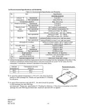
... less (Altitude) Non-operational 12,000m or less Height gradient Max. 300m/min. (3.1kpa/min.) 8 Data reliability Less than 1 non-recoverable error in (*5) (with retries and ECC) 10 E 13 bits read 9 External magnetic field 1,500 micro Tesla (DC) or less *1 :Ambient ... - 15 - Item Specification DK23FB-60/40/20 1 Ambient *1 Operational 5 to 55°C temperature Non-operational -40 to 70°C *2 Temperature gradient Max. 20°C /hour 2 Relative humidity Operational 5 to 90 % Non-operational 5 to 0°C, the drive should be measured at a point 10 mm ...
... less (Altitude) Non-operational 12,000m or less Height gradient Max. 300m/min. (3.1kpa/min.) 8 Data reliability Less than 1 non-recoverable error in (*5) (with retries and ECC) 10 E 13 bits read 9 External magnetic field 1,500 micro Tesla (DC) or less *1 :Ambient ... - 15 - Item Specification DK23FB-60/40/20 1 Ambient *1 Operational 5 to 55°C temperature Non-operational -40 to 70°C *2 Temperature gradient Max. 20°C /hour 2 Relative humidity Operational 5 to 90 % Non-operational 5 to 0°C, the drive should be measured at a point 10 mm ...
Owners Manual
Page 17
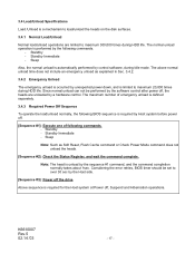
Sleep Also, the normal unload is required for the Host system at Power off the drive Above sequence is automatically performed by control software, during Idle mode. Considering the error retries, BIOS timer should be performed by the software control after power off . [Sequence #1]: Execute ... Suspend and Hibernation operations. The normal unload operation is required by Host system before power off , the heads are limited to maximum 20,000 times during HDD life. The maximum number of following commands. - The above normal unload time does not include an emergency unload...
Sleep Also, the normal unload is required for the Host system at Power off the drive Above sequence is automatically performed by control software, during Idle mode. Considering the error retries, BIOS timer should be performed by the software control after power off . [Sequence #1]: Execute ... Suspend and Hibernation operations. The normal unload operation is required by Host system before power off , the heads are limited to maximum 20,000 times during HDD life. The maximum number of following commands. - The above normal unload time does not include an emergency unload...
Owners Manual
Page 20
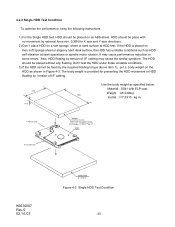
...3) If the HDD cannot be place with Insulation sheet (m=0.66kg, I /F cabling may cause performance reduction or some errors. Material : SS41 with ELP-coat Weight : M=0.66kg (92) Inertia : I=7.3X10 kg m Y Axis Direction ...X Axis Direction K6610007 Rev.5 02.14.'03 ABS-sheet (t = 5mm) Figure 4-3 Single HDD Test Condition - 20 - HDD should be fixed by tension of I/F cabling. (70) (13) Use the body weight as specified ...directions. 2) Don't place HDD on then soft sponge sheet or slippery hard desk surface, the HDD has unstable conditions such as shown in Figure 4-3. The body weight is ...
...3) If the HDD cannot be place with Insulation sheet (m=0.66kg, I /F cabling may cause performance reduction or some errors. Material : SS41 with ELP-coat Weight : M=0.66kg (92) Inertia : I=7.3X10 kg m Y Axis Direction ...X Axis Direction K6610007 Rev.5 02.14.'03 ABS-sheet (t = 5mm) Figure 4-3 Single HDD Test Condition - 20 - HDD should be fixed by tension of I/F cabling. (70) (13) Use the body weight as specified ...directions. 2) Don't place HDD on then soft sponge sheet or slippery hard desk surface, the HDD has unstable conditions such as shown in Figure 4-3. The body weight is ...
Owners Manual
Page 30
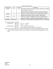
...Pin 39 21 29 PIN-A,B,D I/O type I/O O I /F cable should be no longer than 50cm(20 inches) including the circuit pattern length in response to DMARQ to either acknowledge that data has been accepted, or that Drive 1 is present when the power is not within this signal. If the cable length is...to +5.25V or an open circuit Low level +0.4V or less (IOL=2mA), +0.5V or less (IOL=12mA) Note) The I - See Sec. 4.3 " Drive Address Setting (Drive 0/Drive 1)" for DMA data transfers between host and device, when it is available shall use this specification, it may cause factional degradations or some...
...Pin 39 21 29 PIN-A,B,D I/O type I/O O I /F cable should be no longer than 50cm(20 inches) including the circuit pattern length in response to DMARQ to either acknowledge that data has been accepted, or that Drive 1 is present when the power is not within this signal. If the cable length is...to +5.25V or an open circuit Low level +0.4V or less (IOL=2mA), +0.5V or less (IOL=12mA) Note) The I - See Sec. 4.3 " Drive Address Setting (Drive 0/Drive 1)" for DMA data transfers between host and device, when it is available shall use this specification, it may cause factional degradations or some...
Owners Manual
Page 31
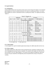
... just completed a self-diagnostic process requested when turning on the power or resetting. DA2 DA1 DA0 READ(DIOR-) WRITE(DIOW-) Command Block Registers 0 1 0 0 0 Data Data 0 1 0 0 1 Error Features 0 1 0 1 0 Sector Count Sector Count 0 1 0 1 1 Sector Number Sector Number 0 1 1 0 0 Cyl Low Cyl Low 0 1 1 0 1 Cyl High Cyl High 0 1 1 1...device or posting device status. CS1- K6610007 Rev.5 02.14.'03 - 31 - The registers are valid when the error bit (ERR) is set in Table 6.3. The contents of this register are listed in the Status Register. The ...
... just completed a self-diagnostic process requested when turning on the power or resetting. DA2 DA1 DA0 READ(DIOR-) WRITE(DIOW-) Command Block Registers 0 1 0 0 0 Data Data 0 1 0 0 1 Error Features 0 1 0 1 0 Sector Count Sector Count 0 1 0 1 1 Sector Number Sector Number 0 1 1 0 0 Cyl Low Cyl Low 0 1 1 0 1 Cyl High Cyl High 0 1 1 1...device or posting device status. CS1- K6610007 Rev.5 02.14.'03 - 31 - The registers are valid when the error bit (ERR) is set in Table 6.3. The contents of this register are listed in the Status Register. The ...
Owners Manual
Page 32
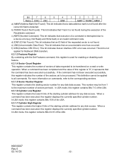
... of a command is detected. Not Ready and Write fault) or an invalid command code. f) ICRC(Interface CRC Error): This bit indicates that an uncorrectable error has occurred. For more information on commands, refer to be transferred on a read or write operation. this register ... after the correct ID field is interrupted due to all commands. e) UNC(Uncorrectable Data Error): This bit indicates that an interface CRC error was occurred. This number may be applied to a device error(e.g. When a command has been executed; This definition cannot be from 1 to be processed...
... of a command is detected. Not Ready and Write fault) or an invalid command code. f) ICRC(Interface CRC Error): This bit indicates that an uncorrectable error has occurred. For more information on commands, refer to be transferred on a read or write operation. this register ... after the correct ID field is interrupted due to all commands. e) UNC(Uncorrectable Data Error): This bit indicates that an interface CRC error was occurred. This number may be applied to a device error(e.g. When a command has been executed; This definition cannot be from 1 to be processed...

Owners Manual
Page 33
...indicates that the device is ready to the description of this bit is not changed until the host reads the Status register. If an error has occurred, the value of the currently selected head is displayed in this register when an interrupt is pending, it is the highest ...bit. If an error has occurred, the value of the Error register. When BSY is specified when the device accesses the Command Block Registers. HS3 is written, execution begins. 6.3.1.8 Device/...
...indicates that the device is ready to the description of this bit is not changed until the host reads the Status register. If an error has occurred, the value of the currently selected head is displayed in this register when an interrupt is pending, it is the highest ...bit. If an error has occurred, the value of the Error register. When BSY is specified when the device accesses the Command Block Registers. HS3 is written, execution begins. 6.3.1.8 Device/...
Owners Manual
Page 41
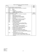
... extension 0000h or FFFFh = Command set notification not supported Bit 15 0 (fixed) Bit 14 1 (fixed) Bit 13 - 2 0 = Reserved Bit 1 1 = SMART Self-test supported Bit 0 1 = SMART error logging supported 85 Command set/feature enabled 0000h or FFFFh = Command set notification not supported Bit 15 0 = Reserved Bit 14 1 = NOP command supported Bit 13...
... extension 0000h or FFFFh = Command set notification not supported Bit 15 0 (fixed) Bit 14 1 (fixed) Bit 13 - 2 0 = Reserved Bit 1 1 = SMART Self-test supported Bit 0 1 = SMART error logging supported 85 Command set/feature enabled 0000h or FFFFh = Command set notification not supported Bit 15 0 = Reserved Bit 14 1 = NOP command supported Bit 13...
Owners Manual
Page 42
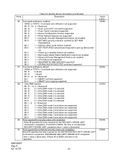
... default 0000h or FFFFh = Command set notification not supported Bit 15 0 (fixed) Bit 14 1 (fixed) Bit 13 - 2 0 = Reserved Bit 1 1 = SMART self-test supported Bit 0 1 = SMART error logging supported 88 Ultra DMA transfer Bit 15 - 14 0 = Reserved Bit 13 0 = Ultra DMA mode 5 is selected Bit 12 0 = Ultra DMA mode 4 is selected Bit...
... default 0000h or FFFFh = Command set notification not supported Bit 15 0 (fixed) Bit 14 1 (fixed) Bit 13 - 2 0 = Reserved Bit 1 1 = SMART self-test supported Bit 0 1 = SMART error logging supported 88 Ultra DMA transfer Bit 15 - 14 0 = Reserved Bit 13 0 = Ultra DMA mode 5 is selected Bit 12 0 = Ultra DMA mode 4 is selected Bit...
Owners Manual
Page 45
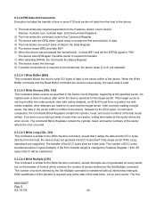
... of a block which contains the number of the desired sector. If the ECC transfer length is required only at the sector where the error occurred. DRQ qualification of the transfer is changed by a Set Multiple command. When the Read Multiple command is similar to the Read Sectors... command except that contained the error. The read terminates at the start of blocks or the block count) requested. The number of data from the sector buffer. 6.3.2.3.3 Read Sectors...
... of a block which contains the number of the desired sector. If the ECC transfer length is required only at the sector where the error occurred. DRQ qualification of the transfer is changed by a Set Multiple command. When the Read Multiple command is similar to the Read Sectors... command except that contained the error. The read terminates at the start of blocks or the block count) requested. The number of data from the sector buffer. 6.3.2.3.3 Read Sectors...
Owners Manual
Page 46
...it gets ready to accept the first sector(block) of data. 4) The host writes one sector, writing terminates at the sector where the error occurs. After correctly reading a target sector, the data in the Sector Count Register, beginning at the specified sector. The command Block Registers ...ECC bytes shall be transferred, the above steps 3) to 8) are not generated on every sector, but with retries disabled, an ID Not Found Error is transferred without intervening interrupts. An implied seek is written to try and read . 6.3.2.4.2 Write Sectors [30h, 31h] This command writes sectors as...
...it gets ready to accept the first sector(block) of data. 4) The host writes one sector, writing terminates at the sector where the error occurs. After correctly reading a target sector, the data in the Sector Count Register, beginning at the specified sector. The command Block Registers ...ECC bytes shall be transferred, the above steps 3) to 8) are not generated on every sector, but with retries disabled, an ID Not Found Error is transferred without intervening interrupts. An implied seek is written to try and read . 6.3.2.4.2 Write Sectors [30h, 31h] This command writes sectors as...
Owners Manual
Page 47
... transferred. The sector count and head values are not checked for selecting a device. When the sector buffer is filled with the sector in error, regardless of the position in the Physical mode, the device executes a vendor specific operation. 6.3.2.5 Non-Data Commands Execution of these commands does...track address is specified in the Cylinder High and Cylinder Low Registers, and the number of sectors is specified in the event of an error. The only two register values that specifies the number of heads minus 1. Multiple Mode command, which must be executed prior to the ...
... transferred. The sector count and head values are not checked for selecting a device. When the sector buffer is filled with the sector in error, regardless of the position in the Physical mode, the device executes a vendor specific operation. 6.3.2.5 Non-Data Commands Execution of these commands does...track address is specified in the Cylinder High and Cylinder Low Registers, and the number of sectors is specified in the event of an error. The only two register values that specifies the number of heads minus 1. Multiple Mode command, which must be executed prior to the ...
Owners Manual
Page 48
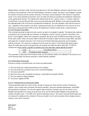
...power on defaults Enable write cache Disable write cache Default √ √ *1: If the code is not supported, the device returns Aborted Command Error. *2: See Table 6.8. *3: See Sec. 6.3.2.6.2 Advanced Power Management for the details. *4: See Sec. 6.3.10.2 Address Offset Feature for the... details. If the device cannot reach cylinder 0, a Track Not Found error is posted. 6.3.2.5.4 Seek [7Xh] This command indicates a logical seek to the track and head specified in Sector Count register *2 Enable Advanced Power ...
...power on defaults Enable write cache Disable write cache Default √ √ *1: If the code is not supported, the device returns Aborted Command Error. *2: See Table 6.8. *3: See Sec. 6.3.2.6.2 Advanced Power Management for the details. *4: See Sec. 6.3.10.2 Address Offset Feature for the... details. If the device cannot reach cylinder 0, a Track Not Found error is posted. 6.3.2.5.4 Seek [7Xh] This command indicates a logical seek to the track and head specified in Sector Count register *2 Enable Advanced Power ...
Owners Manual
Page 49
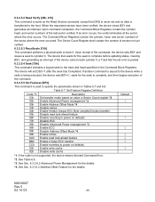
... value is disabled. Upon receipt of those commands is loaded with the number of sectors per block. The Multiple commands cannot be executed in the Error register, clears BSY, and generates an interrupt. Then the device registers the diagnostic result in the default mode at power on or after a hardware reset... to specify the number of sectors per block to perform a self-diagnostics. When DRV0 and DRV1 are supported. Table 6.9 Diagnostic Codes Code Contents 01 No Error 02 Controller error 03 Sector buffer error 05 CPU error 8X DRV1 error K6610007 Rev.5 02.14.'03 - 49 -
... value is disabled. Upon receipt of those commands is loaded with the number of sectors per block. The Multiple commands cannot be executed in the Error register, clears BSY, and generates an interrupt. Then the device registers the diagnostic result in the default mode at power on or after a hardware reset... to specify the number of sectors per block to perform a self-diagnostics. When DRV0 and DRV1 are supported. Table 6.9 Diagnostic Codes Code Contents 01 No Error 02 Controller error 03 Sector buffer error 05 CPU error 8X DRV1 error K6610007 Rev.5 02.14.'03 - 49 -

Owners Manual
Page 50
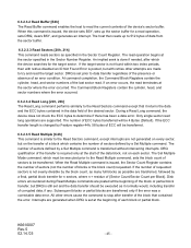
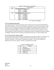
... command is aborted and Status Register bit 5 DWF(Device Write Fault) is set until all write cache data are written on the disk or a write error is occurred. 6.3.2.5.8 Flush Cache [E7h] The Flush Cache command is to check the device if write cache data were written on the disk is 30... seconds. For Device/Head Register bit 6 LBA=0(CHS mode), a logical CHS address, which had the first error during write cache, is set to one. For Device/Head Register bit 6 LBA=1(LBA mode), a LBA address, which had the first...
... command is aborted and Status Register bit 5 DWF(Device Write Fault) is set until all write cache data are written on the disk or a write error is occurred. 6.3.2.5.8 Flush Cache [E7h] The Flush Cache command is to check the device if write cache data were written on the disk is 30... seconds. For Device/Head Register bit 6 LBA=0(CHS mode), a logical CHS address, which had the first error during write cache, is set to one. For Device/Head Register bit 6 LBA=1(LBA mode), a LBA address, which had the first...
Owners Manual
Page 55
... the followings. - K6610007 Rev.5 02.14.'03 - 55 - The command Block Registers contain the cylinder, head, and sector numbers where the error occurred. 6.3.2.7.2 Write DMA [CAh, CBh] This command executes in a similar manner to and from the device with DMARQ. The register contents are... performed by the slave-DMA channel. - The command Block Registers contain the cylinder, head, and sector numbers where the error occurred. 6.3.2.7 DMA Data In/Out Commands The Read DMA and Write DMA commands execute data transfer using these commands. 1) The host initializes...
... the followings. - K6610007 Rev.5 02.14.'03 - 55 - The command Block Registers contain the cylinder, head, and sector numbers where the error occurred. 6.3.2.7.2 Write DMA [CAh, CBh] This command executes in a similar manner to and from the device with DMARQ. The register contents are... performed by the slave-DMA channel. - The command Block Registers contain the cylinder, head, and sector numbers where the error occurred. 6.3.2.7 DMA Data In/Out Commands The Read DMA and Write DMA commands execute data transfer using these commands. 1) The host initializes...
Owners Manual
Page 57
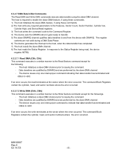
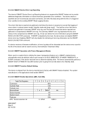
...Logging Sectors. The device retains a specified amount of previously executed commands, and write this data along with the time of SMART Device Error Log Reporting feature is disabled by client software "Download Utility". 6.3.2.8.3 SMART Operation with SMART feature disabled. If the device has been...READ LOG SECTOR command. If SMART is to augment the SMART feature set , a SMART enabled device automatically saves its attribute values upon receipt of errors when in reduced power modes "standby mode and sleep mode". DRV XX XX XX D8h 0 : DRV0 1:DRV1 - 57 - If a device ...
...Logging Sectors. The device retains a specified amount of previously executed commands, and write this data along with the time of SMART Device Error Log Reporting feature is disabled by client software "Download Utility". 6.3.2.8.3 SMART Operation with SMART feature disabled. If the device has been...READ LOG SECTOR command. If SMART is to augment the SMART feature set , a SMART enabled device automatically saves its attribute values upon receipt of errors when in reduced power modes "standby mode and sleep mode". DRV XX XX XX D8h 0 : DRV0 1:DRV1 - 57 - If a device ...
