
Owners Manual
Page 7
... D9h] 58 6.3.2.8.7 SMART Return Status [B0h, Sub DAh] 59 6.3.2.8.8 SMART Enable/Disable Attribute AUTOSAVE [B0h, Sub D2h 59 6.3.2.8.9 SMART Save Attribute Values [B0h, Sub D3h] 60 6.3.2.8.10 SMART Enable/Disable Automatic Off-line [B0h, Sub DBh 61 6.3.2.8.11 SMART Execute Off-line Immediate [B0h, Sub D4h 62 K6610007 Rev.5 02.14.'03...
... D9h] 58 6.3.2.8.7 SMART Return Status [B0h, Sub DAh] 59 6.3.2.8.8 SMART Enable/Disable Attribute AUTOSAVE [B0h, Sub D2h 59 6.3.2.8.9 SMART Save Attribute Values [B0h, Sub D3h] 60 6.3.2.8.10 SMART Enable/Disable Automatic Off-line [B0h, Sub DBh 61 6.3.2.8.11 SMART Execute Off-line Immediate [B0h, Sub D4h 62 K6610007 Rev.5 02.14.'03...
Owners Manual
Page 15
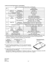
... be packed in the table below. Item Specification DK23FB-60/40/20 1 Ambient *1 Operational 5 to 55°C temperature Non-operational -40 to 70°C *2 Temperature gradient Max. 20°C /hour 2 Relative humidity Operational 5 to 90 % Non-operational 5 to 0°C, the drive should be measured at point 10 mm away from the nameplate, a substitution method is...
... be packed in the table below. Item Specification DK23FB-60/40/20 1 Ambient *1 Operational 5 to 55°C temperature Non-operational -40 to 70°C *2 Temperature gradient Max. 20°C /hour 2 Relative humidity Operational 5 to 90 % Non-operational 5 to 0°C, the drive should be measured at point 10 mm away from the nameplate, a substitution method is...
Owners Manual
Page 22
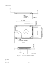
3±0.25 4.07±0.25 10.14±0.375 69.85±0.25 Drive width at mounting (70.1 Maximum drive width) 9.5 ± 0.2 2 4.4 Dimensions 4-M3 3.5mm min. full thread 76.6 ± 0.25 14.0 ± 0.25 10.24 ± 0.25 61.72±0.25 4-M3 3.0mm min. full thread 100±0.45 3.99±0.25 K6610007 Rev.5 02.14.'03 2 42 (Unit : mm) Figure 4-4 Dimensions (DK23FB-60/40/20) - 22 -
3±0.25 4.07±0.25 10.14±0.375 69.85±0.25 Drive width at mounting (70.1 Maximum drive width) 9.5 ± 0.2 2 4.4 Dimensions 4-M3 3.5mm min. full thread 76.6 ± 0.25 14.0 ± 0.25 10.24 ± 0.25 61.72±0.25 4-M3 3.0mm min. full thread 100±0.45 3.99±0.25 K6610007 Rev.5 02.14.'03 2 42 (Unit : mm) Figure 4-4 Dimensions (DK23FB-60/40/20) - 22 -
Owners Manual
Page 38
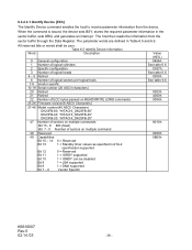
...Specific configuration 3 Number of logical heads 4 - 5 Retired 6 Number of logical sectors per logical track 7-9 Vendor specific 10-19 Serial number (20 ASCII characters) 20 Retired 21 Retired 22 Number of ECC bytes passed on READ/WRITE LONG commands 23-26 Firmware revision(8 ASCII Characters) 27...-46 Model number(40 ASCII Characters) DK23FB-60: "HITACHI_DK23FB-60" DK23FB-40: "HITACHI_DK23FB-40" DK23FB-20: "HITACHI_DK23FB-20" 47 Number of sectors on multiple commands Bit 15 - 8 80h (fixed) Bit 7 - 0 Number ...
...Specific configuration 3 Number of logical heads 4 - 5 Retired 6 Number of logical sectors per logical track 7-9 Vendor specific 10-19 Serial number (20 ASCII characters) 20 Retired 21 Retired 22 Number of ECC bytes passed on READ/WRITE LONG commands 23-26 Firmware revision(8 ASCII Characters) 27...-46 Model number(40 ASCII Characters) DK23FB-60: "HITACHI_DK23FB-60" DK23FB-40: "HITACHI_DK23FB-40" DK23FB-20: "HITACHI_DK23FB-20" 47 Number of sectors on multiple commands Bit 15 - 8 80h (fixed) Bit 7 - 0 Number ...
Owners Manual
Page 44
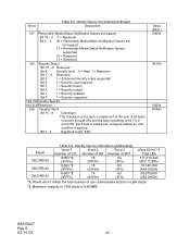
...Bit 7 - 0 Signature Code "A5h" Value (HEX.) 0000h 0XXXh 0000h XXA5h Model DK23FB-60 DK23FB-40 DK23FB-20 Table 6.6 Identify Device information (Addressing) Word 1 Word 2 Word 3 Number of CYL. Word... Table 6.5 Identify Device Information(Continued) Description 127 Removable Media Status Notification feature set support Bit 15 - 2 0 = Reserved Bit 1 - 0 00 = Removable Media Status Notification feature set not support 01 = Removable Media Status Notification feature supported 10...
...Bit 7 - 0 Signature Code "A5h" Value (HEX.) 0000h 0XXXh 0000h XXA5h Model DK23FB-60 DK23FB-40 DK23FB-20 Table 6.6 Identify Device information (Addressing) Word 1 Word 2 Word 3 Number of CYL. Word... Table 6.5 Identify Device Information(Continued) Description 127 Removable Media Status Notification feature set support Bit 15 - 2 0 = Reserved Bit 1 - 0 00 = Removable Media Status Notification feature set not support 01 = Removable Media Status Notification feature supported 10...

Owners Manual
Page 102
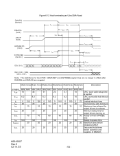
Figure 6-10 Host pausing an Ultra DMA Read DMARQ (device) DMACK(host) STOP tRP (host) HDMARDY(host) tRFS DSTROBE (device) DD(15:0) (device) Note: The host asserts STOP to -pause time K6610007 Rev.5 02.14.'03 - 102 - SYMBOL tRFS tRP Mode 0(ns) Mode 1(ns) Mode 2(ns) Mode3(ns) MIN MAX MIN MAX MIN MAX MIN MAX 75 70 60 60 160 125 100 100 Mode4(ns) MIN MAX 60 100 Mode5(ns) Description MIN MAX 50 Ready-to-final STROBE time 85 Ready-to request termination of the Ultra DMA burst no sooner than tRP after HDMARDYis negated.
Figure 6-10 Host pausing an Ultra DMA Read DMARQ (device) DMACK(host) STOP tRP (host) HDMARDY(host) tRFS DSTROBE (device) DD(15:0) (device) Note: The host asserts STOP to -pause time K6610007 Rev.5 02.14.'03 - 102 - SYMBOL tRFS tRP Mode 0(ns) Mode 1(ns) Mode 2(ns) Mode3(ns) MIN MAX MIN MAX MIN MAX MIN MAX 75 70 60 60 160 125 100 100 Mode4(ns) MIN MAX 60 100 Mode5(ns) Description MIN MAX 50 Ready-to-final STROBE time 85 Ready-to request termination of the Ultra DMA burst no sooner than tRP after HDMARDYis negated.
Owners Manual
Page 104
... 75 70 60 60 60 50 Ready-to-final-STROBE time tRP 160 125 100 100 100 85 Ready-to-pause time tIORDYZ 20 20 20 20 20 20 Maximum time before releasing IORDY tACK 20 20 20 20 20 20 Setup and hold time at sender tLI 0 150 0 150 0 150 0 100 0 100 0 75 Limited interlock time tMLI 20 20 20 20 20 20 Interlock time with minimum tAZ 10 10 10 10 10 10 Maximum time...
... 75 70 60 60 60 50 Ready-to-final-STROBE time tRP 160 125 100 100 100 85 Ready-to-pause time tIORDYZ 20 20 20 20 20 20 Maximum time before releasing IORDY tACK 20 20 20 20 20 20 Setup and hold time at sender tLI 0 150 0 150 0 150 0 100 0 100 0 75 Limited interlock time tMLI 20 20 20 20 20 20 Interlock time with minimum tAZ 10 10 10 10 10 10 Maximum time...

Owners Manual
Page 109
... 70 48 31 20 6.7 10 CRC word valid setup time at sender tCVH 6.2 6.2 6.2 6.2 6.2 10 CRC word valid hold time at sender tLI 0 150 0 150 0 150 0 100 0 100 0 75 Limited interlock time tMLI 20 20 20 20 20 20 Interlock time with minimum tRFS 75 70 60 60 60 50 Ready-to -pause time tIORDYZ 20 20 20 20 20 20 Maximum time before releasing IORDY tACK 20 20 20 20 20 20 Setup and...
... 70 48 31 20 6.7 10 CRC word valid setup time at sender tCVH 6.2 6.2 6.2 6.2 6.2 10 CRC word valid hold time at sender tLI 0 150 0 150 0 150 0 100 0 100 0 75 Limited interlock time tMLI 20 20 20 20 20 20 Interlock time with minimum tRFS 75 70 60 60 60 50 Ready-to -pause time tIORDYZ 20 20 20 20 20 20 Maximum time before releasing IORDY tACK 20 20 20 20 20 20 Setup and...