
Owners Manual
Page 4
...void if the breather hole was covered with the interface connector pins. This product is max. 10 A for the protection. 12. The requirement of data. Improper insertion of the drive (Printed pattern, component lead, etc. If a foreign conductive substance (metallic powder, fluid, etc.) adheres to circuit or .... 10. Handle with insulation sheet if the active metal of host system may cause bodily injury. Caution 5. Shock can damage the drive. Don't open the HDA or break any broken HDA seals. Also, pins or HDA corners may cause catastrophic failures. Do not ...
...void if the breather hole was covered with the interface connector pins. This product is max. 10 A for the protection. 12. The requirement of data. Improper insertion of the drive (Printed pattern, component lead, etc. If a foreign conductive substance (metallic powder, fluid, etc.) adheres to circuit or .... 10. Handle with insulation sheet if the active metal of host system may cause bodily injury. Caution 5. Shock can damage the drive. Don't open the HDA or break any broken HDA seals. Also, pins or HDA corners may cause catastrophic failures. Do not ...
Owners Manual
Page 6
...4.0 Installation 4.1 Installation Direction 4.2 Mounting HDD 4.2.1 Mounting HDD with Screws 4.2.2 Single HDD Test Condition 4.2.3 Attention for HDD Installation 4.3 Drive Address Setting(DRIVE 0/DRIVE 1) 4.4 Dimensions 5.0 Packing and Handling 5.1 Packing 5.2 Handling 6.0 Interface 6.1 Power Interface 6.2 Physical Interface 6.2.1 Connector 6.2.2 Connector Pin... Register 6.3.1.11 Alternate Status Register 6.3.1.12 Device Control Register Page 2 9 9 10 12 13 13 15 16 17 17 17 17 18 18 19 19 20 21 21 22 23 23 24 25...
...4.0 Installation 4.1 Installation Direction 4.2 Mounting HDD 4.2.1 Mounting HDD with Screws 4.2.2 Single HDD Test Condition 4.2.3 Attention for HDD Installation 4.3 Drive Address Setting(DRIVE 0/DRIVE 1) 4.4 Dimensions 5.0 Packing and Handling 5.1 Packing 5.2 Handling 6.0 Interface 6.1 Power Interface 6.2 Physical Interface 6.2.1 Connector 6.2.2 Connector Pin... Register 6.3.1.11 Alternate Status Register 6.3.1.12 Device Control Register Page 2 9 9 10 12 13 13 15 16 17 17 17 17 18 18 19 19 20 21 21 22 23 23 24 25...

Owners Manual
Page 8
6.3.2.8.12 SMART Read Log Sector [B0h, Sub D5h] 65 6.3.2.8.13 SMART Write Log Sector [B0h, Sub D6h] 71 6.3.2.9 Security Mode Feature 72 6.3.2.9.1 Security Mode Default Setting ... 6.3.2.11.2 Device Configuration Freeze Lock [B1h, Sub 01h] 89 6.3.2.11.3 Device Configuration Identify [B1h, Sub 02h] 90 6.3.2.11.4 Device Configuration Set [B1h, Sub 03h] 92 6.3.2.12 Note for Write Cache and Auto Reallocation 96 6.4 Interface Signal Timing 97 6.4.1 Data Transfer Timing 97 6.4.2 Ultra DMA Data Transfer Timing 100 6.4.3 Power On and...
6.3.2.8.12 SMART Read Log Sector [B0h, Sub D5h] 65 6.3.2.8.13 SMART Write Log Sector [B0h, Sub D6h] 71 6.3.2.9 Security Mode Feature 72 6.3.2.9.1 Security Mode Default Setting ... 6.3.2.11.2 Device Configuration Freeze Lock [B1h, Sub 01h] 89 6.3.2.11.3 Device Configuration Identify [B1h, Sub 02h] 90 6.3.2.11.4 Device Configuration Set [B1h, Sub 03h] 92 6.3.2.12 Note for Write Cache and Auto Reallocation 96 6.4 Interface Signal Timing 97 6.4.1 Data Transfer Timing 97 6.4.2 Ultra DMA Data Transfer Timing 100 6.4.3 Power On and...
Owners Manual
Page 12
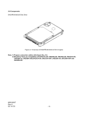
2.0 Components DK23FB-60/40/20 Disk Drive Figure 2-1 Overview of DK23FB-60/40/20 (9.5mm height) Note: 1) Prepare connection cables referring to Sec. 6.2. 2) Mounting holes are compatible with DK237A-XX, DK238A-XX, DK239A-XX, DK23AA-XX, DK23BA-xx, DK23BA-XXE,DK23CA-XX, DK23CA-XXF, DK23DA-XX, DK23DA-XXF and DK23EX-XX. K6610007 Rev.5 02.14.'03 - 12 -
2.0 Components DK23FB-60/40/20 Disk Drive Figure 2-1 Overview of DK23FB-60/40/20 (9.5mm height) Note: 1) Prepare connection cables referring to Sec. 6.2. 2) Mounting holes are compatible with DK237A-XX, DK238A-XX, DK239A-XX, DK23AA-XX, DK23BA-xx, DK23BA-XXE,DK23CA-XX, DK23CA-XXF, DK23DA-XX, DK23DA-XXF and DK23EX-XX. K6610007 Rev.5 02.14.'03 - 12 -
Owners Manual
Page 15
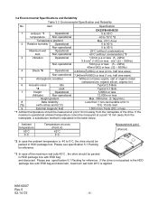
... organic tin) 6 Acoustic-noise Idle Typical 2.8 Bels *4 seek Typical 3.1 Bels 7 Height Operational 3,000m or less (Altitude) Non-operational 12,000m or less Height gradient Max. 300m/min. (3.1kpa/min.) 8 Data reliability Less than 1 non-recoverable error in (*5) (with ESD...or less (1 ms, half sine wave) 5 Atmospheric condition Without corrosive vapors, salt or organic-metal compound.(ex. If the drive is applied. Item Specification DK23FB-60/40/20 1 Ambient *1 Operational 5 to 55°C temperature Non-operational -40 to 70°C *2 Temperature gradient Max...
... organic tin) 6 Acoustic-noise Idle Typical 2.8 Bels *4 seek Typical 3.1 Bels 7 Height Operational 3,000m or less (Altitude) Non-operational 12,000m or less Height gradient Max. 300m/min. (3.1kpa/min.) 8 Data reliability Less than 1 non-recoverable error in (*5) (with ESD...or less (1 ms, half sine wave) 5 Atmospheric condition Without corrosive vapors, salt or organic-metal compound.(ex. If the drive is applied. Item Specification DK23FB-60/40/20 1 Ambient *1 Operational 5 to 55°C temperature Non-operational -40 to 70°C *2 Temperature gradient Max...

Owners Manual
Page 25
Typical Spin-up Current Transition 1.6 Current of +5V power 1.4 (A) 1.2 1.0 0.8 0.6 0.4 0.2 0.0 0 1 2 3 4 5 6 7 Time (sec) Figure 6-1 Power Current Transition Typical Spin-up Current Transition with Retry Retry 1.6 Current of +5V power 1.4 (A) 1.2 1.0 0.8 0.6 0.4 0.2 0.0 0 1 2 3 4 5 6 7 8 9 10 11 12 13 14 Time (sec) Figure 6-2 Power Current Transition with retries K6610007 Rev.5 02.14.'03 - 25 - 6.0 Interface 6.1 Power Interface Only +5VDC power is applied to this Device. Figures 6-1 and 6-2 show power current transitions after turning on the power.
Typical Spin-up Current Transition 1.6 Current of +5V power 1.4 (A) 1.2 1.0 0.8 0.6 0.4 0.2 0.0 0 1 2 3 4 5 6 7 Time (sec) Figure 6-1 Power Current Transition Typical Spin-up Current Transition with Retry Retry 1.6 Current of +5V power 1.4 (A) 1.2 1.0 0.8 0.6 0.4 0.2 0.0 0 1 2 3 4 5 6 7 8 9 10 11 12 13 14 Time (sec) Figure 6-2 Power Current Transition with retries K6610007 Rev.5 02.14.'03 - 25 - 6.0 Interface 6.1 Power Interface Only +5VDC power is applied to this Device. Figures 6-1 and 6-2 show power current transitions after turning on the power.
Owners Manual
Page 27
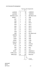
... 35 CS0- 37 DASP- 39 5VDC(Logic) 41 GND(Logic) 43 B JUMPER0 D JUMPER2 F KEY(Removed) 2 GND 4 DD8 6 DD9 8 DD10 10 DD11 12 DD12 14 DD13 16 DD14 18 DD15 20 KEY(Removed) 22 GND 24 GND 26 GND 28 CSEL 30 GND 32 IOCS16- 34 PDIAG- 36 DA2 38 CS1- 40 GND...
... 35 CS0- 37 DASP- 39 5VDC(Logic) 41 GND(Logic) 43 B JUMPER0 D JUMPER2 F KEY(Removed) 2 GND 4 DD8 6 DD9 8 DD10 10 DD11 12 DD12 14 DD13 16 DD14 18 DD15 20 KEY(Removed) 22 GND 24 GND 26 GND 28 CSEL 30 GND 32 IOCS16- 34 PDIAG- 36 DA2 38 CS1- 40 GND...

Owners Manual
Page 34
... nIEN is 1 or when the device is not selected, the INTRQ signal is enabled. b) SRST (Software Reset): When this register will not clear the interrupt. 6.3.1.12 Device Control Register This register includes the software reset bit and the interrupt enable bit. Reading this bit is set, the device is reset.
... nIEN is 1 or when the device is not selected, the INTRQ signal is enabled. b) SRST (Software Reset): When this register will not clear the interrupt. 6.3.1.12 Device Control Register This register includes the software reset bit and the interrupt enable bit. Reading this bit is set, the device is reset.
Owners Manual
Page 38
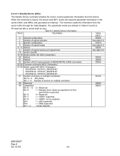
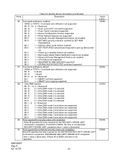
... Number of logical heads 4 - 5 Retired 6 Number of logical sectors per logical track 7-9 Vendor specific 10-19 Serial number (20 ASCII characters) 20 Retired 21 Retired 22 Number of ECC bytes passed on READ/WRITE LONG commands 23-26 Firmware revision(8 ASCII Characters) 27-46 Model ...-20" 47 Number of sectors on multiple commands Bit 15 - 8 80h (fixed) Bit 7 - 0 Number of sectors on multiple command 48 Reserved 49 Capabilities Bit 15 - 14 0 = Reserved Bit 13 1 = Standby timer values as specified in ATA-2 specification supported Bit 12 0 = Reserved Bit 11 1 = IORDY supported...
... Number of logical heads 4 - 5 Retired 6 Number of logical sectors per logical track 7-9 Vendor specific 10-19 Serial number (20 ASCII characters) 20 Retired 21 Retired 22 Number of ECC bytes passed on READ/WRITE LONG commands 23-26 Firmware revision(8 ASCII Characters) 27-46 Model ...-20" 47 Number of sectors on multiple commands Bit 15 - 8 80h (fixed) Bit 7 - 0 Number of sectors on multiple command 48 Reserved 49 Capabilities Bit 15 - 14 0 = Reserved Bit 13 1 = Standby timer values as specified in ATA-2 specification supported Bit 12 0 = Reserved Bit 11 1 = IORDY supported...
Owners Manual
Page 40
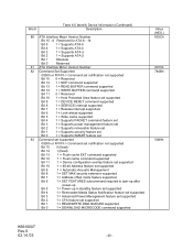
... or FFFFh = Command set notification not supported Bit 15 0 = Reserved Bit 14 1 = NOP command supported Bit 13 1 = READ BUFFER command supported Bit 12 1 = WRITE BUFFER command supported Bit 11 0 = Reserved Bit 10 1 = Host Protected Area feature set supported Bit 9 1 = DEVICE RESET command supported ...or FFFFh = Command set notification not supported Bit 15 0 (fixed) Bit 14 1 (fixed) Bit 13 1 = Flush cache EXT command supported Bit 12 1 = Flush cache command supported Bit 11 1 = Device configuration overlay feature set supported Bit 10 1 = 48-bit Address feature set supported Bit ...
... or FFFFh = Command set notification not supported Bit 15 0 = Reserved Bit 14 1 = NOP command supported Bit 13 1 = READ BUFFER command supported Bit 12 1 = WRITE BUFFER command supported Bit 11 0 = Reserved Bit 10 1 = Host Protected Area feature set supported Bit 9 1 = DEVICE RESET command supported ...or FFFFh = Command set notification not supported Bit 15 0 (fixed) Bit 14 1 (fixed) Bit 13 1 = Flush cache EXT command supported Bit 12 1 = Flush cache command supported Bit 11 1 = Device configuration overlay feature set supported Bit 10 1 = 48-bit Address feature set supported Bit ...
Owners Manual
Page 41
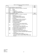
.../feature enabled 0000h or FFFFh = Command set notification not supported Bit 15 0 = Reserved Bit 14 1 = NOP command supported Bit 13 1 = READ BUFFER command supported Bit 12 1 = WRITE BUFFER command supported Bit 11 0 = Reserved Bit 10 1 = Host Protected Area feature set supported Bit 9 1 = DEVICE RESET command supported Bit 8 1 = SERVICE interrupt enabled Bit...
.../feature enabled 0000h or FFFFh = Command set notification not supported Bit 15 0 = Reserved Bit 14 1 = NOP command supported Bit 13 1 = READ BUFFER command supported Bit 12 1 = WRITE BUFFER command supported Bit 11 0 = Reserved Bit 10 1 = Host Protected Area feature set supported Bit 9 1 = DEVICE RESET command supported Bit 8 1 = SERVICE interrupt enabled Bit...
Owners Manual
Page 42
...set/feature enabled 0000h or FFFFh = Command set notification not supported Bit 15 -14 0 = Reserved Bit 13 1 = Flush cache EXT command supported Bit 12 1 = Flush Cache command supported Bit 11 1 = Device Configuration Overlay supported Bit 10 1 = 48-bit Address features set supported Bit 9 1 =... self-test supported Bit 0 1 = SMART error logging supported 88 Ultra DMA transfer Bit 15 - 14 0 = Reserved Bit 13 0 = Ultra DMA mode 5 is selected Bit 12 0 = Ultra DMA mode 4 is selected Bit 11 0 = Ultra DMA mode 3 is selected Bit 10 0 = Ultra DMA mode 2 is selected Bit 9 0 = Ultra ...
...set/feature enabled 0000h or FFFFh = Command set notification not supported Bit 15 -14 0 = Reserved Bit 13 1 = Flush cache EXT command supported Bit 12 1 = Flush Cache command supported Bit 11 1 = Device Configuration Overlay supported Bit 10 1 = 48-bit Address features set supported Bit 9 1 =... self-test supported Bit 0 1 = SMART error logging supported 88 Ultra DMA transfer Bit 15 - 14 0 = Reserved Bit 13 0 = Ultra DMA mode 5 is selected Bit 12 0 = Ultra DMA mode 4 is selected Bit 11 0 = Ultra DMA mode 3 is selected Bit 10 0 = Ultra DMA mode 2 is selected Bit 9 0 = Ultra ...
Owners Manual
Page 43
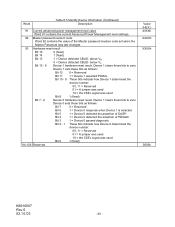
... Master password revision code set when the Master Password was last changed. 93 Hardware reset result Bit 15 0 (fixed) Bit 14 1 (fixed) Bit 13 Bit 12 - 8 1 = Device detected CBLID- Device 0 sets these bits to zero. above ViH 0 = Device detected CBLID- Word Table 6.5 Identify Device Information (Continued) Description 91 ...Power Management level settings. 92 Master password revision code Word 92 contains the value of DASP- Device 1 clears these bits as follows: Bit 12 0 = Reserved Bit 11 1 = Device 1 asserted PDIAG- below ViL Device 1 hardware reset result.
... Master password revision code set when the Master Password was last changed. 93 Hardware reset result Bit 15 0 (fixed) Bit 14 1 (fixed) Bit 13 Bit 12 - 8 1 = Device detected CBLID- Device 0 sets these bits to zero. above ViH 0 = Device detected CBLID- Word Table 6.5 Identify Device Information (Continued) Description 91 ...Power Management level settings. 92 Master password revision code Word 92 contains the value of DASP- Device 1 clears these bits as follows: Bit 12 0 = Reserved Bit 11 1 = Device 1 asserted PDIAG- below ViL Device 1 hardware reset result.

Owners Manual
Page 65
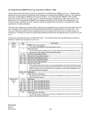
... returns the indicated log to store any data desired. Sector number - DRV XX Log Address Number of sector to be zeros. 6.3.2.8.12 SMART Read Log Sector [B0h, Sub D5h] Task File Registers Command Cylinder High Cylinder Low Device/Head Sector Number Sector Count Features ...DRV : Device selection bit 7 6 5 4 3 2 1 0 B0h C2h 4Fh - Table 6.12 Log Sector Addresses Log Sector Address Content Sector Size Read/Write 00h SMART Log Directory 1 Read Only 01h Summary SMART Error Log 1 Read Only 02h...
... returns the indicated log to store any data desired. Sector number - DRV XX Log Address Number of sector to be zeros. 6.3.2.8.12 SMART Read Log Sector [B0h, Sub D5h] Task File Registers Command Cylinder High Cylinder Low Device/Head Sector Number Sector Count Features ...DRV : Device selection bit 7 6 5 4 3 2 1 0 B0h C2h 4Fh - Table 6.12 Log Sector Addresses Log Sector Address Content Sector Size Read/Write 00h SMART Log Directory 1 Read Only 01h Summary SMART Error Log 1 Read Only 02h...

Owners Manual
Page 66
... most recent error. Error log index The error log index indicates the error log data structure representing the most recent error log structure. Byte n ~ n+11 n+12 ~ n+23 n+24 ~ n+35 n+36 ~ n+47 n+48 ~ n+59 n+60 ~ n+89 Table 6.14 Error log data structure Description First command data structure Second command data structure Third...
... most recent error. Error log index The error log index indicates the error log data structure representing the most recent error log structure. Byte n ~ n+11 n+12 ~ n+23 n+24 ~ n+35 n+36 ~ n+47 n+48 ~ n+59 n+60 ~ n+89 Table 6.14 Error log data structure Description First command data structure Second command data structure Third...
Owners Manual
Page 68
... error log data structure Fifth error log data structure Device error count This contains the total number of errors attributable to the receipt of section 6.3.2.8.12 (1) . (3) Comprehensive SMART Error Log [Log Sector Address = 02h] The last 255 errors that device reported are gathered in the first sector. K6610007 Rev.5 02.14...
... error log data structure Fifth error log data structure Device error count This contains the total number of errors attributable to the receipt of section 6.3.2.8.12 (1) . (3) Comprehensive SMART Error Log [Log Sector Address = 02h] The last 255 errors that device reported are gathered in the first sector. K6610007 Rev.5 02.14...
Owners Manual
Page 77
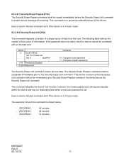
... content of this sector of this command is shown below. - Device returns Aborted command error if the device is in Frozen mode. DK23FB-20 : 44 minutes 28 minutes 12 minutes K6610007 Rev.5 02.14.'03 - 77 - The execution time of information. If the password does not match, then the device rejects the...
... content of this sector of this command is shown below. - Device returns Aborted command error if the device is in Frozen mode. DK23FB-20 : 44 minutes 28 minutes 12 minutes K6610007 Rev.5 02.14.'03 - 77 - The execution time of information. If the password does not match, then the device rejects the...

Owners Manual
Page 96
By this auto reallocation, the unrecoverable error sector is reassigned to a spare sector, and the data of the data into its cache buffer memory. 6.3.2.12 Note For Write Cache and Auto Reallocation (1) Loss of data in write cache Write cache is a performance enhancement whereby the device reports as completion the ...
By this auto reallocation, the unrecoverable error sector is reassigned to a spare sector, and the data of the data into its cache buffer memory. 6.3.2.12 Note For Write Cache and Auto Reallocation (1) Loss of data in write cache Write cache is a performance enhancement whereby the device reports as completion the ...
Owners Manual
Page 100
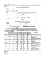
... transition of critical timing tDZFS 70 48 31 20 6.7 25 Time from STROBE output released-to -driving until DMARQ and DMACK are not in effect until the first transition of critical timing tACK 20 20 20 20 20 20 Setup and hold times before assertion and negation ... output drivers turning on tENV tZIORDY 20 70 20 70 20 70 20 55 20 55 20 50 Envelope time 0 0 0 0 0 0 Minimum time waiting before driving IORDY tZFS 0 0 0 0 0 35 Time from data output released- 6.4.2 Ultra DMA Data Transfer Timing Figures 6-8 through 6-12 and 6-13 through 17 define the...
... transition of critical timing tDZFS 70 48 31 20 6.7 25 Time from STROBE output released-to -driving until DMARQ and DMACK are not in effect until the first transition of critical timing tACK 20 20 20 20 20 20 Setup and hold times before assertion and negation ... output drivers turning on tENV tZIORDY 20 70 20 70 20 70 20 55 20 55 20 50 Envelope time 0 0 0 0 0 0 Minimum time waiting before driving IORDY tZFS 0 0 0 0 0 35 Time from data output released- 6.4.2 Ultra DMA Data Transfer Timing Figures 6-8 through 6-12 and 6-13 through 17 define the...
Owners Manual
Page 104
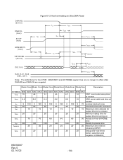
Figure 6-12 Host terminating an Ultra DMA Read DMARQ (device) DMACK(host) STOP (...60 50 Ready-to-final-STROBE time tRP 160 125 100 100 100 85 Ready-to release tZAH 20 20 20 20 20 20 Minimum delay time for the STOP, HDMARDY and DSTROBE signal lines are no longer in effect after DMARQ...20 20 20 20 20 20 Setup and hold time at sender tLI 0 150 0 150 0 150 0 100 0 100 0 75 Limited interlock time tMLI 20 20 20 20 20 20 Interlock time with minimum tAZ 10 10 10 10 10 10 Maximum time allowed for output drivers to -pause time tIORDYZ 20 20 20 20 20 20...
Figure 6-12 Host terminating an Ultra DMA Read DMARQ (device) DMACK(host) STOP (...60 50 Ready-to-final-STROBE time tRP 160 125 100 100 100 85 Ready-to release tZAH 20 20 20 20 20 20 Minimum delay time for the STOP, HDMARDY and DSTROBE signal lines are no longer in effect after DMARQ...20 20 20 20 20 20 Setup and hold time at sender tLI 0 150 0 150 0 150 0 100 0 100 0 75 Limited interlock time tMLI 20 20 20 20 20 20 Interlock time with minimum tAZ 10 10 10 10 10 10 Maximum time allowed for output drivers to -pause time tIORDYZ 20 20 20 20 20 20...