Instruction Manual
Page 4
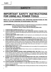
... NEAR THE WORK AREA. ALWAYS USE EYE PROTECTION WHEN WORKING WITH THE TOOL TO PREVENT EYE INJURY. Also, use the power tool in the moving parts. Always unplug unattended tools and keep proper footing and balance when working order. 2. Always wear non-slip footwear, preferably with the following safety rules: 1. Ordinary...
... NEAR THE WORK AREA. ALWAYS USE EYE PROTECTION WHEN WORKING WITH THE TOOL TO PREVENT EYE INJURY. Also, use the power tool in the moving parts. Always unplug unattended tools and keep proper footing and balance when working order. 2. Always wear non-slip footwear, preferably with the following safety rules: 1. Ordinary...

Instruction Manual
Page 5
...and before inserting the power plug into the tool against the rotation direction of the slide compound miter saw. 25. Always repair or replace any way. When servicing this Power Tool A...is wider than the other damaged components before using this tool. 16. ALWAYS CHECK FOR DAMAGED PARTS BEFORE USING THE TOOL. TURN POWER OFF. Always use outboard stands to provide support for ...that might affect proper operation. This tool was not designed to a complete stop . English 12. Always follow instructions for lubricating the tool and for the best and safest performance. ALWAYS CONFIRM...
...and before inserting the power plug into the tool against the rotation direction of the slide compound miter saw. 25. Always repair or replace any way. When servicing this Power Tool A...is wider than the other damaged components before using this tool. 16. ALWAYS CHECK FOR DAMAGED PARTS BEFORE USING THE TOOL. TURN POWER OFF. Always use outboard stands to provide support for ...that might affect proper operation. This tool was not designed to a complete stop . English 12. Always follow instructions for lubricating the tool and for the best and safest performance. ALWAYS CONFIRM...
Instruction Manual
Page 7
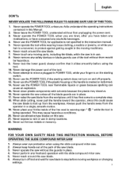
...parts, including the blade, while the saw blade from the workpiece until it slides smoothly before moving machinery. 6. Never operate the saw blade. 7. WARNING FOR YOUR OWN SAFETY READ THIS INSTRUCTION MANUAL BEFORE OPERATING THE SLIDE COMPOUND MITER SAW 1. Never reach around the saw blade. 3. use the POWER TOOL for saw...the slide compound miter saw blade to warning sign " c " while the tool is being operated. When slide cutting, never pull the handle toward the operator, since this could cause the saw . 21. Never use the POWER TOOL if the starting switch. 12. ...
...parts, including the blade, while the saw blade from the workpiece until it slides smoothly before moving machinery. 6. Never operate the saw blade. 7. WARNING FOR YOUR OWN SAFETY READ THIS INSTRUCTION MANUAL BEFORE OPERATING THE SLIDE COMPOUND MITER SAW 1. Never reach around the saw blade. 3. use the POWER TOOL for saw...the slide compound miter saw blade to warning sign " c " while the tool is being operated. When slide cutting, never pull the handle toward the operator, since this could cause the saw . 21. Never use the POWER TOOL if the starting switch. 12. ...
Instruction Manual
Page 8
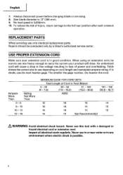
... - 150 (30.8 - 45.7) 18 16 16 14 18 16 14 12 16 16 14 12 14 12 Not Recommended & WARNING: Avoid electrical shock hazard. REPLACEMENT PARTS When servicing use depending on cord length and nameplate ampere rating. Table shows ...cord, be conducted only by a Hitachi authorized service center. If in good condition. Ampere More Than Rating Not More Than 0 - 6 6- 10 10 - 12 12 - 16 MINIMUM GAGE FOR CORD ... Always disconnect power before changing blade or servicing. 8. Saw blade diameter is 3,800/min. 10. Never use this tool with a damaged or ...
... - 150 (30.8 - 45.7) 18 16 16 14 18 16 14 12 16 16 14 12 14 12 Not Recommended & WARNING: Avoid electrical shock hazard. REPLACEMENT PARTS When servicing use depending on cord length and nameplate ampere rating. Table shows ...cord, be conducted only by a Hitachi authorized service center. If in good condition. Ampere More Than Rating Not More Than 0 - 6 6- 10 10 - 12 12 - 16 MINIMUM GAGE FOR CORD ... Always disconnect power before changing blade or servicing. 8. Saw blade diameter is 3,800/min. 10. Never use this tool with a damaged or ...
Instruction Manual
Page 9
... OWNERS OF THIS TOOL! 9 Although this system has no external grounding, you must still follow these precautions: * Only HITACHI AUTHORIZED SERVICE CENTER should disassemble or assemble this power tool, and only genuine HITACHI replacement parts should be installed. * Clean the exterior of this Instruction Manual, including not using the power tool in wet...
... OWNERS OF THIS TOOL! 9 Although this system has no external grounding, you must still follow these precautions: * Only HITACHI AUTHORIZED SERVICE CENTER should disassemble or assemble this power tool, and only genuine HITACHI replacement parts should be installed. * Clean the exterior of this Instruction Manual, including not using the power tool in wet...
Instruction Manual
Page 10
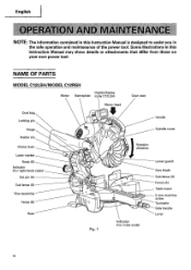
... Manual may show details or attachments that differ from those on your own power tool. NAME OF PARTS MODEL C12LSH/MODEL C12RSH Digital display Motor Nameplate (only C12LSH) Gear case Motor head Dust bag Locking pin Handle Hinge Spindle cover Holder (A) Clamp lever Laser ...marker Knob (B) Indicator (For right bevel scale) Set pin (A) Sub fence (B) Vise assembly Fence (B) Base UlEI 11/ Fig. 1 Rotation direction 0 Indicator (For miter scale) Lower guard Saw blade Sub...
... Manual may show details or attachments that differ from those on your own power tool. NAME OF PARTS MODEL C12LSH/MODEL C12RSH Digital display Motor Nameplate (only C12LSH) Gear case Motor head Dust bag Locking pin Handle Hinge Spindle cover Holder (A) Clamp lever Laser ...marker Knob (B) Indicator (For right bevel scale) Set pin (A) Sub fence (B) Vise assembly Fence (B) Base UlEI 11/ Fig. 1 Rotation direction 0 Indicator (For miter scale) Lower guard Saw blade Sub...
Instruction Manual
Page 13
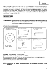
...motor head is located at the lower limit position. For further details, refer to "5. Cutting large workpieces" on the part of the HITACHI. 13 English When cutting the workpiece which has the dimension of "*" there might be dangerous and could cause injury ...or mechanical damage. Pay attention when cutting the workpiece. STANDARD ACCESSORIES IC) 12' (305 mm) TCT Saw blade (1 piece) (For wood) C) Dust bag (1 piece) 0 17 mm BOX wrench (1...
...motor head is located at the lower limit position. For further details, refer to "5. Cutting large workpieces" on the part of the HITACHI. 13 English When cutting the workpiece which has the dimension of "*" there might be dangerous and could cause injury ...or mechanical damage. Pay attention when cutting the workpiece. STANDARD ACCESSORIES IC) 12' (305 mm) TCT Saw blade (1 piece) (For wood) C) Dust bag (1 piece) 0 17 mm BOX wrench (1...
Instruction Manual
Page 15
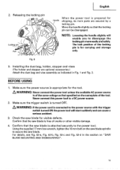
...in Fig. 1 and Fig. 2. Releasing the locking pin I Locking pin aset- Pull Handle When the power tool is attached securely to secure the saw blade. Check the saw blade spindle to the power tool. Using the supplied 17 mm box wrench, tighten the 10 mm bolt on the nameplate of cracks or... is prepared for the tool. WARNING: If the power cord is appropriate for shipping, its main parts are optional accessories.) Attach the dust bag and vise assembly as that the saw blade is turned OFF. Make sure the power source is connected to disengage the locking pin more easily and safely....
...in Fig. 1 and Fig. 2. Releasing the locking pin I Locking pin aset- Pull Handle When the power tool is attached securely to secure the saw blade. Check the saw blade spindle to the power tool. Using the supplied 17 mm box wrench, tighten the 10 mm bolt on the nameplate of cracks or... is prepared for the tool. WARNING: If the power cord is appropriate for shipping, its main parts are optional accessories.) Attach the dust bag and vise assembly as that the saw blade is turned OFF. Make sure the power source is connected to disengage the locking pin more easily and safely....
Instruction Manual
Page 40
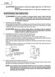
... to install saw blades larger than 12" (305 mm) in diameter or less. Always install saw blade immediately upon the first sign of carbon brush Code No. Inspecting the saw blade Always replace the saw blades that are expendable parts. A damaged saw blade can cause personal injury and a worn saw blade can ... to increase, making it to operate the power tool. 2. Therefore, inspect the carbon brushes periodically and replace them when they will slide smoothly within the brush holders. Such action is dull, its resistance to the hand pressure applied by exposing it unsafe to wash oil...
... to install saw blades larger than 12" (305 mm) in diameter or less. Always install saw blade immediately upon the first sign of carbon brush Code No. Inspecting the saw blade Always replace the saw blades that are expendable parts. A damaged saw blade can cause personal injury and a worn saw blade can ... to increase, making it to operate the power tool. 2. Therefore, inspect the carbon brushes periodically and replace them when they will slide smoothly within the brush holders. Such action is dull, its resistance to the hand pressure applied by exposing it unsafe to wash oil...

Instruction Manual
Page 41
...is in OFF position, (2) Power plug has been removed from the receptacle, When the tool is in good condition and that the following sliding surfaces once a month to the saw blade by loosening the four 5 mm screws (see Fig. 1 and Fig. 2). Replacement of Poly-V-Belt Poly-V-belt Pulley (A) 0 ...O Pulley (B) Fig. 55 The power of the pulley (A) and pulley (B). When connecting the belt on any loose part. & WARNING: To prevent personal ...
...is in OFF position, (2) Power plug has been removed from the receptacle, When the tool is in good condition and that the following sliding surfaces once a month to the saw blade by loosening the four 5 mm screws (see Fig. 1 and Fig. 2). Replacement of Poly-V-Belt Poly-V-belt Pulley (A) 0 ...O Pulley (B) Fig. 55 The power of the pulley (A) and pulley (B). When connecting the belt on any loose part. & WARNING: To prevent personal ...

Instruction Manual
Page 42
... of the power tool, especially from the inside of the motor, protect it from normal use. To assure that only authorized replacement parts will be performed by an AUTHORIZED HITACHI POWER TOOL REPAIR CENTER ONLY. To avoid a malfunction of the lower guard with a damp, soapy cloth. Cleaning Periodically remove chips, dust and...
... of the power tool, especially from the inside of the motor, protect it from normal use. To assure that only authorized replacement parts will be performed by an AUTHORIZED HITACHI POWER TOOL REPAIR CENTER ONLY. To avoid a malfunction of the lower guard with a damp, soapy cloth. Cleaning Periodically remove chips, dust and...
Parts List
Page 1
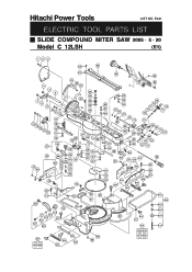
Hitachi Power Tools LIST NO. E941 ELECTRIC TOOL PARTS LIST SLIDE COMPOUND MITER SAW 2005 • 5 • 20 Model C 12LSH (E1) 123 60 62 61 63 64 4 5 6 4 8 9 10 11 12 17 13 18 14 15 12 16 15 11 10 38 37 47 48 45 44 46 49 50 51 19 20 21 65 A 23 24 69 7 22 25...
Hitachi Power Tools LIST NO. E941 ELECTRIC TOOL PARTS LIST SLIDE COMPOUND MITER SAW 2005 • 5 • 20 Model C 12LSH (E1) 123 60 62 61 63 64 4 5 6 4 8 9 10 11 12 17 13 18 14 15 12 16 15 11 10 38 37 47 48 45 44 46 49 50 51 19 20 21 65 A 23 24 69 7 22 25...
Parts List
Page 4
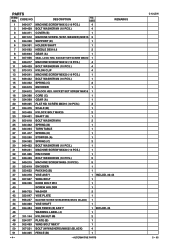
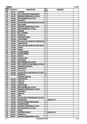
... M6 2 48 324-377 PLATE (B) 1 49 302-459 WING BOLT M6X17 1 50 307-221 BOLT (W/WASHERS) M8X35 (BLACK) 4 51 324-385 FENCE (B) 1 --- 4 --- * ALTERNATIVE PARTS C 12LSH 5 -- 05 DESCRIPTION NO. SOCKET SET SCREW M6X10 1 10 949-217 MACHINE SCREW M4X12 (10 PCS.) 4 11 949-429 BOLT WASHER M4 (10 PCS....) 4 12 973-313 NYLON CLIP 4 13 949-241 MACHINE SCREW M5X20 (10 PCS.) 1 14 949-432 BOLT WASHER M6 (10 PCS.) 1 15 324-392 SPRING (C) ...
... M6 2 48 324-377 PLATE (B) 1 49 302-459 WING BOLT M6X17 1 50 307-221 BOLT (W/WASHERS) M8X35 (BLACK) 4 51 324-385 FENCE (B) 1 --- 4 --- * ALTERNATIVE PARTS C 12LSH 5 -- 05 DESCRIPTION NO. SOCKET SET SCREW M6X10 1 10 949-217 MACHINE SCREW M4X12 (10 PCS.) 4 11 949-429 BOLT WASHER M4 (10 PCS....) 4 12 973-313 NYLON CLIP 4 13 949-241 MACHINE SCREW M5X20 (10 PCS.) 1 14 949-432 BOLT WASHER M6 (10 PCS.) 1 15 324-392 SPRING (C) ...
Parts List
Page 5
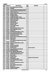
...-432 BOLT WASHER M6 (10 PCS.) 3 78 949-556 NUT M6 (10 PCS.) 1 79 324-409 KNOB (A) 1 80 950-817 METAL D8X10 2 81 324-406 BEVEL GEAR 2 82 949-454 SPRING WASHER M5 (10 PCS.) 4 83 949-241 MACHINE SCREW M5X20 (10 PCS.) 4 84 LABEL (A) 1 85 321-339 LEVER SHAFT 1... 1 INCLUD. 95 1 1 1 3 1 131 949-217 MACHINE SCREW M4X12 (10 PCS.) 1 132 949-429 BOLT WASHER M4 (10 PCS.) 1 133 948-193 NYLON CLIP 2 5 -- 05 * ALTERNATIVE PARTS C 12LSH --- 5 --- SCREW M6X25 (10 PCS.) 2 54 998-834 HOLDER 1 55 949-610 BOLT M6X10 (10 PCS.) 1 56 323-604 GEAR (A) 1 57 323-603 PACKING (A) 1 58...
...-432 BOLT WASHER M6 (10 PCS.) 3 78 949-556 NUT M6 (10 PCS.) 1 79 324-409 KNOB (A) 1 80 950-817 METAL D8X10 2 81 324-406 BEVEL GEAR 2 82 949-454 SPRING WASHER M5 (10 PCS.) 4 83 949-241 MACHINE SCREW M5X20 (10 PCS.) 4 84 LABEL (A) 1 85 321-339 LEVER SHAFT 1... 1 INCLUD. 95 1 1 1 3 1 131 949-217 MACHINE SCREW M4X12 (10 PCS.) 1 132 949-429 BOLT WASHER M4 (10 PCS.) 1 133 948-193 NYLON CLIP 2 5 -- 05 * ALTERNATIVE PARTS C 12LSH --- 5 --- SCREW M6X25 (10 PCS.) 2 54 998-834 HOLDER 1 55 949-610 BOLT M6X10 (10 PCS.) 1 56 323-604 GEAR (A) 1 57 323-603 PACKING (A) 1 58...
Parts List
Page 6
... SCREW (W/WASHERS) M4X12 (BLACK) 2 164 321-329 INDICATOR 2 165 CAUTION LABEL (B) 1 166 324-466 SLIDE PIPE (B) 1 167 324-386 SHAFT (D) 1 168 324-423 CORD (B) 1 169 324-382 CORD COVER ... PCS.) 1 1 1 INCLUD. 183 1 1 --- 6 --- * ALTERNATIVE PARTS C 12LSH 5 -- 05 SOCKET SET SCREW M6X10 2 149 324-465 SLIDE PIPE (A) 1 150 877-839 SEAL LOCK HEX. CODE NO. 134 324-...417 135 961-554 136 949-217 137 949-429 138 324-389 139 307-294 140 324-383 141 949-215 142 949-429 DESCRIPTION SUPPORT NO. SOCKET HD. PARTS...
... SCREW (W/WASHERS) M4X12 (BLACK) 2 164 321-329 INDICATOR 2 165 CAUTION LABEL (B) 1 166 324-466 SLIDE PIPE (B) 1 167 324-386 SHAFT (D) 1 168 324-423 CORD (B) 1 169 324-382 CORD COVER ... PCS.) 1 1 1 INCLUD. 183 1 1 --- 6 --- * ALTERNATIVE PARTS C 12LSH 5 -- 05 SOCKET SET SCREW M6X10 2 149 324-465 SLIDE PIPE (A) 1 150 877-839 SEAL LOCK HEX. CODE NO. 134 324-...417 135 961-554 136 949-217 137 949-429 138 324-389 139 307-294 140 324-383 141 949-215 142 949-429 DESCRIPTION SUPPORT NO. SOCKET HD. PARTS...

Parts List
Page 7
.... 245, 248-250 252 937-623 BRUSH TERMINAL 2 253 340-626C STATOR ASS'Y 120V 1 INCLUD. 252 254 324-397 END PLATE 1 255 953-121 HEX. PARTS ITEM NO. SOCKET SET SCREW M5X6 2 201 319-271 COVER (A) 1 202 322-291 PLATE (A) 1 203 CAUTION LABEL (J) 1 204 949-429 BOLT WASHER M4 (10 PCS... D5X50 2 256 360-711U ARMATURE ASS'Y 120V 1 INCLUD. 257, 259, 307-309 257 600-0VV BALL BEARING 6000VVCMPS2L 1 258 324-442 FAN GUIDE 1 5 -- 05 * ALTERNATIVE PARTS C 12LSH --- 7 --- CODE NO. 185 949-429 DESCRIPTION BOLT WASHER M4 (10 PCS.) NO.
.... 245, 248-250 252 937-623 BRUSH TERMINAL 2 253 340-626C STATOR ASS'Y 120V 1 INCLUD. 252 254 324-397 END PLATE 1 255 953-121 HEX. PARTS ITEM NO. SOCKET SET SCREW M5X6 2 201 319-271 COVER (A) 1 202 322-291 PLATE (A) 1 203 CAUTION LABEL (J) 1 204 949-429 BOLT WASHER M4 (10 PCS... D5X50 2 256 360-711U ARMATURE ASS'Y 120V 1 INCLUD. 257, 259, 307-309 257 600-0VV BALL BEARING 6000VVCMPS2L 1 258 324-442 FAN GUIDE 1 5 -- 05 * ALTERNATIVE PARTS C 12LSH --- 7 --- CODE NO. 185 949-429 DESCRIPTION BOLT WASHER M4 (10 PCS.) NO.
Parts List
Page 8
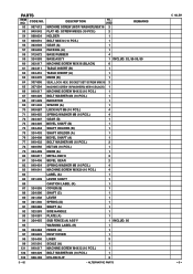
PARTS ITEM NO. CODE NO. 259 620-1VV DESCRIPTION BALL BEARING 6201VVCMPS2L NO. SCREW M4X10 (10 PCS.) ... BEARING 608VVC2NS7L 1 307 324-443 PULLEY (A) 1 308 961-157 SUPER LOCK WASHER 1 309 949-560 NUT M10 (10 PCS.) 1 --- 8 --- * ALTERNATIVE PARTS C 12LSH 5 -- 05 USED 1 REMARKS 260 324-426 MONITOR 1 261 305-490 TAPPING SCREW (W/FLANGE) D4X30 (BLACK) 2 262 976-706 MACHINE SCREW (W/WASHERS...MACHINE SCREW (W/WASHERS) M4X12 (BLACK) 1 284 988-101 BOLT (A) M10 1 285 323-652 WASHER (B) 1 286 TCT SAW BLADE 305MM-D25.4 HOLE-NT60 1 287 324-452 WASHER (A) 1 288 949-322 FLAT HD.
PARTS ITEM NO. CODE NO. 259 620-1VV DESCRIPTION BALL BEARING 6201VVCMPS2L NO. SCREW M4X10 (10 PCS.) ... BEARING 608VVC2NS7L 1 307 324-443 PULLEY (A) 1 308 961-157 SUPER LOCK WASHER 1 309 949-560 NUT M10 (10 PCS.) 1 --- 8 --- * ALTERNATIVE PARTS C 12LSH 5 -- 05 USED 1 REMARKS 260 324-426 MONITOR 1 261 305-490 TAPPING SCREW (W/FLANGE) D4X30 (BLACK) 2 262 976-706 MACHINE SCREW (W/WASHERS...MACHINE SCREW (W/WASHERS) M4X12 (BLACK) 1 284 988-101 BOLT (A) M10 1 285 323-652 WASHER (B) 1 286 TCT SAW BLADE 305MM-D25.4 HOLE-NT60 1 287 324-452 WASHER (A) 1 288 949-322 FLAT HD.

Parts List
Page 9
USED 310 324-427 BELT (200H13) 16X508 1 311 983-545 NEEDLE ROLLER 2 312 322-303 BEARING HOLDER (B) 1 313 995-096 MACHINE SCREW (W/WASHERS) M5X20 (BLACK) 2 314 307-732 STOPPER PIN 1 315 949-429 BOLT WASHER M4 (10 PCS.) 1 316 949-215 MACHINE SCREW M4X8 (10 PCS.) 1 317 324-450 PULLEY COVER 1 REMARKS C 12LSH 5 -- 05 * ALTERNATIVE PARTS --- 9 --- CODE NO. PARTS ITEM NO. DESCRIPTION NO.
USED 310 324-427 BELT (200H13) 16X508 1 311 983-545 NEEDLE ROLLER 2 312 322-303 BEARING HOLDER (B) 1 313 995-096 MACHINE SCREW (W/WASHERS) M5X20 (BLACK) 2 314 307-732 STOPPER PIN 1 315 949-429 BOLT WASHER M4 (10 PCS.) 1 316 949-215 MACHINE SCREW M4X8 (10 PCS.) 1 317 324-450 PULLEY COVER 1 REMARKS C 12LSH 5 -- 05 * ALTERNATIVE PARTS --- 9 --- CODE NO. PARTS ITEM NO. DESCRIPTION NO.

Parts List
Page 10
... CROWN MOLDING VISE ASS'Y 1 INCLUD. 605, 626 628 305-546 TCT SAW BLADE 305MM-D25.4 HOLE-NT60 1 629 309-418 TCT SAW BLADE 305MM-D25.4 HOLE-NT80 1 630 301-721 TCT SAW BLADE 305MM-D25.4 HOLE-NT90 1 631 310-875 TCT SAW BLADE 305MM-D25.4 HOLE-NT96 1 --- 10 --- * ALTERNATIVE PARTS Printed in Japan 5-- 05 (050520N)
... CROWN MOLDING VISE ASS'Y 1 INCLUD. 605, 626 628 305-546 TCT SAW BLADE 305MM-D25.4 HOLE-NT60 1 629 309-418 TCT SAW BLADE 305MM-D25.4 HOLE-NT80 1 630 301-721 TCT SAW BLADE 305MM-D25.4 HOLE-NT90 1 631 310-875 TCT SAW BLADE 305MM-D25.4 HOLE-NT96 1 --- 10 --- * ALTERNATIVE PARTS Printed in Japan 5-- 05 (050520N)


