
Instruction Manual
Page 4
... never expose it was not designed. 8. ALWAYS USE THE RIGHT TOOLS. ALWAYS SECURE THE WORKPIECE TO THE FENCE OR THE TABLE. ALWAYS REMOVE ADJUSTING KEYS AND WRENCHES BEFORE STARTING TOOL. Always wear non-slip footwear, preferably with the tool. 4 ALWAYS USE EYE PROTECTION WHEN WORKING WITH THE ...which it to minimize the risk of safety glass. Avoid injuries by installing locks on the doors and on . 3. Keep all keys and adjusting wrenches have been removed from the work place tamper-proof by not cluttering the work areas and work area well lighted. 5. Ordinary eyeglasses ...
... never expose it was not designed. 8. ALWAYS USE THE RIGHT TOOLS. ALWAYS SECURE THE WORKPIECE TO THE FENCE OR THE TABLE. ALWAYS REMOVE ADJUSTING KEYS AND WRENCHES BEFORE STARTING TOOL. Always wear non-slip footwear, preferably with the tool. 4 ALWAYS USE EYE PROTECTION WHEN WORKING WITH THE ...which it to minimize the risk of safety glass. Avoid injuries by installing locks on the doors and on . 3. Keep all keys and adjusting wrenches have been removed from the work place tamper-proof by not cluttering the work areas and work area well lighted. 5. Ordinary eyeglasses ...

Instruction Manual
Page 6
...saw at once, if you notice any maintenance or adjustments. 9. The operating instructions provided with the safety rules and operating instructions for the saw...miter or bevel cutting, always wait for use it . 3. Always confirm that the motor air vents are mounted properly and securely before attempting slide...of the path of the slide compound miter saw blade. 16. Always make a trial run first before using the saw . 13. Always operate ...the POWER TOOL carefully. During slide cutting, always push the saw blade. 12. Always handle the saw blade with care when dismounting and...
...saw at once, if you notice any maintenance or adjustments. 9. The operating instructions provided with the safety rules and operating instructions for the saw...miter or bevel cutting, always wait for use it . 3. Always confirm that the motor air vents are mounted properly and securely before attempting slide...of the path of the slide compound miter saw blade. 16. Always make a trial run first before using the saw . 13. Always operate ...the POWER TOOL carefully. During slide cutting, always push the saw blade. 12. Always handle the saw blade with care when dismounting and...

Instruction Manual
Page 14
For example, use 2-9/16" (65 mm) or larger bolts for the thickness of the work bench. Adjust the holder until its bottom surface contacts the work bench. Fig. 5 14 PREPARATION BEFORE OPERATION Make the following preparations before operating the..., horizontal work bench in length for a 1" (25 mm) thick work bench surface. After adjustment, firmly tighten the 6 6 mm mm bolt Bolt Move Holder Adjust the holder until its bottom surface contacts the work bench. a7c ---1/ Holder adjustment: Loosen the 6 mm bolt with Fig. 4. English APPLICATIONS Wood and aluminum sash.
For example, use 2-9/16" (65 mm) or larger bolts for the thickness of the work bench. Adjust the holder until its bottom surface contacts the work bench. Fig. 5 14 PREPARATION BEFORE OPERATION Make the following preparations before operating the..., horizontal work bench in length for a 1" (25 mm) thick work bench surface. After adjustment, firmly tighten the 6 6 mm mm bolt Bolt Move Holder Adjust the holder until its bottom surface contacts the work bench. a7c ---1/ Holder adjustment: Loosen the 6 mm bolt with Fig. 4. English APPLICATIONS Wood and aluminum sash.
Instruction Manual
Page 16
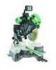
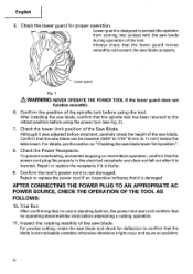
.... Although it is inserted. Check the Power Receptacle. Repair or replace the receptacle if it was adjusted before using the power tool (see the section on "Checking the saw blade, confirm that the spindle lock has been returned to confirm that no one is damaged AFTER CONNECTING THE POWER PLUG TO AN...retract position before attempting a cutting operation. 11. Lower guard is designed to 11 mm) below the table insert. English 5. Trial Run After confirming that the saw blade can be lowered 23/64" to 7/16" (9 mm to protect the operator from coming into contact with the...
.... Although it is inserted. Check the Power Receptacle. Repair or replace the receptacle if it was adjusted before using the power tool (see the section on "Checking the saw blade, confirm that the spindle lock has been returned to confirm that no one is damaged AFTER CONNECTING THE POWER PLUG TO AN...retract position before attempting a cutting operation. 11. Lower guard is designed to 11 mm) below the table insert. English 5. Trial Run After confirming that the saw blade can be lowered 23/64" to 7/16" (9 mm to protect the operator from coming into contact with the...
Instruction Manual
Page 17
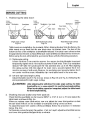
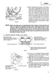
... reduced, if the table insert is fixed so that serves as shown in Fig. 9-a. When bevel cutting operation is used for bevel angle cutting. 2. To adjust the lower limit position of the saw blade, follow the procedure (1) indicated below the table insert as a lower limit position stopper of... the table insert and the saw blade can be cut it is required, adjust the table insert for bevel angle cutting. When shipping the tool from the factory, the table inserts are installed on the turntable. Then...
... reduced, if the table insert is fixed so that serves as shown in Fig. 9-a. When bevel cutting operation is used for bevel angle cutting. 2. To adjust the lower limit position of the saw blade, follow the procedure (1) indicated below the table insert as a lower limit position stopper of... the table insert and the saw blade can be cut it is required, adjust the table insert for bevel angle cutting. When shipping the tool from the factory, the table inserts are installed on the turntable. Then...
Instruction Manual
Page 18
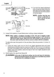
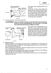
Lower limit position of saw blade when cutting a large workpiece NOTE: When cutting a workpiece exceeding 4-7/32" (107 mm) in height in rightangle cutting or 2-3/4"(70 mm) in left bevel angle cutting or 1-3/4" (45 mm) in right bevel angle cutting, adjust the lower limit position so that the base of the motor...Fig. 9-a) will not cut into the turntable. Confirmation for use of sub fence (A) & WARNING: In the case of right bevel cutting, turn the 8 mm depth adjustment bolt and make adjustments so that there can be a clearance of 5/64" to 1/8" (2 mm to 3 mm) between the lower limit position of...
Lower limit position of saw blade when cutting a large workpiece NOTE: When cutting a workpiece exceeding 4-7/32" (107 mm) in height in rightangle cutting or 2-3/4"(70 mm) in left bevel angle cutting or 1-3/4" (45 mm) in right bevel angle cutting, adjust the lower limit position so that the base of the motor...Fig. 9-a) will not cut into the turntable. Confirmation for use of sub fence (A) & WARNING: In the case of right bevel cutting, turn the 8 mm depth adjustment bolt and make adjustments so that there can be a clearance of 5/64" to 1/8" (2 mm to 3 mm) between the lower limit position of...
Instruction Manual
Page 19
... 8 mm set pin (A) on the direction shown in Fig. 12-b and incline the motor head to its initial position as shown in Fig. 12-b. 19 Sub fence (B) Fence (B) Fig. 11 6. When changing the adjustment, change the height of right bevel cutting, raise the sub fence (A) up as illustrated in Fig.... 10 and then turn it is turned counterclockwise, the main body or saw blade may contact the sub fence...
... 8 mm set pin (A) on the direction shown in Fig. 12-b and incline the motor head to its initial position as shown in Fig. 12-b. 19 Sub fence (B) Fence (B) Fig. 11 6. When changing the adjustment, change the height of right bevel cutting, raise the sub fence (A) up as illustrated in Fig.... 10 and then turn it is turned counterclockwise, the main body or saw blade may contact the sub fence...
Instruction Manual
Page 20
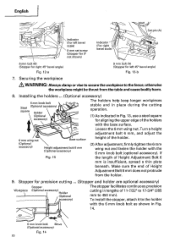
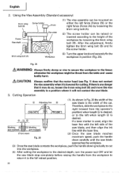
... mm to the holder with the 6 mm knob bolt as shown in Fig. 13, use a steel square for aligning the upper edge of Height Adjustment Bolt 6 mm is insufficient, spread a thin plate beneath. To install the stopper, attach it to 450 mm). Securing the workpiece WARNING: Always clamp... or vise to secure the workpiece to the fence; Loosen the 6 mm wing nut. English O Set pin (A) Indicator (For left 45° bevel angle) Fig. 12-b 7. If Fig. 13 the length of the holders with the 6 mm knob bolt (optional accessory). otherwise the workpiece might be thrust from the holder....
... mm to the holder with the 6 mm knob bolt as shown in Fig. 13, use a steel square for aligning the upper edge of Height Adjustment Bolt 6 mm is insufficient, spread a thin plate beneath. To install the stopper, attach it to 450 mm). Securing the workpiece WARNING: Always clamp... or vise to secure the workpiece to the fence; Loosen the 6 mm wing nut. English O Set pin (A) Indicator (For left 45° bevel angle) Fig. 12-b 7. If Fig. 13 the length of the holders with the 6 mm knob bolt (optional accessory). otherwise the workpiece might be thrust from the holder....
Instruction Manual
Page 21
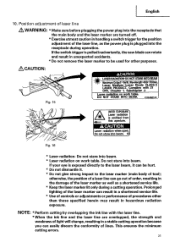
... is emitted from this aperture. DO NOT STARE INTO BEAM. 0324601© Fig. 15 0 A AVOID EXPOSURE Laser radiation is pulledinadvertently,the saw blade can rotate and result in unexpected accidents. * Do not remove the laser marker to the laser marker (main body of laser line ... the receptacle during a cutting operation. otherwise,the position of a laser line can result in a shortened service life. * Use of controls or adjustments or performance of the laser line, as a shortened service life. * Keep the laser marker lit only during operation. Complies with the laser line...
... is emitted from this aperture. DO NOT STARE INTO BEAM. 0324601© Fig. 15 0 A AVOID EXPOSURE Laser radiation is pulledinadvertently,the saw blade can rotate and result in unexpected accidents. * Do not remove the laser marker to the laser marker (main body of laser line ... the receptacle during a cutting operation. otherwise,the position of a laser line can result in a shortened service life. * Use of controls or adjustments or performance of the laser line, as a shortened service life. * Keep the laser marker lit only during operation. Complies with the laser line...
Instruction Manual
Page 22
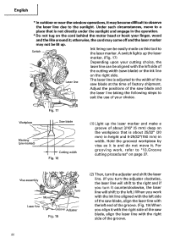
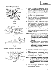
.../32" (20 mm) in height and 5-29/32"(150 mm) in the operation. * Do not tug on this tool to the laser marker. Adjust the positions of the saw blade and the laser line taking the following steps to suit the use of your cutting choice, the laser line can be aligned... cutting procedures" on page 37. Hold the grooved workpiece by vise as it with the right side of the saw blade, align the laser line with the left .) When you turn the adjuster clockwise, the laser line will shift to the right and if you work , refer to a place that is not...
.../32" (20 mm) in height and 5-29/32"(150 mm) in the operation. * Do not tug on this tool to the laser marker. Adjust the positions of the saw blade and the laser line taking the following steps to suit the use of your cutting choice, the laser line can be aligned... cutting procedures" on page 37. Hold the grooved workpiece by vise as it with the right side of the saw blade, align the laser line with the left .) When you turn the adjuster clockwise, the laser line will shift to the right and if you work , refer to a place that is not...
Instruction Manual
Page 23
...that turntable is rotating. When aligning the ink line, slide the workpiece little by little and secure it by vise at least 0.2 second. Work on , lights up Digital display switch Laser marker switch (for C12LSH) Miter angle window (Displays arrows show angle and direction that ...to (3). Left is .) Bevel angle window (Displays arrows showing motor head bevel angle and bevel direction. English ~\ Laser line Marking (pre-marked Fig. 20 (3) After adjusting the position of main unit angle. (2) Align the main unit angle with the tilt angle (01 and miter angle (0°) and hold...
...that turntable is rotating. When aligning the ink line, slide the workpiece little by little and secure it by vise at least 0.2 second. Work on , lights up Digital display switch Laser marker switch (for C12LSH) Miter angle window (Displays arrows show angle and direction that ...to (3). Left is .) Bevel angle window (Displays arrows showing motor head bevel angle and bevel direction. English ~\ Laser line Marking (pre-marked Fig. 20 (3) After adjusting the position of main unit angle. (2) Align the main unit angle with the tilt angle (01 and miter angle (0°) and hold...
Instruction Manual
Page 26
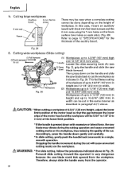
... fix the screw holder. 6mm wing bolt (A) Workpiece (3) Turn the upper knob and securely fix the workpiece in Fig. 26 the width of the Adjusting line saw blade is the width of the cut into the workpiece. (4) After cutting the workpiece to the desired depth, turn the power tool OFF and let.... 25 &WARNING: Always firmly clamp or vise to secure the workpiece to the left side of the workpiece by loosening the 6mm wing bolt (B). Therefore, slide the workpiece to the right (viewed from the table and cause bodily harm. &CAUTION: Always confirm that the motor head (see Fig. 1) does not ...
... fix the screw holder. 6mm wing bolt (A) Workpiece (3) Turn the upper knob and securely fix the workpiece in Fig. 26 the width of the Adjusting line saw blade is the width of the cut into the workpiece. (4) After cutting the workpiece to the desired depth, turn the power tool OFF and let.... 25 &WARNING: Always firmly clamp or vise to secure the workpiece to the left side of the workpiece by loosening the 6mm wing bolt (B). Therefore, slide the workpiece to the right (viewed from the table and cause bodily harm. &CAUTION: Always confirm that the motor head (see Fig. 1) does not ...
Instruction Manual
Page 28
...cutting of workpieces of up to 4-3/16" (107 mm) high and 12-1/4" (312 mm) wide: Handle Loosen the slide securing knob (A) (see t C) Press Fig. 2), grip the handle and slide the saw * down on the handle and slide the saw blade may be case when a complete cutting cannot be done depending on... each side). (Fig. 28) Refer to 4-3/16" (107 mm) in Workpiece height and 12-1/4" (312 mm) in Fig. 29. A CAUTION: *When cutting a workpiece of 4-3/4" (120 mm) height, adjust...
...cutting of workpieces of up to 4-3/16" (107 mm) high and 12-1/4" (312 mm) wide: Handle Loosen the slide securing knob (A) (see t C) Press Fig. 2), grip the handle and slide the saw * down on the handle and slide the saw blade may be case when a complete cutting cannot be done depending on... each side). (Fig. 28) Refer to 4-3/16" (107 mm) in Workpiece height and 12-1/4" (312 mm) in Fig. 29. A CAUTION: *When cutting a workpiece of 4-3/4" (120 mm) height, adjust...
Instruction Manual
Page 29
... set pin (A) towards the rear. If the handle is raised while the saw blade is still rotating, the cut -off portion will be caught in the right 45° bevel cutting position, adjust the lower limit position of the motor head so that the gap between the...for right scale bevel scale) Fig. 30 (1) Loosen the clamp lever and bevel the saw blade lower limit position" on page 12. Bevel cutting procedures Clamp Lever M 0 Holder (A) Pull 4r-lZ Indicator Bevel Set pin (A) (for bevel cutting, refer to the right. Checking the saw blade to the left 45° bevel cutting position ...
... set pin (A) towards the rear. If the handle is raised while the saw blade is still rotating, the cut -off portion will be caught in the right 45° bevel cutting position, adjust the lower limit position of the motor head so that the gap between the...for right scale bevel scale) Fig. 30 (1) Loosen the clamp lever and bevel the saw blade lower limit position" on page 12. Bevel cutting procedures Clamp Lever M 0 Holder (A) Pull 4r-lZ Indicator Bevel Set pin (A) (for bevel cutting, refer to the right. Checking the saw blade to the left 45° bevel cutting position ...

Instruction Manual
Page 30
..., tighten the clamp lever and clamp the motor head. & CAUTION: Always check that the clamp lever is secured and the motor head is clamped. Bevel angle fine adjustment Handle Loosen Tighten Clamp lever Clamp lever Knob (B) I Knob (B) 8 mm bolt (B) Fig. 31 H Fig. 32 (1) Grip the handle on the ...motor head and position it will not move or slip, causing injuries. Turning knob (B) counterclockwise, allows fine adjustment of the bevel angle, turn the knob (B) while supporting the handle with your hand. Be sure to tighten the motor head section enough so it at the...
..., tighten the clamp lever and clamp the motor head. & CAUTION: Always check that the clamp lever is secured and the motor head is clamped. Bevel angle fine adjustment Handle Loosen Tighten Clamp lever Clamp lever Knob (B) I Knob (B) 8 mm bolt (B) Fig. 31 H Fig. 32 (1) Grip the handle on the ...motor head and position it will not move or slip, causing injuries. Turning knob (B) counterclockwise, allows fine adjustment of the bevel angle, turn the knob (B) while supporting the handle with your hand. Be sure to tighten the motor head section enough so it at the...
Instruction Manual
Page 31
...Positive stops are properly aligned. * Operation of the saw with the miter scale and indicator out of the cutting angle, if desired (see Fig. 34). Knob (Al NOTE: Turning knob (A) clockwise, allows fine Turntable 0 0 0 0 Side handle adjustment of 2/10, set the indicator to cut a workpiece... at 15°, 22.5°, 31.6° and 45° settings. b0 0 Grade scale -ob 1"I A0 O 12/ 1O j 0 3/1 1225 Miter scale Fig. 34 M 10 Fig. 35 (5) Therefore, to ...
...Positive stops are properly aligned. * Operation of the saw with the miter scale and indicator out of the cutting angle, if desired (see Fig. 34). Knob (Al NOTE: Turning knob (A) clockwise, allows fine Turntable 0 0 0 0 Side handle adjustment of 2/10, set the indicator to cut a workpiece... at 15°, 22.5°, 31.6° and 45° settings. b0 0 Grade scale -ob 1"I A0 O 12/ 1O j 0 3/1 1225 Miter scale Fig. 34 M 10 Fig. 35 (5) Therefore, to ...
Instruction Manual
Page 32
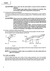
... causing injuries. 11. Compound cutting procedures Compound cutting can be performed by sliding the round portion of the indicator before the operation starts. 32 For maximum dimensions for compound cutting, refer to properly align the miter angle scale and the tip of the saw blade may come into ... In case of the angles described, move the turntable adjusting side handle a little to the right and left to stabilize the position and to "SPECIFICATIONS" table on page 12. &CAUTION: Always secure the workpiece with the left bevel, turn the sub-fence (A) clockwise, and engage in...
... causing injuries. 11. Compound cutting procedures Compound cutting can be performed by sliding the round portion of the indicator before the operation starts. 32 For maximum dimensions for compound cutting, refer to properly align the miter angle scale and the tip of the saw blade may come into ... In case of the angles described, move the turntable adjusting side handle a little to the right and left to stabilize the position and to "SPECIFICATIONS" table on page 12. &CAUTION: Always secure the workpiece with the left bevel, turn the sub-fence (A) clockwise, and engage in...
Instruction Manual
Page 36
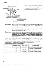
...saw blade. Adjust the crown molding Stoppers according to the size of blade 36 otherwise the crown molding might be thrust from the table and cause bodily harm. English Crown molding vise ass'y (Optional accessories) 6mm knob bolt Knob After adjusting... as necessary, to securely attach the crown molding in Fig. 47-b. Do not bevel cutting. If there is any danger that it may contact the sub fence, resulting...molding. Tighten the 6mm wing bolt to a position where it is lowered for the miter angle. Position in an injury. &CAUTION: Always confirm that the motor head (see...
...saw blade. Adjust the crown molding Stoppers according to the size of blade 36 otherwise the crown molding might be thrust from the table and cause bodily harm. English Crown molding vise ass'y (Optional accessories) 6mm knob bolt Knob After adjusting... as necessary, to securely attach the crown molding in Fig. 47-b. Do not bevel cutting. If there is any danger that it may contact the sub fence, resulting...molding. Tighten the 6mm wing bolt to a position where it is lowered for the miter angle. Position in an injury. &CAUTION: Always confirm that the motor head (see...

Instruction Manual
Page 37
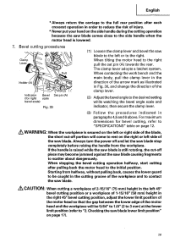
... • English O Fig. 48 Fig. 49 Bottom line Turntable of the turntable (see b in Fig. 48 by adjusting the 6 mm depth adjustment bolt. When cutting aluminum materials, coat the saw blade and the surface of the groove Grooves in the workpiece can be cut as aluminum sash can easily deform... in Fig. 50-b to achieve smooth cutting and a fine finish. Lower the motor head, and turn the 6 mm depth adjustment bolt by setting the distance between the saw blade with cutting oil (non-combustible) to ensure stability in the lateral direction, and clamp it near the cutting section. Set...
... • English O Fig. 48 Fig. 49 Bottom line Turntable of the turntable (see b in Fig. 48 by adjusting the 6 mm depth adjustment bolt. When cutting aluminum materials, coat the saw blade and the surface of the groove Grooves in the workpiece can be cut as aluminum sash can easily deform... in Fig. 50-b to achieve smooth cutting and a fine finish. Lower the motor head, and turn the 6 mm depth adjustment bolt by setting the distance between the saw blade with cutting oil (non-combustible) to ensure stability in the lateral direction, and clamp it near the cutting section. Set...

Parts List
Page 7
... MACHINE SCREW M5X12 (10 PCS.) 1 189 303-854 SPACER 1 190 324-376 LINK 1 191 319-270 ADJUSTER 1 192 973-313 NYLON CLIP 1 193 305-180 CLUTCH SCREW 1 194 305-179 CLUTCH SPRING 1 195 962-614 ADJUSTING WASHER (B) T0.5 1 196 319-268 PLATE (B) 1 197 305-179 CLUTCH SPRING 1 198 321-348 LASER MARKER...
... MACHINE SCREW M5X12 (10 PCS.) 1 189 303-854 SPACER 1 190 324-376 LINK 1 191 319-270 ADJUSTER 1 192 973-313 NYLON CLIP 1 193 305-180 CLUTCH SCREW 1 194 305-179 CLUTCH SPRING 1 195 962-614 ADJUSTING WASHER (B) T0.5 1 196 319-268 PLATE (B) 1 197 305-179 CLUTCH SPRING 1 198 321-348 LASER MARKER...


