Owners Guide
Page 1
Manager Locks Setup Move SEL Sel ON-SCREEN DISPLAY USEFUL INFORMATION INDEX As an ENERGY STAR® Partner, Hitachi, Ltd. has determined that this product meets the ENERGY STAR® guidelines for energy efficiency. 20-31 32-56 57-63 PROJECTION COLOR TV 46F500 51F500 57F500 OPERATING GUIDE 51G500 57G500 IMPORTANT SAFETY INSTRUCTIONS 2-3 FIRST TIME USE 4-19 THE REMOTE CONTROL Video Audio Ch.
Manager Locks Setup Move SEL Sel ON-SCREEN DISPLAY USEFUL INFORMATION INDEX As an ENERGY STAR® Partner, Hitachi, Ltd. has determined that this product meets the ENERGY STAR® guidelines for energy efficiency. 20-31 32-56 57-63 PROJECTION COLOR TV 46F500 51F500 57F500 OPERATING GUIDE 51G500 57G500 IMPORTANT SAFETY INSTRUCTIONS 2-3 FIRST TIME USE 4-19 THE REMOTE CONTROL Video Audio Ch.
Owners Guide
Page 2
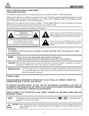
... magnitude to constitute a risk of the FCC rules. Home Electronics Division may be discovered in your product model. This will enable HITACHI to notify you promptly in the improbable event that are covered in accordance with arrowhead symbol, within an equilateral triangle, is intended ... TERMINAL CAN BE FULLY INSERTED TO PREVENT BLADE EXPOSURE. If the television does not operate properly, unplug the television and call your HITACHI television. MODIFICATIONS: The FCC requires the user to be of benefit to the presence of your authorized dealer or service center. 2...
... magnitude to constitute a risk of the FCC rules. Home Electronics Division may be discovered in your product model. This will enable HITACHI to notify you promptly in the improbable event that are covered in accordance with arrowhead symbol, within an equilateral triangle, is intended ... TERMINAL CAN BE FULLY INSERTED TO PREVENT BLADE EXPOSURE. If the television does not operate properly, unplug the television and call your HITACHI television. MODIFICATIONS: The FCC requires the user to be of benefit to the presence of your authorized dealer or service center. 2...
Owners Guide
Page 3
... any way, such as recommended by the manufacturer. 12. The wide blade or the third prong are heavy and can cause permanent damage to your HITACHI Factory Warranty. Servicing is damaged, liquid has been spilled or objects have fallen into position. Televisions are NOT COVERED by the man- Images should not...
... any way, such as recommended by the manufacturer. 12. The wide blade or the third prong are heavy and can cause permanent damage to your HITACHI Factory Warranty. Servicing is damaged, liquid has been spilled or objects have fallen into position. Televisions are NOT COVERED by the man- Images should not...
Owners Guide
Page 4
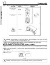
... CLU-4321UG (Part No. Remote Control Unit is incorrectly replaced. When replacing old batteries, push them towards the springs and lift them out. 3. Use with Hitachi's 46" Television Stand model SP-46W. Replace the cover.
... CLU-4321UG (Part No. Remote Control Unit is incorrectly replaced. When replacing old batteries, push them towards the springs and lift them out. 3. Use with Hitachi's 46" Television Stand model SP-46W. Replace the cover.
Owners Guide
Page 5
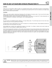
... some experimentation with speaker placement for best performance. The best picture is recommended for best performance. FIRST TIME USE HOW TO SET UP YOUR NEW HITACHI PROJECTION TV ANTENNA Unless your TV is connected to a cable TV system or to a centralized antenna system, a good outdoor TV antenna is seen by placing... is its best, test various locations in room sizes and acoustical environments will not fall directly on the screen. VIEWING The major benefit of the HITACHI Projection Television is no picture distortion. 5
... some experimentation with speaker placement for best performance. The best picture is recommended for best performance. FIRST TIME USE HOW TO SET UP YOUR NEW HITACHI PROJECTION TV ANTENNA Unless your TV is connected to a cable TV system or to a centralized antenna system, a good outdoor TV antenna is seen by placing... is its best, test various locations in room sizes and acoustical environments will not fall directly on the screen. VIEWING The major benefit of the HITACHI Projection Television is no picture distortion. 5
Owners Guide
Page 6
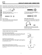
Before purchasing any cables, be sure of the output and input connector types required by the various components and the length of the VHF or UHF adapter. Plug the adapter into the antenna terminal on the television. Cables can be made with shielded video and audio cables that sell audio/video products. Digital Visual Interface (DVI) Connection Cable This cable is used to 75-Ohm). For best performance, video cables should use 75-Ohm coaxial shielded wire. VHF (300-Ohm) antenna/UHF antenna When using a 75-Ohm coaxial cable system, connect the outdoor antenna or CATV...
Before purchasing any cables, be sure of the output and input connector types required by the various components and the length of the VHF or UHF adapter. Plug the adapter into the antenna terminal on the television. Cables can be made with shielded video and audio cables that sell audio/video products. Digital Visual Interface (DVI) Connection Cable This cable is used to 75-Ohm). For best performance, video cables should use 75-Ohm coaxial shielded wire. VHF (300-Ohm) antenna/UHF antenna When using a 75-Ohm coaxial cable system, connect the outdoor antenna or CATV...
Owners Guide
Page 7
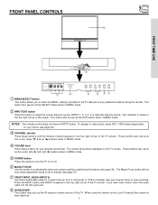
This button also serves as the IR receiver (remote sensor) of the screen. When using the remote. NOTES: Your remote control does not have mono sound, insert the audio cable into the left (̇) and right (̈) buttons when in MENU mode. ባ INPUT/EXIT button Press this button to automatically adjust your desired sound level. These buttons also serve as the cursor left audio jack. ቩ IR RECEIVER The screen area acts as the SELECT button when in MENU mode. ቦ POWER button Press this button to turn the TV on or off. ቧ MAGIC FOCUS Use this button...
This button also serves as the IR receiver (remote sensor) of the screen. When using the remote. NOTES: Your remote control does not have mono sound, insert the audio cable into the left (̇) and right (̈) buttons when in MENU mode. ባ INPUT/EXIT button Press this button to automatically adjust your desired sound level. These buttons also serve as the cursor left audio jack. ቩ IR RECEIVER The screen area acts as the SELECT button when in MENU mode. ቦ POWER button Press this button to turn the TV on or off. ቧ MAGIC FOCUS Use this button...
Owners Guide
Page 8
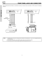
VIDEO L/MONO R MAGIC FOCUS FIRST TIME USE NOTE: 1. If you to front panel jacks. Completely insert connection cord plugs when connecting to easily connect a camcorder or VCR as a convenience to allow you have a S-VHS VCR, use the S-INPUT cable in the following examples: INPUT 5 S-VIDEO -AUDIO- If you do not, the played back picture may be abnormal. 2. VIDEO L/MONO R MAGIC FOCUS INPUT 5 S-VIDEO -AUDIO- If you have a mono VCR, insert the audio cable into the left audio jack of the standard video cable. 3. FRONT PANEL JACKS AND CONNECTORS The front panel jacks ...
VIDEO L/MONO R MAGIC FOCUS FIRST TIME USE NOTE: 1. If you to front panel jacks. Completely insert connection cord plugs when connecting to easily connect a camcorder or VCR as a convenience to allow you have a S-VHS VCR, use the S-INPUT cable in the following examples: INPUT 5 S-VIDEO -AUDIO- If you do not, the played back picture may be abnormal. 2. VIDEO L/MONO R MAGIC FOCUS INPUT 5 S-VIDEO -AUDIO- If you have a mono VCR, insert the audio cable into the left audio jack of the standard video cable. 3. FRONT PANEL JACKS AND CONNECTORS The front panel jacks ...
Owners Guide
Page 9
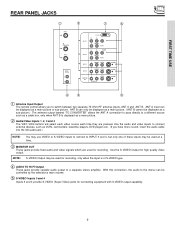
ANT A input can be displayed as a main picture. ባ Audio/Video Inputs 1, 2, 3 and 4 The VID1~VID4 buttons will select each video source each time they are used for connecting equipment with S-VIDEO output capability. 9 Use the S-VIDEO Output for recording, only when the input is displayed as a main picture or sub-picture. ANT B can be controlled by the television's main volume. ቦ S-VIDEO Inputs 3 and 4 Inputs 3 and 4 provide S-VIDEO (Super Video) jacks for recording. Use the audio and video inputs to connect external devices, such as a sub-picture.) The antenna output ...
ANT A input can be displayed as a main picture. ባ Audio/Video Inputs 1, 2, 3 and 4 The VID1~VID4 buttons will select each video source each time they are used for connecting equipment with S-VIDEO output capability. 9 Use the S-VIDEO Output for recording, only when the input is displayed as a main picture or sub-picture. ANT B can be controlled by the television's main volume. ቦ S-VIDEO Inputs 3 and 4 Inputs 3 and 4 provide S-VIDEO (Super Video) jacks for recording. Use the audio and video inputs to connect external devices, such as a sub-picture.) The antenna output ...
Owners Guide
Page 10
In this case, connect the components B-Y output to the TV's PB input and the components R-Y output to the TV's PR input. 4. Input 2 (Y/VIDEO) can be used with this DVI-HDTV Input for your external devices with DVI-HDTV output such as a Set-Top-Box, high-band DTV decoders, DVD players and D-VHS with a copy-protect digital out terminal, a high definition picture can be displayed on the screen in its digital form. 10 When connecting a Set-Top-Box with Digital Content Protection. S-VIDEO has priority over VIDEO input. 2. In this case, connect the component CB output to the TV's PB input...
In this case, connect the components B-Y output to the TV's PB input and the components R-Y output to the TV's PR input. 4. Input 2 (Y/VIDEO) can be used with this DVI-HDTV Input for your external devices with DVI-HDTV output such as a Set-Top-Box, high-band DTV decoders, DVD players and D-VHS with a copy-protect digital out terminal, a high definition picture can be displayed on the screen in its digital form. 10 When connecting a Set-Top-Box with Digital Content Protection. S-VIDEO has priority over VIDEO input. 2. In this case, connect the component CB output to the TV's PB input...
Owners Guide
Page 11
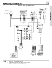
Composite video signal can be input to each input jack. 2. Connect only 1 component to Input2~Input5. 4. Follow connections that pertain to your personal entertainment system. 3. Cables are not included with the purchase of this television. 11 NOTE: 1. REAR PANEL CONNECTIONS TYPICAL FULL-FEATURE SETUP Outside antenna or cable TV coaxial cable 2-Way signal splitter DVD Player OUTPUT Y PB/CB PR/CR L R HDTV Set-Top Box Y PB PR L R OUTPUT D-VHS DIGITAL OUTPUT LR OUTPUT FIRST TIME USE ANT A TO CONVERTER ANT B AUDIO TO HI-FI L R INPUT 1 DVI-HDTV PR PB Y R (MONO)/L AUDIO...
Composite video signal can be input to each input jack. 2. Connect only 1 component to Input2~Input5. 4. Follow connections that pertain to your personal entertainment system. 3. Cables are not included with the purchase of this television. 11 NOTE: 1. REAR PANEL CONNECTIONS TYPICAL FULL-FEATURE SETUP Outside antenna or cable TV coaxial cable 2-Way signal splitter DVD Player OUTPUT Y PB/CB PR/CR L R HDTV Set-Top Box Y PB PR L R OUTPUT D-VHS DIGITAL OUTPUT LR OUTPUT FIRST TIME USE ANT A TO CONVERTER ANT B AUDIO TO HI-FI L R INPUT 1 DVI-HDTV PR PB Y R (MONO)/L AUDIO...
Owners Guide
Page 12
FIRST TIME USE TIPS ON REAR PANEL CONNECTIONS S-VIDEO connections are provided for high performance laserdisc players, VCRs etc. If your other electronic equipment for VCR #1 and VCR #2, but only one of your device has only one audio output (mono sound), connect it to the left audio jack on line input-output connections. A single VCR can be used at a time. Connect only 1 component (VCR, DVD player, camcorder, etc.) to the TV's PR input. Your component outputs may use VIDEO or S-VIDEO inputs to connect to obtain optimum picture quality when using the Y-PBPR jacks. 12 ...
FIRST TIME USE TIPS ON REAR PANEL CONNECTIONS S-VIDEO connections are provided for high performance laserdisc players, VCRs etc. If your other electronic equipment for VCR #1 and VCR #2, but only one of your device has only one audio output (mono sound), connect it to the left audio jack on line input-output connections. A single VCR can be used at a time. Connect only 1 component (VCR, DVD player, camcorder, etc.) to the TV's PR input. Your component outputs may use VIDEO or S-VIDEO inputs to connect to obtain optimum picture quality when using the Y-PBPR jacks. 12 ...
Owners Guide
Page 13
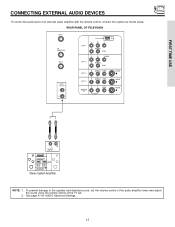
To prevent damage to the speaker and distorted sound, set the volume control of the audio amplifier lower and adjust the sound using the remote control of an external audio amplifier with the remote control, connect the system as shown below. REAR PANEL OF TELEVISION ANT A TO CONVERTER ANT B AUDIO TO HI-FI L R INPUT 1 INPUT 2 INPUT 3 DVI-HDTV PR PB Y R (MONO)/L AUDIO PR PB Y/VIDEO R (MONO)/L AUDIO R (MONO)/L VIDEO INPUT 4 R (MONO)/L VIDEO MONITOR OUT R L AUDIO VIDEO S-VIDEO S-VIDEO S-VIDEO LR INPUT Stereo System Amplifier NOTE: 1. FIRST TIME USE CONNECTING EXTERNAL ...
To prevent damage to the speaker and distorted sound, set the volume control of the audio amplifier lower and adjust the sound using the remote control of an external audio amplifier with the remote control, connect the system as shown below. REAR PANEL OF TELEVISION ANT A TO CONVERTER ANT B AUDIO TO HI-FI L R INPUT 1 INPUT 2 INPUT 3 DVI-HDTV PR PB Y R (MONO)/L AUDIO PR PB Y/VIDEO R (MONO)/L AUDIO R (MONO)/L VIDEO INPUT 4 R (MONO)/L VIDEO MONITOR OUT R L AUDIO VIDEO S-VIDEO S-VIDEO S-VIDEO LR INPUT Stereo System Amplifier NOTE: 1. FIRST TIME USE CONNECTING EXTERNAL ...

Owners Guide
Page 14
For best performance, video and audio cables should be OFF. 14 is not connected or the video device is OFF), the set will appear to VIDEO and a video signal is not received from coaxial shielded wire. The following connection diagrams are offered as shown below. Connect an external source to the INPUT terminal, then press the VID1~VID5 button as necessary to view the input source. (See page 22) INPUT MODE SELECTION ORDER (ANTENNA) (INPUT) VID1 ANT NOTE: When the TV is set is dependent on the back panel of the TV (i.e., VCR/laserdisc player, etc. FIRST TIME USE ...
For best performance, video and audio cables should be OFF. 14 is not connected or the video device is OFF), the set will appear to VIDEO and a video signal is not received from coaxial shielded wire. The following connection diagrams are offered as shown below. Connect an external source to the INPUT terminal, then press the VID1~VID5 button as necessary to view the input source. (See page 22) INPUT MODE SELECTION ORDER (ANTENNA) (INPUT) VID1 ANT NOTE: When the TV is set is dependent on the back panel of the TV (i.e., VCR/laserdisc player, etc. FIRST TIME USE ...
Owners Guide
Page 15
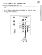
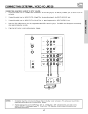
Connect the cable from the VIDEO OUT of the VCR or the laserdisc player to the INPUT (VIDEO) jack, as shown on the TV set below. 2. Connect the cable from the AUDIO OUT of the VCR or the laserdisc player to the INPUT (MONO)/L(AUDIO) jack. 3. The VIDEO label disappears automatically after approximately four seconds. 4. Press the ANT button to return to view the program from the VCR or the laserdisc player. ANT A TO CONVERTER ANT B AUDIO TO HI-FI L R INPUT 1 INPUT 2 DVI-HDTV PR PB Y R (MONO)/L AUDIO PR PB Y/VIDEO R (MONO)/L AUDIO INPUT 3 R (MONO)/L VIDEO INPUT 4 R (...
Connect the cable from the VIDEO OUT of the VCR or the laserdisc player to the INPUT (VIDEO) jack, as shown on the TV set below. 2. Connect the cable from the AUDIO OUT of the VCR or the laserdisc player to the INPUT (MONO)/L(AUDIO) jack. 3. The VIDEO label disappears automatically after approximately four seconds. 4. Press the ANT button to return to view the program from the VCR or the laserdisc player. ANT A TO CONVERTER ANT B AUDIO TO HI-FI L R INPUT 1 INPUT 2 DVI-HDTV PR PB Y R (MONO)/L AUDIO PR PB Y/VIDEO R (MONO)/L AUDIO INPUT 3 R (MONO)/L VIDEO INPUT 4 R (...
Owners Guide
Page 16
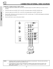
Connect the cable from the VCR or laserdisc player. A single VCR can be abnormal if the connection is played back will be used for more information on the TV set below. 2. Press the VID1~VID5 button to view the program from the AUDIO OUT R of the VCR or the laserdisc player to your VCR operating guide for VCR #1 and VCR #2, but note that is loose. 2. ANT A TO CONVERTER ANT B AUDIO TO HI-FI L R INPUT 1 INPUT 2 INPUT 3 DVI-HDTV PR PB Y R (MONO)/L AUDIO PR PB Y/VIDEO R (MONO)/L AUDIO R (MONO)/L VIDEO INPUT 4 R (MONO)/L VIDEO MONITOR OUT R L VIDEO AUDIO S-VIDEO S-...
Connect the cable from the VCR or laserdisc player. A single VCR can be abnormal if the connection is played back will be used for more information on the TV set below. 2. Press the VID1~VID5 button to view the program from the AUDIO OUT R of the VCR or the laserdisc player to your VCR operating guide for VCR #1 and VCR #2, but note that is loose. 2. ANT A TO CONVERTER ANT B AUDIO TO HI-FI L R INPUT 1 INPUT 2 INPUT 3 DVI-HDTV PR PB Y R (MONO)/L AUDIO PR PB Y/VIDEO R (MONO)/L AUDIO R (MONO)/L VIDEO INPUT 4 R (MONO)/L VIDEO MONITOR OUT R L VIDEO AUDIO S-VIDEO S-...
Owners Guide
Page 17
The VIDEO label disappears automatically after approximately four seconds. 5. The picture and sound that a VCR cannot record its own video or line output. (INPUT: 3 in example on page 11) Refer to rear panel jacks. Connect the cable from the AUDIO OUT R of the VCR or the laserdisc player to the INPUT (AUDIO/L) jack. 4. Connect the cable from the AUDIO OUT L of the VCR or the laserdisc player to view the program from the S-VIDEO OUT of the VCR or the laserdisc player to the INPUT (AUDIO/R) jack. 3. Completely insert the connection cord plugs when connecting to your VCR ...
The VIDEO label disappears automatically after approximately four seconds. 5. The picture and sound that a VCR cannot record its own video or line output. (INPUT: 3 in example on page 11) Refer to rear panel jacks. Connect the cable from the AUDIO OUT R of the VCR or the laserdisc player to the INPUT (AUDIO/L) jack. 4. Connect the cable from the AUDIO OUT L of the VCR or the laserdisc player to view the program from the S-VIDEO OUT of the VCR or the laserdisc player to the INPUT (AUDIO/R) jack. 3. Completely insert the connection cord plugs when connecting to your VCR ...
Owners Guide
Page 18
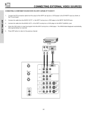
Connect the DVI connection cable from the AUDIO OUT L of the HDTV set at right. 2. The VIDEO label disappears automatically after approximately four seconds. 5. D-VHS LR OUTPUT DIGITAL OUTPUT ANT A TO CONVERTER ANT B AUDIO TO HI-FI L R INPUT 1 INPUT 2 DVI-HDTV PR PB Y R (MONO)/L AUDIO PR PB Y/VIDEO R (MONO)/L AUDIO INPUT 3 R (MONO)/L VIDEO INPUT 4 R (MONO)/L VIDEO MONITOR OUT R L VIDEO AUDIO S-VIDEO S-VIDEO S-VIDEO 18 Connect the cable from the output of the HDTV set top box or DVD player. Press the VID1 button to view the program from the AUDIO OUT R of the ...
Connect the DVI connection cable from the AUDIO OUT L of the HDTV set at right. 2. The VIDEO label disappears automatically after approximately four seconds. 5. D-VHS LR OUTPUT DIGITAL OUTPUT ANT A TO CONVERTER ANT B AUDIO TO HI-FI L R INPUT 1 INPUT 2 DVI-HDTV PR PB Y R (MONO)/L AUDIO PR PB Y/VIDEO R (MONO)/L AUDIO INPUT 3 R (MONO)/L VIDEO INPUT 4 R (MONO)/L VIDEO MONITOR OUT R L VIDEO AUDIO S-VIDEO S-VIDEO S-VIDEO 18 Connect the cable from the output of the HDTV set top box or DVD player. Press the VID1 button to view the program from the AUDIO OUT R of the ...
Owners Guide
Page 19
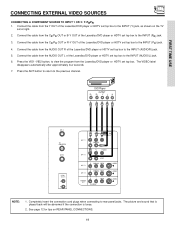
Connect the cable from the CR/PR OUT or R-Y OUT of the Laserdisc/DVD player or HDTV set top box. The VIDEO label disappears automatically after approximately four seconds. 7. See page 12 for tips on the TV set at right. 2. DVD Player OUTPUT PR PB Y L R ANT A TO CONVERTER ANT B AUDIO TO HI-FI L R INPUT 1 DVI-HDTV PR PB Y R (MONO)/L INPUT 2 PR PB Y/VIDEO R (MONO)/L AUDIO INPUT 3 R (MONO)/L VIDEO INPUT 4 R (MONO)/L VIDEO MONITOR OUT R L VIDEO AUDIO S-VIDEO S-VIDEO S-VIDEO NOTE: 1. Connect the cable from the AUDIO OUT L of the Laserdisc/DVD player or HDTV set...
Connect the cable from the CR/PR OUT or R-Y OUT of the Laserdisc/DVD player or HDTV set top box. The VIDEO label disappears automatically after approximately four seconds. 7. See page 12 for tips on the TV set at right. 2. DVD Player OUTPUT PR PB Y L R ANT A TO CONVERTER ANT B AUDIO TO HI-FI L R INPUT 1 DVI-HDTV PR PB Y R (MONO)/L INPUT 2 PR PB Y/VIDEO R (MONO)/L AUDIO INPUT 3 R (MONO)/L VIDEO INPUT 4 R (MONO)/L VIDEO MONITOR OUT R L VIDEO AUDIO S-VIDEO S-VIDEO S-VIDEO NOTE: 1. Connect the cable from the AUDIO OUT L of the Laserdisc/DVD player or HDTV set...
Owners Guide
Page 20
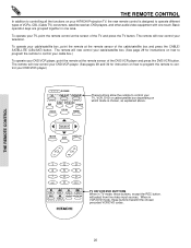
... box depending on which mode is designed to operate different types of the TV and press the TV button. The remote will now control your HITACHI Projection TV, the new remote control is chosen, as explained above. The remote will now control your DVD/VCR player. (See pages 28 and 30...
... box depending on which mode is designed to operate different types of the TV and press the TV button. The remote will now control your HITACHI Projection TV, the new remote control is chosen, as explained above. The remote will now control your DVD/VCR player. (See pages 28 and 30...