
Hardware Reference Guide
Page 5
... labels location ...3 2 Setup ...4 Installing the stand or approved VESA 100 mounting bracket 4 Securing the thin client ...6 Mounting and orienting the thin client ...7 Supported orientation and placement 8 Unsupported placement ...11 Connecting the power cord ...12 Routine thin client care ...12 3 Hardware changes ...13 Warnings and cautions ...13 Removing and replacing the access panel ...13...
... labels location ...3 2 Setup ...4 Installing the stand or approved VESA 100 mounting bracket 4 Securing the thin client ...6 Mounting and orienting the thin client ...7 Supported orientation and placement 8 Unsupported placement ...11 Connecting the power cord ...12 Routine thin client care ...12 3 Hardware changes ...13 Warnings and cautions ...13 Removing and replacing the access panel ...13...
Hardware Reference Guide
Page 6
Computer Setup-Advanced 30 Changing BIOS Settings from the HP BIOS Configuration Utility (HPBCU 31 Updating or restoring a BIOS ...33 Diagnostics and troubleshooting ...34 Lights ...34 Wake-on LAN ...35 Power-On Sequence ......tests ...36 Interpreting POST diagnostic front panel lights and audible codes 37 Troubleshooting ...39 Basic troubleshooting ...39 Diskless (No-Flash) thin client troubleshooting 40 Configuring a PXE server ...41 Using HP ThinUpdate to restore the image ...41 Device management ...42 Power cord set requirements ...42 Requirements for all countries ...42 Requirements for...
Computer Setup-Advanced 30 Changing BIOS Settings from the HP BIOS Configuration Utility (HPBCU 31 Updating or restoring a BIOS ...33 Diagnostics and troubleshooting ...34 Lights ...34 Wake-on LAN ...35 Power-On Sequence ......tests ...36 Interpreting POST diagnostic front panel lights and audible codes 37 Troubleshooting ...39 Basic troubleshooting ...39 Diskless (No-Flash) thin client troubleshooting 40 Configuring a PXE server ...41 Using HP ThinUpdate to restore the image ...41 Device management ...42 Power cord set requirements ...42 Requirements for all countries ...42 Requirements for...
Hardware Reference Guide
Page 7
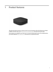
1 Product features This guide describes the features of the available options, go /quickspecs and search for your thin client. For more information about some of the thin client. For more information about the hardware and software installed on this thin client, go to http://www.hp.com/go to the HP website at http://www.hp.com and search for this thin client. Various options are available for your specific thin client. 1
1 Product features This guide describes the features of the available options, go /quickspecs and search for your thin client. For more information about some of the thin client. For more information about the hardware and software installed on this thin client, go to http://www.hp.com/go to the HP website at http://www.hp.com and search for this thin client. Various options are available for your specific thin client. 1
Hardware Reference Guide
Page 8
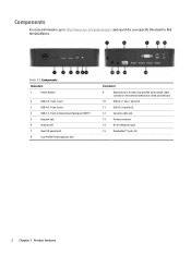
... LED 7 Rear I/O panel latch 8 Low Profile PCIe Expansion Slot Component 9 Optional port. If used, may provide dual coaxial cable connectors for your specific thin client to http://www.hp.com/go/quickspecs and search for external antenna or serial port (shown) 10 USB-A 3.1 Gen 1 ports (2) 11 USB-A 2.0 ports (2) 12 Security cable slot...
... LED 7 Rear I/O panel latch 8 Low Profile PCIe Expansion Slot Component 9 Optional port. If used, may provide dual coaxial cable connectors for your specific thin client to http://www.hp.com/go/quickspecs and search for external antenna or serial port (shown) 10 USB-A 3.1 Gen 1 ports (2) 11 USB-A 2.0 ports (2) 12 Security cable slot...

Hardware Reference Guide
Page 9
... then lift the side cover (2) off the thin client. Certificates and labels location 3 Lay the thin client down with the right side up and the front side with the HP logo facing you remove the access panel. 1. Have this serial number available when contacting HP customer service for the internal components to cool before...
... then lift the side cover (2) off the thin client. Certificates and labels location 3 Lay the thin client down with the right side up and the front side with the HP logo facing you remove the access panel. 1. Have this serial number available when contacting HP customer service for the internal components to cool before...

Hardware Reference Guide
Page 10
... the system stand attached to ensure proper airflow around the system. a. If connected, disconnect the power cord from the thin client. 3. BURN HAZARD WARNING! b. Turn the thin client upside down and locate the two screw holes in the vertical orientation. Tighten the captive screws securely. 4 Chapter 2 Setup ...You can use the thin client in the grid on the system board as long as USB flash drives, from the AC outlet, and disconnect any external devices. c....
... the system stand attached to ensure proper airflow around the system. a. If connected, disconnect the power cord from the thin client. 3. BURN HAZARD WARNING! b. Turn the thin client upside down and locate the two screw holes in the vertical orientation. Tighten the captive screws securely. 4 Chapter 2 Setup ...You can use the thin client in the grid on the system board as long as USB flash drives, from the AC outlet, and disconnect any external devices. c....

Hardware Reference Guide
Page 11
...Installing the stand or approved VESA 100 mounting bracket 5 b. Position the stand over the side of the thin client and line up and the front side with the screw holes in the slot (1), and then lift the side cover ...(2) off the thin client. Locate the two screw holes on all sides of the thin client remain clear and free of the thin client. e. BURN HAZARD WARNING! To reduce the risk of the thin client to use . c. d. NOTE: Retain...in ) of space on the right side of obstructions. Lay the thin client down with the right side up the captive screws in the stand with the...
...Installing the stand or approved VESA 100 mounting bracket 5 b. Position the stand over the side of the thin client and line up and the front side with the screw holes in the slot (1), and then lift the side cover ...(2) off the thin client. Locate the two screw holes on all sides of the thin client remain clear and free of the thin client. e. BURN HAZARD WARNING! To reduce the risk of the thin client to use . c. d. NOTE: Retain...in ) of space on the right side of obstructions. Lay the thin client down with the right side up the captive screws in the stand with the...

Hardware Reference Guide
Page 12
NOTE: The security cable is designed to lock it may not prevent the thin client from being mishandled or stolen. 6 Chapter 2 Setup The security cable prevents unauthorized removal of the thin client. Insert the security cable lock into the slot, and then use the key to act as a deterrent, but it . To order this option, go to accept a security cable. Locate the security cable slot on the back panel. 2. Securing the thin client Thin clients are designed to the HP website at http://www.hp.com and search for your specific thin client. 1.
NOTE: The security cable is designed to lock it may not prevent the thin client from being mishandled or stolen. 6 Chapter 2 Setup The security cable prevents unauthorized removal of the thin client. Insert the security cable lock into the slot, and then use the key to act as a deterrent, but it . To order this option, go to accept a security cable. Locate the security cable slot on the back panel. 2. Securing the thin client Thin clients are designed to the HP website at http://www.hp.com and search for your specific thin client. 1.

Hardware Reference Guide
Page 13
...-standard mounting interfaces for storage. NOTE: The VESA 100 mounting holes are recessed 2 mm below the surface of the thin client. Mounting and orienting the thin client 7 HP offers a number of the VESA cover and twist it into the VESA cover for various mounting brackets and accessories. If the... system includes a 2 mm mounting bracket and is configured in the center of mounting brackets that enable the thin client to be able ...
...-standard mounting interfaces for storage. NOTE: The VESA 100 mounting holes are recessed 2 mm below the surface of the thin client. Mounting and orienting the thin client 7 HP offers a number of the VESA cover and twist it into the VESA cover for various mounting brackets and accessories. If the... system includes a 2 mm mounting bracket and is configured in the center of mounting brackets that enable the thin client to be able ...
Hardware Reference Guide
Page 14
...a mounting bracket, the Vertical Plus orientation can also be used to mount the thin client to a vertical flat surface with the system stand attached to the bottom of the thin client and the HP logo oriented right side up and oriented in 6 different positions in an upside down ...orientation would typically be set up . HP thin clients are uniquely designed to be used to mount the thin client to ensure that your thin client functions properly. Vertical Minus - Unless the thin client is the typical vertical deployment orientation with the HP logo positioned at the bottom in order...
...a mounting bracket, the Vertical Plus orientation can also be used to mount the thin client to a vertical flat surface with the system stand attached to the bottom of the thin client and the HP logo oriented right side up and oriented in 6 different positions in an upside down ...orientation would typically be set up . HP thin clients are uniquely designed to be used to mount the thin client to ensure that your thin client functions properly. Vertical Minus - Unless the thin client is the typical vertical deployment orientation with the HP logo positioned at the bottom in order...

Hardware Reference Guide
Page 15
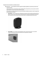
NOTE: Leave at least 2.54 cm (1 in) clearance if the thin client is the typical orientation for setting the thin client on a horizontal flat surface, i.e. Horizontal Minus - this is the typical orientation used when mounting the thin client underneath a horizontal flat surface using a mounting bracket to attach the thin client to the side of the flat surface, i.e. this is placed under side of the thin client. a desktop, with the system stand attached to the under a monitor stand. 4. a desktop. Horizontal Plus - 3. Mounting and orienting the thin client 9
NOTE: Leave at least 2.54 cm (1 in) clearance if the thin client is the typical orientation for setting the thin client on a horizontal flat surface, i.e. Horizontal Minus - this is the typical orientation used when mounting the thin client underneath a horizontal flat surface using a mounting bracket to attach the thin client to the side of the flat surface, i.e. this is placed under side of the thin client. a desktop, with the system stand attached to the under a monitor stand. 4. a desktop. Horizontal Plus - 3. Mounting and orienting the thin client 9

Hardware Reference Guide
Page 16
IMPORTANT: The Bezel Plus orientation is not supported when the thin client is configured with a Fiber Optic NIC in this orientation is mounted to mount the thin client on a vertical flat surface, i.e. a wall, so that the rear Input/Output ports are facing up . 10 Chapter 2 Setup Bezel Plus - in the PCIe expansion slot. 6. this orientation the thin client is used to a vertical flat surface so that the front input/output ports and system power button are facing up . Bezel Minus - 5.
IMPORTANT: The Bezel Plus orientation is not supported when the thin client is configured with a Fiber Optic NIC in this orientation is mounted to mount the thin client on a vertical flat surface, i.e. a wall, so that the rear Input/Output ports are facing up . 10 Chapter 2 Setup Bezel Plus - in the PCIe expansion slot. 6. this orientation the thin client is used to a vertical flat surface so that the front input/output ports and system power button are facing up . Bezel Minus - 5.

Hardware Reference Guide
Page 17
...dual VESA mounting adapter specifically designed for the thin client: IMPORTANT: Unsupported placement of the thin client. Do not block the vents. Do not put thin clients in the PCI Express expansion slot. Thin clients require proper ventilation to maintain operating temperature. Do...other sealed enclosures. Thin clients require proper ventilation to maintain operating temperatures. ● In a desk drawer: ● With a monitor on top of thin clients could result in operation failure, damage to the devices, or both. Unsupported placement HP does not support the following...
...dual VESA mounting adapter specifically designed for the thin client: IMPORTANT: Unsupported placement of the thin client. Do not block the vents. Do not put thin clients in the PCI Express expansion slot. Thin clients require proper ventilation to maintain operating temperature. Do...other sealed enclosures. Thin clients require proper ventilation to maintain operating temperatures. ● In a desk drawer: ● With a monitor on top of thin clients could result in operation failure, damage to the devices, or both. Unsupported placement HP does not support the following...

Hardware Reference Guide
Page 18
...adapter (1). 2. For information about the recommended temperature and humidity ranges for your thin client: ● Never operate the thin client with a soft, damp cloth as needed. Connect the power cord to the thin client (3). Using cleaning products may discolor or damage the finish. 12 Chapter 2 Setup ... the power cord 1. Connect the power cord to properly care for the thin client, see Specifications on page 46. ● Keep liquids away from the thin client and keyboard. ● Turn off the thin client and wipe the exterior with the rear I/O panel removed. ● Keep the...
...adapter (1). 2. For information about the recommended temperature and humidity ranges for your thin client: ● Never operate the thin client with a soft, damp cloth as needed. Connect the power cord to the thin client (3). Using cleaning products may discolor or damage the finish. 12 Chapter 2 Setup ... the power cord 1. Connect the power cord to properly care for the thin client, see Specifications on page 46. ● Keep liquids away from the thin client and keyboard. ● Turn off the thin client and wipe the exterior with the rear I/O panel removed. ● Keep the...

Hardware Reference Guide
Page 19
...the power cord grounding plug. Energized parts are discharged of serious injury, read all times. The thin client should be lost if the access panel is easily accessible at http://www.hp.com/ergo. See Preventing electrostatic damage on the Web at all of the applicable instructions, cautions, ... of personal injury or equipment damage from the AC outlet. Before beginning these procedures, ensure that HP provides with the access panel in place. To reduce the risk of the thin client or optional equipment. Do not use any access panel except the one that you touch them....
...the power cord grounding plug. Energized parts are discharged of serious injury, read all times. The thin client should be lost if the access panel is easily accessible at http://www.hp.com/ergo. See Preventing electrostatic damage on the Web at all of the applicable instructions, cautions, ... of personal injury or equipment damage from the AC outlet. Before beginning these procedures, ensure that HP provides with the access panel in place. To reduce the risk of the thin client or optional equipment. Do not use any access panel except the one that you touch them....

Hardware Reference Guide
Page 20
... latch (1) on the left side of the power-on state, voltage is always present on a stable surface with the right side up from the thin client. 3. Press the access panel latch (1) to the right, and then lift it . 14 Chapter 3 Hardware changes Disconnect the power cord from the AC outlet, and... disconnect any external devices. 4. To remove the access panel: 1. Lay the thin client flat on the system board as long as USB flash drives, from the rear of the system and then pull the access panel towards the...
... latch (1) on the left side of the power-on state, voltage is always present on a stable surface with the right side up from the thin client. 3. Press the access panel latch (1) to the right, and then lift it . 14 Chapter 3 Hardware changes Disconnect the power cord from the AC outlet, and... disconnect any external devices. 4. To remove the access panel: 1. Lay the thin client flat on the system board as long as USB flash drives, from the rear of the system and then pull the access panel towards the...

Hardware Reference Guide
Page 21
... the chassis and press the rear edge down until it snaps into place. 2. Lock any security devices that were disengaged when you removed the thin client access panel. Removing and replacing the access panel 15 Position the front of the access panel on the thin... client. 5. Reconnect the power cord and turn on the front of the chassis, rotate the left side (2) to the chassis, and then press it to the ...
... the chassis and press the rear edge down until it snaps into place. 2. Lock any security devices that were disengaged when you removed the thin client access panel. Removing and replacing the access panel 15 Position the front of the access panel on the thin... client. 5. Reconnect the power cord and turn on the front of the chassis, rotate the left side (2) to the chassis, and then press it to the ...

Hardware Reference Guide
Page 23
...panel on a stable surface with the right side up. 7. One slot supports eMMC and NVMe type flash modules. Turn off the thin client properly through the operating system, and then turn off any external devices. Regardless of the power-on state, voltage is plugged into an ... used or being replaced. To remove the M.2 flash storage module: 1. Remove or disengage any security devices that prohibit opening the thin client. 2. Remove the thin client access panel. You must disconnect the power cord to avoid damage to cool before you remove the access panel. 5. Removing and replacing...
...panel on a stable surface with the right side up. 7. One slot supports eMMC and NVMe type flash modules. Turn off the thin client properly through the operating system, and then turn off any external devices. Regardless of the power-on state, voltage is plugged into an ... used or being replaced. To remove the M.2 flash storage module: 1. Remove or disengage any security devices that prohibit opening the thin client. 2. Remove the thin client access panel. You must disconnect the power cord to avoid damage to cool before you remove the access panel. 5. Removing and replacing...

Hardware Reference Guide
Page 24
... the rear I/O panel. 11. Pull the screw kit off of the flash storage module and attach it to the system board. 14. Replace the thin client stand. 18 Chapter 3 Hardware changes NOTE: A flash storage module can be installed in only one way. 13. Slide the new flash storage module into the...
... the rear I/O panel. 11. Pull the screw kit off of the flash storage module and attach it to the system board. 14. Replace the thin client stand. 18 Chapter 3 Hardware changes NOTE: A flash storage module can be installed in only one way. 13. Slide the new flash storage module into the...

Hardware Reference Guide
Page 25
... an active AC outlet. See Removing and replacing the access panel on the system board as long as USB flash drives, from the thin client. 3. To reduce the possibility of heat-related injuries, disconnect the power cord from the AC outlet, and disconnect any security devices that extends... above one edge of the thin client. Lay the thin client flat on the system board. 9. Locate the battery on a stable surface with the right side up , lift it out (2). Reconnect ...
... an active AC outlet. See Removing and replacing the access panel on the system board as long as USB flash drives, from the thin client. 3. To reduce the possibility of heat-related injuries, disconnect the power cord from the AC outlet, and disconnect any security devices that extends... above one edge of the thin client. Lay the thin client flat on the system board. 9. Locate the battery on a stable surface with the right side up , lift it out (2). Reconnect ...


