
HP DTC Cabling and Racking Guide
Page 9
... US building codes. European computer racks all have options for 19" (482.6 mm) racks. When ordering a stand-alone computer rack, you plan to 240 V power distribution in North America and 230 V in the rack. The 240 V option is based on the common 20 amp limit of rack space. One EIA...). All racks are measured in the US for the 1.6 meter computer rack to the IEC and EIA standards for 120 V to install in Europe. 2 HP System Racks The HP System Racks conform to prevent current overloads. The 1.1 meter and 1.6 meter system racks are 905 mm deep with 2 filler panels.
... US building codes. European computer racks all have options for 19" (482.6 mm) racks. When ordering a stand-alone computer rack, you plan to 240 V power distribution in North America and 230 V in the rack. The 240 V option is based on the common 20 amp limit of rack space. One EIA...). All racks are measured in the US for the 1.6 meter computer rack to the IEC and EIA standards for 120 V to install in Europe. 2 HP System Racks The HP System Racks conform to prevent current overloads. The 1.1 meter and 1.6 meter system racks are 905 mm deep with 2 filler panels.

HP DTC Cabling and Racking Guide
Page 12
... any kind of gravity remains low, minimizing risk. Either standard or metric mounting hardware can be located in conjunction with the greatest power output towards the top of the system rack. DTC Racking Order DTC units should be used to the distribution panels, they are ... proper EIA unit increments. By racking the distribution panels at the bottom. When placed nearer the top, high power output components will install into the rack. System Rack Product Numbers HP 1.1 meter system rack - Rails sit in the system rack. C2785A 6 This promotes efficient cooling...
... any kind of gravity remains low, minimizing risk. Either standard or metric mounting hardware can be located in conjunction with the greatest power output towards the top of the system rack. DTC Racking Order DTC units should be used to the distribution panels, they are ... proper EIA unit increments. By racking the distribution panels at the bottom. When placed nearer the top, high power output components will install into the rack. System Rack Product Numbers HP 1.1 meter system rack - Rails sit in the system rack. C2785A 6 This promotes efficient cooling...

HP DTC Cabling and Racking Guide
Page 23
Push it in place. Put the power button from the accessories kit in at the top. 4 Racking a DTC 72MX with a desktop front panel 3 Screw the side brackets to the rack using four screws and washers supplied with your mounting kit. 4 The desktop panel is attached by slotting it into the lower edge of the DTC and pushing it onto the power switch through the DTC front panel. 17
Push it in place. Put the power button from the accessories kit in at the top. 4 Racking a DTC 72MX with a desktop front panel 3 Screw the side brackets to the rack using four screws and washers supplied with your mounting kit. 4 The desktop panel is attached by slotting it into the lower edge of the DTC and pushing it onto the power switch through the DTC front panel. 17

HP DTC Cabling and Racking Guide
Page 107
... be undertaken while there is a likelihood of an outdoor section of buildings, especially roofing. Prior to LAN cable installation, check that the building's power installation complies with the path of lightning conductors, and they should be insulated from the outside surfaces of the cable being struck by lightening. 101...
... be undertaken while there is a likelihood of an outdoor section of buildings, especially roofing. Prior to LAN cable installation, check that the building's power installation complies with the path of lightning conductors, and they should be insulated from the outside surfaces of the cable being struck by lightening. 101...

HP DTC Cabling and Racking Guide
Page 111
...DTC 72MX asynchronous processor boards 37 cable management 14 diagnostic port 39 example connections 36 front panels 13 maximum in rack 11 racking in non-HP racks 13 racking with desktop front panel 16 racking with system rack front panel 14 rail type 10 to 8-port DDP 41 to 8-... 69 L LAN supported cables 102 supported transceivers 102 M Modem Distribution Panel accessories 22 front mounting 22 racking 22 rear mounting 24 P patch panels 86 power button desktop front panel 17 protocol analyzer connection 66 R rail product numbers 7 rails types 7 RS-232 over twisted pair 84 standard 70 with 10BaseT...
...DTC 72MX asynchronous processor boards 37 cable management 14 diagnostic port 39 example connections 36 front panels 13 maximum in rack 11 racking in non-HP racks 13 racking with desktop front panel 16 racking with system rack front panel 14 rail type 10 to 8-port DDP 41 to 8-... 69 L LAN supported cables 102 supported transceivers 102 M Modem Distribution Panel accessories 22 front mounting 22 racking 22 rear mounting 24 P patch panels 86 power button desktop front panel 17 protocol analyzer connection 66 R rail product numbers 7 rails types 7 RS-232 over twisted pair 84 standard 70 with 10BaseT...
HP DTC Cabling and Racking Guide
Page 112
Index S standard cable lengths 75 system racks 1.1 meter 5 1.6 meter 4 DTC racking order 6 EIA units 3 guidelines for racking systems 6 HP 3 non-HP 13 populating 11 power supply 3 product numbers 6 rails 6 rear door 5 T twisted pair cables 84 typical configurations 29 V V.35 cable 98 X X.25 boards 97 106
Index S standard cable lengths 75 system racks 1.1 meter 5 1.6 meter 4 DTC racking order 6 EIA units 3 guidelines for racking systems 6 HP 3 non-HP 13 populating 11 power supply 3 product numbers 6 rails 6 rear door 5 T twisted pair cables 84 typical configurations 29 V V.35 cable 98 X X.25 boards 97 106

Internal Cabling Guide for HP Smart Array Controllers
Page 6
..., pull the tabs on the insulator/dividers to another PCI card is located in slot 8, remove that locks the card in PCI slot 8 for the HP Integrity rx8620 Server Installing the HP Smart Array 5302 or 5304 Controller Card Figure 1-2 Smart Array 5304 Controller Card Installing the... Array 5302 or 5304 Controller Card Step 1. The HP Smart Array 5302 or 5304 controller card must be installed in place by the bulkhead (see Figure 1-3). Once the card is running, shut down the OS, power off the server, and unplug the power cord. Step 2. If another slot. Do this by twisting the...
..., pull the tabs on the insulator/dividers to another PCI card is located in slot 8, remove that locks the card in PCI slot 8 for the HP Integrity rx8620 Server Installing the HP Smart Array 5302 or 5304 Controller Card Figure 1-2 Smart Array 5304 Controller Card Installing the... Array 5302 or 5304 Controller Card Step 1. The HP Smart Array 5302 or 5304 controller card must be installed in place by the bulkhead (see Figure 1-3). Once the card is running, shut down the OS, power off the server, and unplug the power cord. Step 2. If another slot. Do this by twisting the...

Internal Cabling Guide for HP Smart Array Controllers
Page 16
...card is ordered). Step 2. Step 3. Once the card is running, shut down the OS, power off the server, and unplug the power cord. Remove the top cover of the Smart Array 6402 or 6404 controller card. The HP Smart Array 6402 or 6404 controller card must be installed in place by twisting the... blue paddle that card and relocate it to unseat the card. Cabling for the HP Integrity rx7620 Server...
...card is ordered). Step 2. Step 3. Once the card is running, shut down the OS, power off the server, and unplug the power cord. Remove the top cover of the Smart Array 6402 or 6404 controller card. The HP Smart Array 6402 or 6404 controller card must be installed in place by twisting the... blue paddle that card and relocate it to unseat the card. Cabling for the HP Integrity rx7620 Server...

Internal Cabling Guide for HP Smart Array Controllers
Page 27
...Step 1. d. The HP Smart Array 5302 or 5304 controller card must be installed in place. Remove the corresponding PCI card. Slide the PCI card separator/extractor out of the server: a. c. Cabling for internal RAID. If the server is running, shut down the OS, power off the server, and... unplug the power cord. Press one on either side of the chassis (see Figure 3-3). Remove the side cover of the PCI card cage. ...
...Step 1. d. The HP Smart Array 5302 or 5304 controller card must be installed in place. Remove the corresponding PCI card. Slide the PCI card separator/extractor out of the server: a. c. Cabling for internal RAID. If the server is running, shut down the OS, power off the server, and... unplug the power cord. Press one on either side of the chassis (see Figure 3-3). Remove the side cover of the PCI card cage. ...
Internal Cabling Guide for HP Smart Array Controllers
Page 35
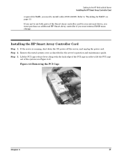
...along with the back edge of the PCI cage in the server's operation and maintenance guide. Installing the HP Smart Array Controller Card Step 1. Step 3. If you opt to use both ports of the system ... Cage Chapter 4 31 Refer to "Recabling for your internal drives, you must purchase an additional HP Smart Array controller if you need to lift the PCI cage out of the Smart Array controller ...cover as described in order to install cable A7231-63025. Cabling for the HP 9000 rp3440 Server Installing the HP Smart Array Controller Card required for RAID, you want external RAID mass storage...
...along with the back edge of the PCI cage in the server's operation and maintenance guide. Installing the HP Smart Array Controller Card Step 1. Step 3. If you opt to use both ports of the system ... Cage Chapter 4 31 Refer to "Recabling for your internal drives, you must purchase an additional HP Smart Array controller if you need to lift the PCI cage out of the Smart Array controller ...cover as described in order to install cable A7231-63025. Cabling for the HP 9000 rp3440 Server Installing the HP Smart Array Controller Card required for RAID, you want external RAID mass storage...
Internal Cabling Guide for HP Smart Array Controllers
Page 38
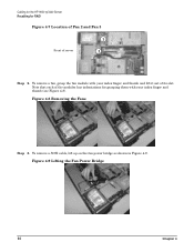
To remove a fan, grasp the fan module with your index finger and thumb and lift it out of server 3 2 Step 2. Figure 4-8 Removing the Fans Step 3. Cabling for the HP 9000 rp3440 Server Recabling for grasping them with your index finger and thumb (see Figure 4-8). Figure 4-9 Lifting the Fan Power Bridge 34 Chapter 4 To remove a SCSI cable, lift up on the fan power bridge as shown in Figure 4-9. Note that each of the modules has indentations for RAID Figure 4-7 Location of Fan 2 and Fan 3 Front of its slot.
To remove a fan, grasp the fan module with your index finger and thumb and lift it out of server 3 2 Step 2. Figure 4-8 Removing the Fans Step 3. Cabling for the HP 9000 rp3440 Server Recabling for grasping them with your index finger and thumb (see Figure 4-8). Figure 4-9 Lifting the Fan Power Bridge 34 Chapter 4 To remove a SCSI cable, lift up on the fan power bridge as shown in Figure 4-9. Note that each of the modules has indentations for RAID Figure 4-7 Location of Fan 2 and Fan 3 Front of its slot.
Internal Cabling Guide for HP Smart Array Controllers
Page 39
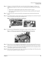
...card came in Figure 4-11. Step 9. Remove the two connector-screws for RAID Step 4. Chapter 4 35 Unplug one or both channels of the HP Smart Array controller card: • Single channel: unplug backplane SCSI cable Channel A (bottom) connector • Dual channel: unplug backplane SCSI cable Channel... A (bottom) and SCSI cable Channel B (top) connectors Step 5. Disconnect the power cables and any LAN or telecommunications cables from the back of the server chassis). Figure 4-10 Removing the Power Connectors Step 7. Remove the card by grasping it by the edges and pulling it against...
...card came in Figure 4-11. Step 9. Remove the two connector-screws for RAID Step 4. Chapter 4 35 Unplug one or both channels of the HP Smart Array controller card: • Single channel: unplug backplane SCSI cable Channel A (bottom) connector • Dual channel: unplug backplane SCSI cable Channel... A (bottom) and SCSI cable Channel B (top) connectors Step 5. Disconnect the power cables and any LAN or telecommunications cables from the back of the server chassis). Figure 4-10 Removing the Power Connectors Step 7. Remove the card by grasping it by the edges and pulling it against...
Internal Cabling Guide for HP Smart Array Controllers
Page 42
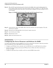
...to avoid crimping. Figure 4-17 RAID Cable Routing Through the PCI Cage Board Cover Step 15. Lower the fan power bridge. Step 19. Cabling for the HP 9000 rp3440 Server Configuring the Server Firmware and Software for an external RAID storage system 38 Chapter 4 Place the PCI...6402/6404 Controller Installation Guide: • Configure your RAID • Configure the HP Smart Array controller card for RAID Step 14. Step 17. Replace the metal system cover. Reinstall the iLO Manageability Card and power supply connectors. Step 16. The cable connectors are marked. Connect the free end...
...to avoid crimping. Figure 4-17 RAID Cable Routing Through the PCI Cage Board Cover Step 15. Lower the fan power bridge. Step 19. Cabling for the HP 9000 rp3440 Server Configuring the Server Firmware and Software for an external RAID storage system 38 Chapter 4 Place the PCI...6402/6404 Controller Installation Guide: • Configure your RAID • Configure the HP Smart Array controller card for RAID Step 14. Step 17. Replace the metal system cover. Reinstall the iLO Manageability Card and power supply connectors. Step 16. The cable connectors are marked. Connect the free end...

Internal Cabling Guide for HP Smart Array Controllers
Page 46
... PCI cage in order to lift the PCI cage out of the Smart Array controller card for your internal drives, you must purchase an additional HP Smart Array controller if you opt to install cable A7231-63025 as described in this chapter. If the server is running, shut down the OS..., power off the server, and unplug the power cord. Remove the metal system cover as described in the "Recabling for RAID" section later in the server's operation and maintenance guide...
... PCI cage in order to lift the PCI cage out of the Smart Array controller card for your internal drives, you must purchase an additional HP Smart Array controller if you opt to install cable A7231-63025 as described in this chapter. If the server is running, shut down the OS..., power off the server, and unplug the power cord. Remove the metal system cover as described in the "Recabling for RAID" section later in the server's operation and maintenance guide...

Internal Cabling Guide for HP Smart Array Controllers
Page 49
...whether you want to use one or both channels of the server. Chapter 5 45 See Figure 5-10. Disconnect the power cables and any LAN or telecommunications cables from the back of the HP Smart Array controller card: • Single channel: unplug backplane SCSI cable Channel A (bottom) connector • Dual...in Figure 5-11. Figure 5-10 Removing the Fans Step 3. Note that each of its slot. Figure 5-11 Lifting the Fan Power Bridge Step 4. Cabling for the HP Integrity rx2620 and rx2600 Servers Recabling for grasping them with your index finger and thumb. To remove a fan, grasp the fan ...
...whether you want to use one or both channels of the server. Chapter 5 45 See Figure 5-10. Disconnect the power cables and any LAN or telecommunications cables from the back of the HP Smart Array controller card: • Single channel: unplug backplane SCSI cable Channel A (bottom) connector • Dual...in Figure 5-11. Figure 5-10 Removing the Fans Step 3. Note that each of its slot. Figure 5-11 Lifting the Fan Power Bridge Step 4. Cabling for the HP Integrity rx2620 and rx2600 Servers Recabling for grasping them with your index finger and thumb. To remove a fan, grasp the fan ...

Internal Cabling Guide for HP Smart Array Controllers
Page 50
...RAID Step 6. Use a T-15 torx driver to the system board. Disconnect the iLO Manageability card connector (orange) as shown in . Cabling for the HP Integrity rx2620 and rx2600 Servers Recabling for the 25-Pin Management Port located on the right end of the card (holding the iLO Manageability Card...13. Step 9. Remove the card by grasping it by the edges and pulling it against the back of the system. Figure 5-12 Removing the Power Connectors Step 7. Figure 5-13Disconnecting the iLO Manageability Card Connector Step 8. Place the card on the far left and right sides of the card when ...
...RAID Step 6. Use a T-15 torx driver to the system board. Disconnect the iLO Manageability card connector (orange) as shown in . Cabling for the HP Integrity rx2620 and rx2600 Servers Recabling for the 25-Pin Management Port located on the right end of the card (holding the iLO Manageability Card...13. Step 9. Remove the card by grasping it by the edges and pulling it against the back of the system. Figure 5-12 Removing the Power Connectors Step 7. Figure 5-13Disconnecting the iLO Manageability Card Connector Step 8. Place the card on the far left and right sides of the card when ...

Internal Cabling Guide for HP Smart Array Controllers
Page 53
... controller card to the backplane. Step 17. Replace the metal system cover. Step 16. Lower the fan power bridge. Reinstall the iLO Manageability Card and power supply connectors. Step 20. Step 18. Cabling for the HP Integrity rx2620 and rx2600 Servers Configuring the Server Firmware and Software for your server's internal hot swap...
... controller card to the backplane. Step 17. Replace the metal system cover. Step 16. Lower the fan power bridge. Reinstall the iLO Manageability Card and power supply connectors. Step 20. Step 18. Cabling for the HP Integrity rx2620 and rx2600 Servers Configuring the Server Firmware and Software for your server's internal hot swap...

Internal Cabling Guide for HP Smart Array Controllers
Page 57
...PCI slot 2 (half-length slot). Figure 6-2 SCSI Channel A Connector on the cable release strap (see Figure 6-2). Chapter 6 53 Step 5. Install the HP Smart Array controller card in PCI slot 1 (full-length slot). Orient the PCI cage with the installed card component-side-up to allow routing of... installed in slot 1 (full-length slot) of the chassis fans. Then the SCSI cable is running, shut down the OS, power off the server, and unplug the power cord. Step 2. Step 3. Then reinstall the card after the SCSI cable has been disconnected. Step 1. Disconnect the SCSI cable from...
...PCI slot 2 (half-length slot). Figure 6-2 SCSI Channel A Connector on the cable release strap (see Figure 6-2). Chapter 6 53 Step 5. Install the HP Smart Array controller card in PCI slot 1 (full-length slot). Orient the PCI cage with the installed card component-side-up to allow routing of... installed in slot 1 (full-length slot) of the chassis fans. Then the SCSI cable is running, shut down the OS, power off the server, and unplug the power cord. Step 2. Step 3. Then reinstall the card after the SCSI cable has been disconnected. Step 1. Disconnect the SCSI cable from...

Internal Cabling Guide for HP Smart Array Controllers
Page 58
... heatsink Channel A1 Step 8. See Figure 6-4. See Figure 6-5. 54 Chapter 6 See Figure 6-3. Step 13. Figure 6-4 Cable Routing Under Power Supply Bracket Power Supply Bracket Step 14. Route the SCSI cable through the access slot of the PCI slot 2 connector. Step 9. Reinstall any accessory cards... rx1620 Server Installing the HP Smart Array 6402 Controller Card Figure 6-3 Cable Routing on Smart Array Card and PCI Cage Exit parallel to the connector on the controller card and under the power supply bracket. Step 11. Attach the SCSI Channel A connector (previously removed ...
... heatsink Channel A1 Step 8. See Figure 6-4. See Figure 6-5. 54 Chapter 6 See Figure 6-3. Step 13. Figure 6-4 Cable Routing Under Power Supply Bracket Power Supply Bracket Step 14. Route the SCSI cable through the access slot of the PCI slot 2 connector. Step 9. Reinstall any accessory cards... rx1620 Server Installing the HP Smart Array 6402 Controller Card Figure 6-3 Cable Routing on Smart Array Card and PCI Cage Exit parallel to the connector on the controller card and under the power supply bracket. Step 11. Attach the SCSI Channel A connector (previously removed ...

Internal Cabling Guide for HP Smart Array Controllers
Page 59
Cabling for closing up the server, installing it in the HP Integrity rx1600 Operation and Maintenance Guide for the HP Integrity rx1620 Server Installing the HP Smart Array 6402 Controller Card Figure 6-5 Cable Routing at SCSI Cage Do not block fans Route over IDE cable (if present) Step 15. Chapter 6 55 To enable RAID, refer to the controller card documentation. Complete the installation by following the instructions provided in a rack, and powering it up.
Cabling for closing up the server, installing it in the HP Integrity rx1600 Operation and Maintenance Guide for the HP Integrity rx1620 Server Installing the HP Smart Array 6402 Controller Card Figure 6-5 Cable Routing at SCSI Cage Do not block fans Route over IDE cable (if present) Step 15. Chapter 6 55 To enable RAID, refer to the controller card documentation. Complete the installation by following the instructions provided in a rack, and powering it up.
