
HP DTC Cabling and Racking Guide
Page 93
... a cabling conversion using 6 wires per port and provides 8 ports per 25 pair cables (or 50-pin telco-like connectors). CTS P0 - TXb/SGND P3 - RTS Jumpers ATT356A Pin # on RJ45 connector 5 4 1 2 3 6 5 4 1 2 3 6 5 4 1 2 3 6 5 4 1 2 3 6 5 87 RTS P2 - CTS P3 - RTS P1 - RXa/RD P1 - DTC Pin # on 50-pin connector 26 1 27 2 28 3 29...
... a cabling conversion using 6 wires per port and provides 8 ports per 25 pair cables (or 50-pin telco-like connectors). CTS P0 - TXb/SGND P3 - RTS Jumpers ATT356A Pin # on RJ45 connector 5 4 1 2 3 6 5 4 1 2 3 6 5 4 1 2 3 6 5 4 1 2 3 6 5 87 RTS P2 - CTS P3 - RTS P1 - RXa/RD P1 - DTC Pin # on 50-pin connector 26 1 27 2 28 3 29...

HP DTC Cabling and Racking Guide
Page 94
CTS P5 - TXa/TD P5 - RXa/RD P6 - TXb/SGND P7 - RXa/RD P7 - TXb/SGND Not Used Not Used Jumpers ATT356A Pin # on RJ45 connector 4 1 2 3 6 88 TXa/TD P4 - RXa/RD P5 - RTS P6 - TXa/TD P6 - TXb/SGND Not Used Not Used Pin # on ...
CTS P5 - TXa/TD P5 - RXa/RD P6 - TXb/SGND P7 - RXa/RD P7 - TXb/SGND Not Used Not Used Jumpers ATT356A Pin # on RJ45 connector 4 1 2 3 6 88 TXa/TD P4 - RXa/RD P5 - RTS P6 - TXa/TD P6 - TXb/SGND Not Used Not Used Pin # on ...

HP DTC Cabling and Racking Guide
Page 95
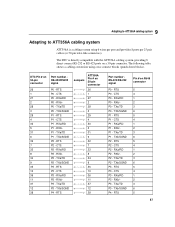
9 Adapting to ATT356A cabling system This conversion can also be achieved using RJ45 patch panels: DTC Pin # on RJ45 connector RS-423/RS-232 signal 6-wire ATT356A cable jumpers ATT356A Pin # on RJ45 connector RS-423/RS-232 signal Pair 1 RXa/RD 1 RXa/RD 2 2 RXb/- 2 RXb/- 2 3 TXa/TD 3 TXa/TD 3 4 RTS 4 RTS 1 5 CTS 5 CTS 1 6 TXb/SGND 6 TXb/SGND 3 7 Not Used 7 Not Used 4 8 Not Used 8 Not Used 4 89
9 Adapting to ATT356A cabling system This conversion can also be achieved using RJ45 patch panels: DTC Pin # on RJ45 connector RS-423/RS-232 signal 6-wire ATT356A cable jumpers ATT356A Pin # on RJ45 connector RS-423/RS-232 signal Pair 1 RXa/RD 1 RXa/RD 2 2 RXb/- 2 RXb/- 2 3 TXa/TD 3 TXa/TD 3 4 RTS 4 RTS 1 5 CTS 5 CTS 1 6 TXb/SGND 6 TXb/SGND 3 7 Not Used 7 Not Used 4 8 Not Used 8 Not Used 4 89

HP DTC Cabling and Racking Guide
Page 96
... per port and provides 12 ports on a 25 pair cable (or on a 50-pin connector. RXb/P0 - CTS P2 - RXb/P2 - CTS P3 - TXb/SGND Jumpers 10BaseT Pin # on 50-pin connector 26 1 27 2 28 3 29 4 30 5 31 6 32 7 33 8 Port number RS-423/RS-232 signal Pin # on 50-pin...
... per port and provides 12 ports on a 25 pair cable (or on a 50-pin connector. RXb/P0 - CTS P2 - RXb/P2 - CTS P3 - TXb/SGND Jumpers 10BaseT Pin # on 50-pin connector 26 1 27 2 28 3 29 4 30 5 31 6 32 7 33 8 Port number RS-423/RS-232 signal Pin # on 50-pin...

HP DTC Cabling and Racking Guide
Page 97
... - RTS P6 - CTS P7 - TXb/SGND 6 P5 - TXa/TD 3 P6 - RXb/- 2 P7 - RTS P4 - CTS P5 - TXa/TD P5 - TXb/SGND Not Used Not Used Jumpers 10BaseT Pin # on 50-pin connector 34 9 35 10 36 11 37 12 38 13 39 14 40 15 41 16 42 17 43 18...
... - RTS P6 - CTS P7 - TXb/SGND 6 P5 - TXa/TD 3 P6 - RXb/- 2 P7 - RTS P4 - CTS P5 - TXa/TD P5 - TXb/SGND Not Used Not Used Jumpers 10BaseT Pin # on 50-pin connector 34 9 35 10 36 11 37 12 38 13 39 14 40 15 41 16 42 17 43 18...

HP DTC Cabling and Racking Guide
Page 98
9 Adapting to a 10BaseT cabling system DTC Pin # on 50-pin connector Port number RS-423/RS232 signal Jumpers 10BaseT Pin # on RJ45 connector RS-423/RS-232 signal Pair 1 RXa/RD 1 RXa/RD 2 2 RXb/- 2 RXb/- 2 3 TXa/TD 3 TXa/TD 3 4 CTS 4 Not Used 1 5 RTS 5 ... # on RJ45 connector 3 6 1 2 3 6 1 2 3 6 1 2 This conversion can also be achieved using RJ45 patch panels: DTC Pin # on RJ45 connector RS-423/RS-232 signal 10BaseT cable jumpers (4 wires) 10BaseT Pin # on 50-pin connector 45 20 46 21 47 22 48 23 49 24 50 25 Port number RS-423/RS-232...
9 Adapting to a 10BaseT cabling system DTC Pin # on 50-pin connector Port number RS-423/RS232 signal Jumpers 10BaseT Pin # on RJ45 connector RS-423/RS-232 signal Pair 1 RXa/RD 1 RXa/RD 2 2 RXb/- 2 RXb/- 2 3 TXa/TD 3 TXa/TD 3 4 CTS 4 Not Used 1 5 RTS 5 ... # on RJ45 connector 3 6 1 2 3 6 1 2 3 6 1 2 This conversion can also be achieved using RJ45 patch panels: DTC Pin # on RJ45 connector RS-423/RS-232 signal 10BaseT cable jumpers (4 wires) 10BaseT Pin # on 50-pin connector 45 20 46 21 47 22 48 23 49 24 50 25 Port number RS-423/RS-232...

HP DTC Cabling and Racking Guide
Page 99
... - Not Used P0 - RXa/RD P1 - TXb/SGND P1 - CTS P2 - RTS P1 - RXa/RD P1 - RTS P2 - TXa/TD P2 - RXb/P3 - TXa/TD Jumpers ATT258A Pin # on 50-pin connector 26 1 27 2 28 3 29 4 30 5 31 6 32 7 33 8 34 9 35 10 36 11 37 Port number RS-423/RS232...
... - Not Used P0 - RXa/RD P1 - TXb/SGND P1 - CTS P2 - RTS P1 - RXa/RD P1 - RTS P2 - TXa/TD P2 - RXb/P3 - TXa/TD Jumpers ATT258A Pin # on 50-pin connector 26 1 27 2 28 3 29 4 30 5 31 6 32 7 33 8 34 9 35 10 36 11 37 Port number RS-423/RS232...

HP DTC Cabling and Racking Guide
Page 100
... P5 - CTS P5 - Not Used P5 - TXa/TD P4 - RTS P6 - RXb/P6 - TXb/SGND P7 - RXa/RD P7 - TXb/SGND Not Used Not Used Jumpers ATT258A Pin # on RJ45 connector 6 7 8 5 4 1 2 3 6 7 8 5 4 1 2 3 6 7 8 94 TXb/SGND P3 - RXa/RD P5 - RXb/P5 - RTS P7 - Not Used P4 - TXa/TD P5 - RXb/P4 - RTS...
... P5 - CTS P5 - Not Used P5 - TXa/TD P4 - RTS P6 - RXb/P6 - TXb/SGND P7 - RXa/RD P7 - TXb/SGND Not Used Not Used Jumpers ATT258A Pin # on RJ45 connector 6 7 8 5 4 1 2 3 6 7 8 5 4 1 2 3 6 7 8 94 TXb/SGND P3 - RXa/RD P5 - RXb/P5 - RTS P7 - Not Used P4 - TXa/TD P5 - RXb/P4 - RTS...

HP DTC Cabling and Racking Guide
Page 101
9 Adapting to an ATT258A cabling system This conversion can also be achieved using RJ45 patch panels: DTC Pin # on RJ45 connector RS-423/RS-232 signal ATT258A 8 wire cable jumper ATT258A Pin # on RJ45 connector RS-423/RS-232 signal Pair 1 RXa/RD 1 RXa/RD 2 2 RXb/- 2 RXb/- 2 3 TXa/TD 3 TXa/TD 3 4 CTS 4 CTS 1 5 RTS 5 RTS 1 6 TXb/SGND 6 TXb/SGND 3 7 Not Used 7 Not Used 4 8 Not Used 8 Not Used 4 95
9 Adapting to an ATT258A cabling system This conversion can also be achieved using RJ45 patch panels: DTC Pin # on RJ45 connector RS-423/RS-232 signal ATT258A 8 wire cable jumper ATT258A Pin # on RJ45 connector RS-423/RS-232 signal Pair 1 RXa/RD 1 RXa/RD 2 2 RXb/- 2 RXb/- 2 3 TXa/TD 3 TXa/TD 3 4 CTS 4 CTS 1 5 RTS 5 RTS 1 6 TXb/SGND 6 TXb/SGND 3 7 Not Used 7 Not Used 4 8 Not Used 8 Not Used 4 95

rp24xx A180 User Manual
Page 34
.... Repackaging the Cabinet for Shipment Use the original packing material to the PDU inside the cabinet. 3. Due to the weight of the UPS. 5. Remove the jumper cord from the SPU to repackage the cabinet for shipment. Check the condition of the convenience cords (output cord) that cord into one of the...
.... Repackaging the Cabinet for Shipment Use the original packing material to the PDU inside the cabinet. 3. Due to the weight of the UPS. 5. Remove the jumper cord from the SPU to repackage the cabinet for shipment. Check the condition of the convenience cords (output cord) that cord into one of the...

rp24xx A180 User Manual
Page 44
...disk drives when external devices are connected to the "SCSI (Single Ended) 8/16/5 path". 44 Chapter 2 NOTE The TERMINATION ENABLED jumper must be removed from your body to ground. Symptoms include failing to boot from operating properly. If an embedded disk is already installed...removed. NOTE Cabinet-mounted servers must be installed. Step 4. Failure to remove this address is recommended to be modified. Check configuration jumpers existing disks. Step 3. Place the disk carrier on all embedded disk drives. Remove the disk carrier by unscrewing the knurled captive ...
...disk drives when external devices are connected to the "SCSI (Single Ended) 8/16/5 path". 44 Chapter 2 NOTE The TERMINATION ENABLED jumper must be removed from your body to ground. Symptoms include failing to boot from operating properly. If an embedded disk is already installed...removed. NOTE Cabinet-mounted servers must be installed. Step 4. Failure to remove this address is recommended to be modified. Check configuration jumpers existing disks. Step 3. Place the disk carrier on all embedded disk drives. Remove the disk carrier by unscrewing the knurled captive ...

rp24xx A180 User Manual
Page 80
...Make sure that the disks are available via ODE and STM. NOTE Only licensed self-maintenance technicians and HP service personnel have unique addresses. Check disk configuration jumper settings. Use mapping utilities (Mapper) to verify that all the disks on top of the disk housing ...the A-Class Server Disk Drive Removal and Replacement section, or look at the firmware Main Menu prompt. Make sure the TERMINATION ENABLED jumper is applied to Initialize To troubleshoot a recurring embedded disk fault: 1. If you are unfamiliar with part number A5182-69101 or later....
...Make sure that the disks are available via ODE and STM. NOTE Only licensed self-maintenance technicians and HP service personnel have unique addresses. Check disk configuration jumper settings. Use mapping utilities (Mapper) to verify that all the disks on top of the disk housing ...the A-Class Server Disk Drive Removal and Replacement section, or look at the firmware Main Menu prompt. Make sure the TERMINATION ENABLED jumper is applied to Initialize To troubleshoot a recurring embedded disk fault: 1. If you are unfamiliar with part number A5182-69101 or later....
rp24xx A180 User Manual
Page 94
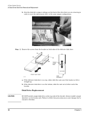
... the front of the bracket. Always install a single disk drive on top, either end of the defective disk drive. Note the disk drive jumper settings on the top rails of the drive that you are removing in order to reset the replacement drive to excessive vibration. 94 Chapter 3 ...Step 2. Failure to follow this precaution may cause damage due to the same jumper configuration. Remove the screws from the bracket on the bottom, slide the unit out of either slide the unit out of the bracket or lift...
... the front of the bracket. Always install a single disk drive on top, either end of the defective disk drive. Note the disk drive jumper settings on the top rails of the drive that you are removing in order to reset the replacement drive to excessive vibration. 94 Chapter 3 ...Step 2. Failure to follow this precaution may cause damage due to the same jumper configuration. Remove the screws from the bracket on the bottom, slide the unit out of either slide the unit out of the bracket or lift...
rp24xx A180 User Manual
Page 96
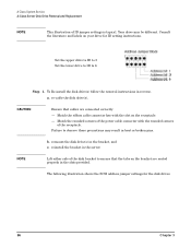
... follow the removal instructions in the slots provided. Match the rounded corners of the receptacle. The following illustration shows the SCSI address jumper settings for ID setting instructions. Failure to observe these precautions may be different. Set the upper drive to ID to 5 Set the...cable the disk drive(s), CAUTION Ensure that the tabs on your drive for the disk drives. 96 Chapter 3 NOTE Lift either side of ID jumper settings is typical. A-Class System Service A-Class Server Disk Drive Removal and Replacement NOTE This illustration of the disk bracket to 6 Step 1. ...
... follow the removal instructions in the slots provided. Match the rounded corners of the receptacle. The following illustration shows the SCSI address jumper settings for ID setting instructions. Failure to observe these precautions may be different. Set the upper drive to ID to 5 Set the...cable the disk drive(s), CAUTION Ensure that the tabs on your drive for the disk drives. 96 Chapter 3 NOTE Lift either side of ID jumper settings is typical. A-Class System Service A-Class Server Disk Drive Removal and Replacement NOTE This illustration of the disk bracket to 6 Step 1. ...